
Related Manuals for Webasto Scholastic Series


Summary of Contents for Webasto Scholastic Series
- Page 1 The Scholastic Series School Bus Heater Operating Instructions Installation Instructions For: Conventional Model Transit Model (Engine Front) Transit Model (Engine Rear)
-
Page 3: Table Of Contents
Operating your Webasto Scholastic Heater ........3-1... - Page 4 Heater Test Unit (Webasto P.N. 440280) ........
- Page 5 Wiring Diagram - Scholastic Series Heater ........
-
Page 6: Introduction
Webasto heating and cooling systems, and has been provided with the technical information, tools and General Safety Regulations and equipment required to properly complete the necessary Information installation /repairs. - Page 7 EBASTO CHOLASTIC ERIES NTRODUCTION In the vicinity of the coolant heater, a temperature of The coolant heater may only be operated with the 85 °C (185 °F) must not be exceeded under any specified fuel (Diesel 1, Diesel 2, Arctic grade, Kerosene circumstances (e.g.
-
Page 8: General Description
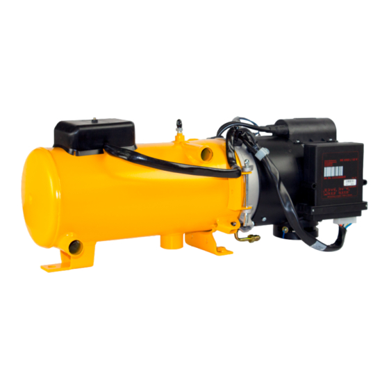
Inlet water pipe - 25 mm (1 in. OD.) 18 Combustion tube The Webasto Scholastic Series Heater has been designed for use on diesel powered school buses. Equipped with 1-inch coolant line connections, heavy-duty coolant pump, single fuel line and additional safety features makes this an ideal choice for school bus applications. -
Page 9: Functional Description
Upon pressing the “Instant Heat” button on the timer face, the “Operation Indicator” on the timer lights up and the heater begins operation. Using a Switch: When the switch is used for switching “ON” the Webasto heater, the “Operation Indicator” integrated in the switch is illuminated. Heater Start-up Sequence: The heater motor and coolant circulating pump begin operation. -
Page 10: Switching Off
Or switch the toggle switch or “Instant On” switch on your timer in the vehicle dash to “ON”. The heater will start up. 2. When the run time has elapsed on your timer or engine preheating is no longer required, switch the Webasto heater “OFF”. The heater will begin a brief after-run (cool down) cycle. - Page 11 EBASTO CHOLASTIC ERIES UNCTIONAL ESCRIPTION NOTE: We recommend that memory locations 1 and 2 be used for presetting starting times within a 24 hour period of setting the timer. Memory location 3 can be reserved for a starting time within the next 7 days of setting the timer. Location 3 is useful for occasional weekend or field trip operations outside of the normal schedule.
-
Page 12: 7-Day Digital Timer Programming And Operating Instructions
EBASTO CHOLASTIC ERIES UNCTIONAL ESCRIPTION 7-Day Digital Timer Programming and Operating Instructions Setting the time and Press the button for more than 2 seconds. day of the week Time display flashes. Press the button to set time of day. Wait 5 seconds. Time is now stored. Day of week flashes. -
Page 13: Technical Data
(inch) 254 (10) Dimensions of Heater Tray Mount 603 (23.75) 305 (12) mm (inch) 228 (9) Weight on Tray kg (lb.) 27 (60) Weight of Heater incl. Control Unit kg (lb.) 15 (33) Table 4-1: Scholastic Series Heater Data... -
Page 14: Scholastic Series Heater Dimensions
EBASTO CHOLASTIC ERIES ECHNICAL 4.1.1 Scholastic Series Heater Dimensions Fig. 4-1: Scholastic Series Heater Dimensions (Millimeters) -
Page 15: Coolant Circulation Pump Data
EBASTO CHOLASTIC ERIES ECHNICAL Coolant Circulation Pump Data Flow Rate l/hr (US gal/min) 3406 - 4542 (15 - 20) Rated Voltage 10 - 14 Power Consumption Dimensions 214 (8.42) 106 (4.16) mm (inch) 106 (4.16) Weight kg (lb.) 2.5 (5.5) Hose connection mm (inch) OD. -
Page 16: Tray Mount Dimensions
EBASTO CHOLASTIC ERIES ECHNICAL Tray Mount Dimensions Fig. 4-3: Tray Mount Dimensions (Inches) -
Page 17: Installation
NSTALLATION Installation General Information Webasto will take you step by step through the installation process to ensure successful operation for years to come. The installation must be performed in accordance with the installation instructions provided in this manual. NOTE: This manual does not cover all possible installations. This manual is a general guideline only. For special applications or installations differing from what is described in this manual, contact Webasto Thermosystems directly at 1-800-5 93-6000 for further information. -
Page 18: Mounting The Heater
EBASTO CHOLASTIC ERIES NSTALLATION Mounting the Heater Tray Kit mounting in existing enclosure on vehicle, i.e. battery box. 1. Ensure that the enclosure is large enough to accommodate the heater. Use the installation template provided with the heater kit. 2. The installation enclosure must provide adequate ventilation for combustion air requirements [20 cm² (4 in²)]. 3. -
Page 19: Combustion Air Supply
The Webasto heater is equipped with a high-performance circulating pump designed specifically for bus heating applications, and when plumbed in accordance with the following instructions, will maximize the heating systems efficiency. -
Page 20: Engine And Passenger Compartment Heating
A fuel fired Webasto heater equipped with a high capacity coolant pump can significantly increase the available heat supplied to a series plumbed system. -
Page 21: 5.6.3 Instructions For Integrating Into The Coolant System
This is the hose you will use to plumb the Webasto heater into the system. - Page 22 Remove hose clamping pliers and/ or open shut off valves. 9. Purge air from the Webasto heater by opening the bleeder valve screw (see page 2-1, figure 2-1, item 26). 10. Top off engine coolant as per engine manufacturer’s recommendations and re-install the radiator cap.
-
Page 23: Fuel System
EBASTO CHOLASTIC ERIES NSTALLATION Fuel System 5.7.1 General Description The fuel is drawn from the vehicles fuel tank through a fuel standpipe. This standpipe can be utilized on vehicles with a threaded port in the fuel tank for this purpose. IMPORTANT! Keep the fuel standpipe 50 mm (2”) from bottom of the fuel tank. -
Page 24: Fuel Line Parameters
EBASTO CHOLASTIC ERIES NSTALLATION 2. Install the universal fuel standpipe and 3/8” check valve. Check valve directional indication mark (arrow or symbol) must point in direction of fuel source (fuel tank). use 1/4” or 1/2” spare port on fuel tank and install fuel standpipe securely in fuel tank, use pipe thread sealant on all pipe threads. -
Page 25: Fuel Filter
MUST be filled with CLEAN diesel fuel. When replacing the fuel filter, this procedure must be repeated to ensure proper firing and operation. NOTE The Webasto Scholastic Series heater is equipped with an internal self-priming fuel pump. -
Page 26: Wiring Connections
Leave round waterproof harness to heater enclosure connector (P1) uncoupled until completion of heater installation. 1. Route and secure the wire harness from the Webasto heater to constant power source and cut harness to length. 2. Connect the positive leads to a 30 amp. circuit breaker connected to a constant power source. -
Page 27: Timer And Switch Connections
EBASTO CHOLASTIC ERIES NSTALLATION 5.8.3 Timer and Switch Connections For switch connection details (pin-outs) see wiring diagrams (fig.5-13, 5-14) on pages 5-13 and 5-14 appropriate to your installation. Fig. 5-10: On/Off Switch Pin-Out Connect To: Vehicle Dash Lights (Optional) Terminal 86 of Relay K1 Chassis Ground (Negative) To Control Unit Terminal Location B3 To Vehicle Ignition Signal (Positive) -
Page 28: Wiring Diagram - Scholastic Series Heater
EBASTO CHOLASTIC ERIES NSTALLATION 5.8.5 Wiring Diagram – Scholastic Series Heater Fig. 5-12: Wiring Diagram - Scholastic Series Heater 5-12... -
Page 29: Wiring Diagram - Chassis / Power Harness With Switch
EBASTO CHOLASTIC ERIES NSTALLATION 5.8.6 Wiring Diagram – Chassis / Power Harness with Switch 0030777A Option 1345-03 Fig. 5-13: Wiring Diagram - Chassis / Power Harness with Switch 5-13... -
Page 30: Wiring Diagram - Chassis / Power Harness With Switch
EBASTO CHOLASTIC ERIES NSTALLATION 5.8.7 Wiring Diagram – Chassis / Power Harness with Switch 0030522A Option 1345-03 Fig. 5-14: Wiring Diagram - Chassis / Power Harness with Switch 5-14... -
Page 31: Wiring Diagram - Chassis / Power Harness With Digital Timer Model 1531
EBASTO CHOLASTIC ERIES NSTALLATION 5.8.8 Wiring Diagram – Chassis / Power Harness with Digital Timer Model 1531 0030778 Option 1345-04 Fig. 5-15: Wiring Diagram - Chassis / Power Harness with Digital Timer Model 1531 5-15... -
Page 32: Wiring Diagram - Chassis / Power Harness With Digital Timer Model 1531
EBASTO CHOLASTIC ERIES NSTALLATION 5.8.9 Wiring Diagram – Chassis / Power Harness with Digital Timer Model 1531 0030512 Option 1345-04 Fig. 5-16: Wiring Diagram - Chassis / Power Harness with Digital Timer Model 1531 5-16... -
Page 33: Initial Operation
EBASTO CHOLASTIC ERIES NSTALLATION Initial Operation Before starting the heater for the first time, complete the following checklist: 5-17... - Page 34 EBASTO CHOLASTIC ERIES NSTALLATION Ω) Ensure battery is at ≥ 12.2Vdc for 12V, 24.4Vdc for 24V. 5-18...
- Page 35 EBASTO CHOLASTIC ERIES NSTALLATION 5-19...
-
Page 36: Annual Maintenance
Webasto trained and certified, skilled personnel. Ask your Webasto representative about training clinics. The Webasto heater requires a minimum of maintenance to operate. To keep your Webasto heater in good working order, the following maintenance procedures should be performed annually before each heating season: NOTE For major repairs and service parts, return to your authorized Webasto Thermosystems Specialist. -
Page 37: Basic Troubleshooting
Troubleshooting requires profound knowledge about structure and theory of operation of the heater. Troubleshooting may only be performed by Webasto trained and certified, skilled personnel. This section describes troubleshooting procedures for the Scholastic Series coolant heater. Troubleshooting is normally limited to the isolation of defective components. -
Page 38: Heater Test Unit (Webasto P.n. 440280)
ASIC ROUBLESHOOTING Heater Test Unit (Webasto P.N. 440280) The tester unit has been designed to quickly check the proper operation of the various heater components. By using the tester in place of the heater control unit, you are able to manually control the heater to test components and actually operate the unit in heating mode. -
Page 39: Test Procedures
* Inertia Switch: All 12 volt Scholastic Series heaters are equipped with a manual reset inertia switch usually located in the vicinity of the burner head (look for a device with a round diaphragm red in color and about the size of a 25 cent piece on top). - Page 40 EBASTO CHOLASTIC ERIES ASIC ROUBLESHOOTING 3. Manual test running of heater Turn the WATER PUMP switch “ON” Turn the MOTOR switch “ON” Push and hold the FUEL SOLENOID VALVE button “ON” (starts fuel flow to combustion chamber) Push and hold the IGNITION SPARK COIL button “ON”...
-
Page 41: Heater Lock Out Reset Procedure
IMPORTANT: Heater fault codes can be read using PC Diagnostics, however, the heater lockout reset must be manually performed using the procedure stated above. If you have any questions, contact our technical support team at (800) 860-7866 or via email at info-us@webasto.com. -
Page 42: Limited Non-Transferable Warranty
WARRANTY EBASTO CHOLASTIC ERIES Lim ited Non-Tr an sfe ra bl e W arran t y W eba sto The rm o & C om fo r t No r th Am e ri c a, Inc . (he re i n a fte r refe rre d to as Webas to) w ar r ants their heater s a nd he a ter ki t s ag a in s t d efe cts i n ma teri al and work m an s h ip for t wo (2 ) y ear s e ffecti ve a t the t im e o f i ns t al l ati o n o r ve hi cl e r egi s trati o n d a te for ori gi nal equip m en t i n s tall ati on ( OE M). - Page 43 N OT ES...
- Page 44 Webasto Thermo & Comfort N.A., Inc. 15083 North Road Fenton, MI 48430 Technical Assistance Hotline USA: (800) 555-4518 (800) 667-8900 Canada: www.webasto.us Org. 02/2001 Rev. 10/2018 P/N 50000058B www.techwebasto.com...
Need help?
Do you have a question about the Scholastic Series and is the answer not in the manual?
Questions and answers
Driving a bus with scholastic heater. It is not functioning. How would company go about having someone knowledgeable assess situation
A company can have a knowledgeable technician assess a non-functioning Webasto Scholastic Series heater by contacting an authorized Webasto dealer. The heater must be serviced by a certified or trained installer who has completed the factory training course for installation and repair. Warranty service and repairs should be administered through an authorized Webasto dealer in accordance with Webasto's warranty policy or contractual agreements.
This answer is automatically generated