
Related Manuals for Xylem NiCaVis 705 IQ


Summary of Contents for Xylem NiCaVis 705 IQ
- Page 1 OPERATING MANUAL ba75953e03 05/2017 NiCaVis 705 IQ OPTICAL SENSOR FOR NITRATE AND CARBON SUM PARAMETERS...
- Page 2 NiCaVis 705 IQ © Copyright 2017 Xylem Analytics Germany GmbH Printed in Germany. ba75953e03 05/2017...
-
Page 3: Table Of Contents
Measuring principle of the sensor NiCaVis 705 IQ ..6 Structure of the sensor NiCaVis 705 IQ ....7 Safety . - Page 4 NiCaVis 705 IQ Maintenance and cleaning ......37 Maintenance ........37 Sensor cleaning .
-
Page 5: Overview
Overview NiCaVis 705 IQ Overview How to use this component operating manual Structure of the IQ S IQ Sensor Net Operating Manual ENSOR operating manual System Operating Manual (Ring Binder) IQ Sensor MIQ Module MIQ Terminal Operating Operating Operating Manual... -
Page 6: Field Of Application
Overview NiCaVis 705 IQ Field of application The NiCaVis 705 IQ is an online sensor for the on-site determination of nitrate and carbon sum parameters in waste water treatment plants. The range of application comprises control, feedback control and monitoring. -
Page 7: Structure Of The Sensor Nicavis 705 Iq
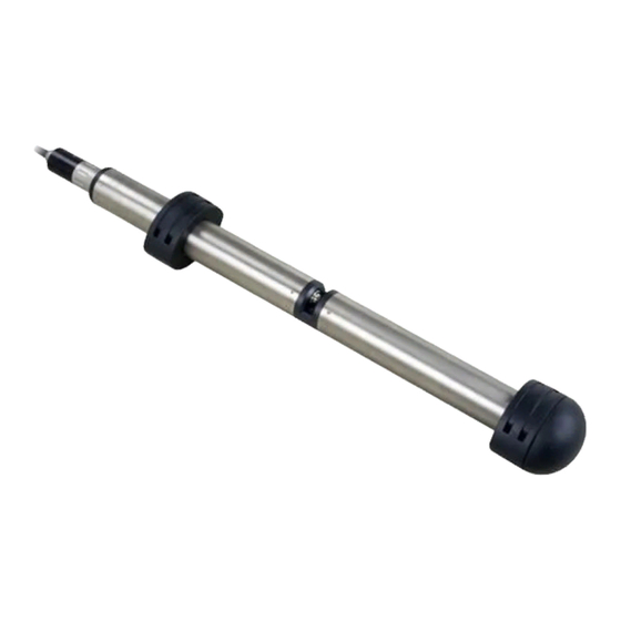
Overview NiCaVis 705 IQ Structure of the sensor NiCaVis 705 IQ The sensor has a light source (1), a measuring gap (3) to enable the contact of light with the measuring solution, and a detector (5) to measure the attenuated light beam. -
Page 8: Safety
Safety NiCaVis 705 IQ Safety Safety information 2.1.1 Safety information in the operating manual This operating manual provides important information on the safe operation of the product. Read this operating manual thoroughly and make yourself familiar with the product before putting it into operation or working with it. The operating manual must be kept in the vicinity of the sensor so you can always find the infor- mation you need. -
Page 9: Safe Operation
NiCaVis 705 IQ Safe operation 2.2.1 Authorized use The authorized use of the NiCaVis 705 IQ consists of its use as a sensor in the IQ S . Only the operation and running of the sensor according to the ENSOR... -
Page 10: Commissioning
Commissioning NiCaVis 705 IQ Commissioning IQ S system requirements ENSOR Software versions of The operation of the NiCaVis 705 IQ requires the following software versions in the controller and the IQ S ENSOR terminal components DIQ/S 28X Controller software: Version 3.72 or higher... -
Page 11: Installation
Do not suspend the sensor on the sensor connection cable. Risk of cable break and water penetration at the cable gland. A wide range of mounting accessories is available for the installation of the NiCaVis 705 IQ (see chapter 6 S PARE PARTS MAINTENANCE EQUIPMENT ACCES ). - Page 12 Commissioning NiCaVis 705 IQ Vertical installation For vertical installation, mount the sensor in a position that allows interfering ele- ments in the measuring gap to escape with the current. In the case of vertical installation, the minimum flow rate is 0.2 m/s so the measuring gap is kept clean optimally.
-
Page 13: Mounting The Shock Protectors
Commissioning NiCaVis 705 IQ 3.3.2 Mounting the shock protectors The shock protectors consist of two rings, a cap and four cable ties. To mount the shock protectors, proceed as follows: Sensor with mounted shock protectors Fig. 3-4 Mounting the shock protectors Plug the cap (pos. -
Page 14: Connecting The Sensor To The Iq Sensor Net
SACIQ, the SACIQ SW sensor connection cable is optimized regarding its corrosion resistance in seawater and brackish water and adapted for use in conjunction with the NiCaVis 705 IQ. Information on this and other IQ S accessories is given in the WTW catalog and on the Internet. - Page 15 Commissioning NiCaVis 705 IQ Connecting the Take the protective caps off the plug connections of the sensor and the sensor to the sensor SACIQ (SW) sensor connection cable and keep them safe. connection cable Plug the socket of the SACIQ (SW) sensor connection cable onto the plug head connector of the sensor.
-
Page 16: Initial Commissioning
Commissioning NiCaVis 705 IQ Initial commissioning 3.4.1 General information CAUTION Never look into the measuring window or put objects into the measuring window during operation! The emitted UV radiation can damage the eyes! In the case of authorized use, inadvertent eye contact with the light beam is not possible. -
Page 17: Sensor Structure
Main sensor The sensor for nitrate measurement is the main sensor. It registers on the system under the designation, NiCaVis 705 IQ and the series number of the physical sensor. Virtual sensors All other sensors for carbon measurement are virtual sensors. -
Page 18: Settings For The Main Sensor
Commissioning NiCaVis 705 IQ 3.4.3 Settings for the main sensor Measuring cycle A measuring cycle consists of the cleaning procedure, the adjustment time for the measuring system and the determination of the measured value. The follow- ing graphic demonstrates the relevant settings:... - Page 19 Commissioning NiCaVis 705 IQ Menu item Settings Explanations Measuring location Outlet Measurement location or application of (permanently set) the sensor. The possible measurement loca- tions are displayed depending on the currently set measuring mode. The sample matrix on which the cal-...
- Page 20 Commissioning NiCaVis 705 IQ Menu item Settings Explanations Response time t90 3 ... 60 min Response time of the signal smoothing. Depending on the sample matrix, mea- sured values can vary more or less strongly (e.g. due to foreign bodies or air bubbles).
-
Page 21: Settings For Virtual Sensors
Commissioning NiCaVis 705 IQ Menu item Settings Explanations Quit The display switches to the next higher level without storing the new settings. 3.4.4 Settings for virtual sensors Carrying out Using <S>, switch from the measured value display to the main menu of the settings settings. - Page 22 Commissioning NiCaVis 705 IQ Menu item Settings Explanations Main sensor Information that there are further sen- sor overlapping settings in the setting menu of the relevant main sensor Meas. interval Cleaning duration Air Signal smoothing etc.). Save and quit The system confirms the saving of the settings and the display switches to the next higher level.
-
Page 23: Measurement / Operation
Measurement / Operation NiCaVis 705 IQ Measurement / Operation Determination of measured values Physical sensor, series number xxx Absorbance spectrum Absorbance spectrum of zero adjustment of measurement Main Virtual sensor sensor software software Main sensor meas. mode Virtual sensor meas. mode... -
Page 24: Measurement Operation
Measurement / Operation NiCaVis 705 IQ Measurement operation CAUTION Never look into the measuring window or put objects into the measuring window during operation! The emitted UV radiation can damage the eyes! In the case of authorized use, inadvertent eye contact with the light beam is not possible. - Page 25 Measurement / Operation NiCaVis 705 IQ measured value at different points (see section 4.1): User calibration (see section 4.3.2) Zero adjustment Sensor check/ (see section 4.3.3). An overview diagram of the calibration procedures can be found on page 4 - 32.
- Page 26 Measurement / Operation NiCaVis 705 IQ Zero adjustment Sensor check (H2O dest.) While the just determines the current state of the Zero adjustment sensor, a can be used to compensate for changes of the Sensor check sensor. A zero adjustment can be required if, for example, the (H2O dest.)
-
Page 27: User Calibration
A value pair is determined at each point. Each value pair consists of the raw value of the NiCaVis 705 IQ sensor and the corresponding reference value. Each value pair has to be determined at the same time and place as the test sample as possible. - Page 28 The values must be in ascending order. If they are not in ascending order, a calibration error will occur. NiCaVis 705 IQ Switch off the maintenance condition (use <> Anzeige/ to select the sensor, press <OK> and make the setting in the Optionen menu).
- Page 29 Measurement / Operation NiCaVis 705 IQ The entry of calibration values outside the measuring range leads to a calibration error. Default values are marked in bold. Menu item Settings Explanations Cal - # raw value 1 CarboVis: Raw value of the first value pair -10000,00 ...
- Page 30 Measurement / Operation NiCaVis 705 IQ Information on the contents and structure of the log book and how you can call it up is given in the L chapter of the OG BOOK IQ S system operating manual. ENSOR The user calibration is not recorded in the calibration history. You...
-
Page 31: Sensor Check/Zero Adjustment
Measurement / Operation NiCaVis 705 IQ Zero adjustment 4.3.3 Sensor check/ NOTE The sensor check or Zero adjustment must be carried out under absolutely clean conditions. If you do not work carefully enough the Zero adjustment can deteriorate the measuring quality. - Page 32 Measurement / Operation NiCaVis 705 IQ Flowchart Cleaning the sensor Sensor check TEST: MEASUREMENT WINDOWS (H2O dist.) Clean the measurement windows Assessment number Rinse the measuring chamber -40 ... +40 < -40 or with ultrapure water several times > +40...
- Page 33 Prepare the sensor check or as follows: sensor check or Zero adjustment Switch to the measured value display with <M>. Use <> to select the NiCaVis 705 IQ sensor. Maintenance condition: Call up calibration with <C>. The Linked outputs are frozen. window appears.
- Page 34 Measurement / Operation NiCaVis 705 IQ Measuring chamber Sensor sleeve Fig. 4-4 Putting the sensor sleeve on the sensor Put the sensor in a horizontal position on a firm and vibration-free sur- face. Turn the filling opening of the sensor sleeve upward (Fig. 4-4).
- Page 35 Measurement / Operation NiCaVis 705 IQ Start measurement Confirm each checklist with <OK> until the display appears. Up to this point, you can break off the calibration procedure at any time with the <ESC> key. The system continues to work with the old calibration data.
- Page 36 Sensor check (standard) After the Thoroughly rinse the sensor and sensor sleeve with ultrapure water. NiCaVis 705 IQ Switch off the maintenance condition (use <> Display/ to select the sensor, press <OK> and make the setting in the Options menu).
-
Page 37: Maintenance And Cleaning
Maintenance and cleaning NiCaVis 705 IQ Maintenance and cleaning Maintenance The UV-VIS- NiCaVis 705 IQ sensor operates maintenance-free. Sensor cleaning 5.2.1 Cleaning agents and accessories Cleaning agents To clean the sensor, use the following cleaning agents only: Contamination Cleaning agents Water-soluble substances –... -
Page 38: General Steps To Be Taken
Maintenance and cleaning NiCaVis 705 IQ 5.2.2 General steps to be taken Depending on the application site and the level of contamination of the sensor as well as the coming job, the cleaning procedure includes the following parts: Every cleaning procedure starts with a basic cleaning. It removes tough grime such as incrustation of fouling matter, algae and biological deposits. -
Page 39: Basic Cleaning
Maintenance and cleaning NiCaVis 705 IQ 5.2.3 Basic cleaning Steps of the basic Take the sensor out of the test sample and remove any solid matter cleaning deposits and incrustation of fouling matter manually with a brush or sponge. Wash the sensor down with warm tapwater (30 - 50 °C). -
Page 40: Cleaning The Measuring Gap
Maintenance and cleaning NiCaVis 705 IQ 5.2.4 Cleaning the measuring gap To remove lime or grease deposits, use the flocked cleaning cards together with the following detergents: Contamination Cleaning agents Lime deposits Hydrochloric acid 5 % for analysis Grease deposits Mixture of isopropanol and water (approx. -
Page 41: Spare Parts, Maintenance Equipment, Accessories
Spare parts, maintenance equipment, accessories NiCaVis 705 IQ Spare parts, maintenance equipment, accessories General Description Model Order no. accessories, Calibration sleeve VIS/CV 481 074 replacement parts 20 flocked cleaning cards for cleaning the VIS/CT 481 071 measuring gap Cleaning set:... - Page 42 Spare parts, maintenance equipment, accessories NiCaVis 705 IQ Mounting Description Model Order no. accessories Mounting set for horizontal installation with VIS Set/EH 481 073 EH/F 170 swing mounting assembly Set for the mounting of UVVIS/SAC/NOx VIS Set/F 481 080 sensors to the S 200 electrode floater...
-
Page 43: What To Do If
What to do if... NiCaVis 705 IQ What to do if... "----" display Cause Remedy (invalid measured – User calibration values entered – Correct the entry and enter once value) incorrectly again (section 4.3.2) Sensor check (H2O dest.) – * –... - Page 44 What to do if... NiCaVis 705 IQ Drifting measured Cause Remedy values – Cleaning efficiency too low - mea- – Clean the measurement windows surement windows becoming (section 5.2.4) more and more contaminated – Use other cleaning method – Select different measurement loca- tion –...
- Page 45 – IQ S cable towards the – Install another power supply module ENSOR NiCaVis 705 IQ too long (voltage in the vicinity of the sensor drop too great) – Electrical connection between – Check the cable connection step-...
-
Page 46: Technical Data
Technical data NiCaVis 705 IQ Technical data Measurement characteristics Measuring principle Spectrophotometric Absorption measurement; integrated microprocessor elec- tronics, shielded 2-wire connection for power and data transmission. Light source Lamp type Xenon flashlamp Detector Photo diodes Wavelengths range 200 - 720 nm... -
Page 47: Application Characteristics
Technical data NiCaVis 705 IQ The quoted measuring ranges are nominal measuring ranges that are theoretically possible. In practice, real measuring ranges exist that are given by the limits of photometric determination. The limits are significantly influenced by the light scattering due to solids and the absorption of accompanying substances (sample matrix). -
Page 48: General Data
Technical data NiCaVis 705 IQ General data Dimensions hock protection: (in mm) Ø 96 Socket SACIQ... Ø 60 With shock protection: Ø 96 Weight Approx. 3.8 kg (without shock protectors and without sensor connec- tion cable) Approx. 4.8 kg (with shock protectors but without sensor connection... -
Page 49: Electrical Data
Technical data NiCaVis 705 IQ Meter safety Applicable norms – EN 61010-1 – UL 61010-1 – CAN/CSA C22.2#61010-1 – IEC 62471 Test certificates cETLus, CE Conforms to ANSI/UL 61010-1 Certified to CAN/CSA C22.2#61010-1" 2001759 Electrical data Nominal voltage Max. 24VDC... -
Page 50: Indexes
IQ S system for the ENSOR NiCaVis 705 IQ sensor. Information on the contents and structure of the log book and the structure of the message code is given in the L... -
Page 51: Error Messages
Indexes NiCaVis 705 IQ 9.1.1 Error messages Message code Message text Sensor temperature too high! EA2541 * Check process and application Sensor temperature too low! EA3541 * Check process and application Optical measuring range exceeded EAF541 * Check process (TSS or measured value too high) - Page 52 Indexes NiCaVis 705 IQ Message code Message text Overflow optical measurement ES4541 * Execute zero ajustment Failure optical measurement: hardware ES5541 * Contact service Failure optical measurement: software ES6541 * Contact service Failure optical measurement: software BIOS ES7541 * Contact service...
-
Page 53: Informative Messages
Indexes NiCaVis 705 IQ 9.1.2 Informative messages Message code Message text Calculation of negative concentrations IA23Ax * Perform user calibration or check user calibration Zero adjustment was successfully carried out IAC541 * Carry out sensor check * If required, carry out new user calibration Factory calibration has been activated. -
Page 54: Status Info
Indexes NiCaVis 705 IQ Status info The status info is a coded piece of information on the current status of a sensor. Each sensor sends this status info to the controller. The status info of sensors consists of 32 bits, each of which can have the value 0 or 1. -
Page 55: Appendix: Glossary
(see adjusting). Calibration value pair Value pair consisting of the raw value measured by the NiCaVis 705 IQ sensor, and a reference value measured e.g. by a laboratory determination. The calibration value pairs are the result of the user calibration. - Page 56 Appendix: Glossary NiCaVis 705 IQ Measuring gap The measuring gap is between the two measurement windows. In the measuring gap, the light beam penetrates the test sample. Measuring system The measuring system comprises all the devices used for measuring, e. g. measuring instrument and sensor. In addition, there is the cable and possibly an amplifier, terminal box and armature.
- Page 58 For more information on how Xylem can help you, go to xyleminc.com. ® Service address: Xylem Analytics Germany Sales GmbH &...
Need help?
Do you have a question about the NiCaVis 705 IQ and is the answer not in the manual?
Questions and answers