Table of Contents
Advertisement
Quick Links
Advertisement
Table of Contents

Related Manuals for Global American 3301500


Summary of Contents for Global American 3301500
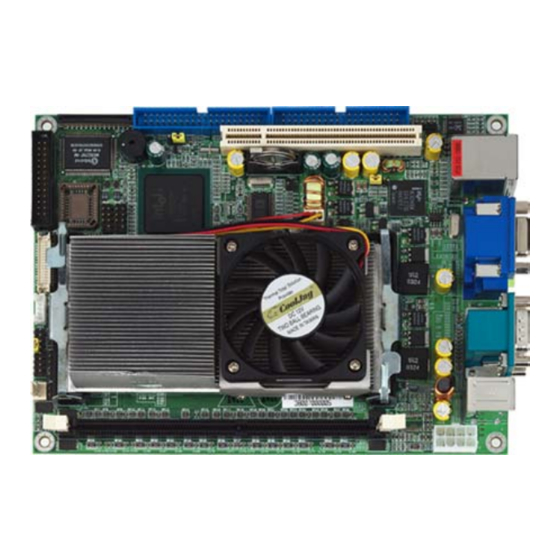
- Page 1 3301500 User’s Manual 5.25" Embedded Controller with Socket 479 Version 1.0...
- Page 2 Copyrights This document is copyrighted and all rights are reserved. It does not allow any non authorization in copied, photocopied, translated or reproduced to any electronic or machine readable form in whole or in part without prior written consent from the manufacturer.
-
Page 3: Table Of Contents
Table of Contents Chapter 1 Gerneral Description…………………….1 Major Features ..............2 Specifications ...............2 Board Dimensions............4 Chapter 2 Unpacking………………………………..5 Opening the Delivery Package ........5 Inspection..............5 Chapter 3 Hardware Installation…………………...7 Before Installation ............7 Board Layout ..............8 Jumper List ..............9 Connector List ..............9 Configuring the CPU ..........10 System Memory ............10 VGA Controller............10 PCI E-IDE Drive Connector ........ -
Page 5: Safety Instructions
Fasten the ALLIGATOR clip of the strap to the end of the shielded wire lead from a grounded object. Please wear and connect the strap before handling the 3301500 to protect yourself from the discharge of any static electricity through the strap. -
Page 7: General Description
I/O with CRT/LVDS Panel, Giga LAN, audio and USB2.0 ports interface. Its onboard ATA/33/66/100 to IDE drive interface architecture allows the 3301500 to support data transfers of 33, 66 or 100MB/sec. to each ® IDE drive connection. Designed with the Intel 82855GME/ICH4 core ®... -
Page 8: Major Features
Major Features The 3301500 comes with the following features: ® ® PGA 479 for Intel Pentium M 1.2~1.7GHz Supports 400MHz FSB One DDR socket with a max. capacity of 1GB ® Intel 82855GME/ICH4 system chipset Winbond W83627HF super I/O chipset... - Page 9 Parallel: One enhanced bi-directional parallel port supporting SPP/ECP/EPP Serial Port: 16C550 UART-compatible RS-232 x 2 serial ports with 16-byte FIFO IrDA: One TX/RX IrDA header USB: Supports six USB2.0 connectors Keyboard/Mouse: PS/2 6-pin Mini DIN BIOS: Award PnP Flash BIOS Watchdog Timer: Software program time-out intervals from 1~256 sec.
-
Page 10: Board Dimensions
Board Dimensions... -
Page 11: Unpacking
Chapter 2 Unpacking Opening the Delivery Package The 3301500 is packed in an anti-static bag. The board has components that are easily damaged by static electricity. Do not remove the anti-static wrapping until proper precautions have been taken. Safety Instructions in front of this manual describe anti-static precautions and procedures. - Page 12 It is recommended that you keep all the parts of the delivery package intact and store them in a safe/dry place for any unforeseen event requiring the returned shipment of the product. In case you discover anything missing and/or damaged items from the list of items, please contact your dealer immediately.
-
Page 13: Hardware Installation
Chapter 3 Hardware Installation This chapter provides the information on how to install the hardware using the 3301500. This chapter also contains information related to jumper settings of switch, watchdog timer selection, etc. Before Installation After confirming your package contents, you are now ready to install your hardware. -
Page 14: Board Layout
Board Layout... -
Page 15: Jumper List
Jumper List Jumper Default Setting Setting Page Clear CMOS Select: Normal Operation Short 1-2 Watchdog Timer Select: Reset Short 2-3 Bus Clock Rate Select: 400MHz FSB Short 1-2 Fan1 Voltage Select: +12V Short 1-2 Fan1 Voltage Select: +12V Short 1-2 Connector List Connector Definition... -
Page 16: Configuring The Cpu
Configuring the CPU The 3301500 offers the convenience in CPU installation with its auto-detect feature. After installing a new microprocessor onboard, the 3301500 automatically identifies the frequency and clock speed of the installed microprocessor chip, thereby eliminating the need for user to do additional CPU configuration or hardware settings related to it. -
Page 17: Pci E-Ide Drive Connector
PCI E-IDE Drive Connector CN3 and CN2 are standard 40-pin and 44-pin daisy-chain driver connectors that serve the PCI E-IDE drive provisions onboard the 3301500. A maximum of four ATA/33/66/100 IDE drives can be connected to the 3301500 via CN3 and CN2. - Page 18 CN3: Primary IDE Connector Description Description Reset IDE Host Data 7 Host Data 8 Host Data 6 Host Data 9 Host Data 5 Host Data 10 Host Data 4 Host Data 11 Host Data 3 Host Data 12 Host Data 2 Host Data 13 Host Data 1 Host Data 14...
- Page 19 CN2: Secondary IDE Connector Description Description Reset IDE Host Data 7 Host Data 8 Host Data 6 Host Data 9 Host Data 5 Host Data 10 Host Data 4 Host Data 11 Host Data 3 Host Data 12 Host Data 2 Host Data 13 Host Data 1 Host Data 14...
-
Page 20: Floppy Disk Drive Connector
Floppy Disk Drive Connector The 3301500 uses a slim 26-pin header connector, CN1, for floppy disk drive connection. A total of one FDD drive may be connected to CN1 at any given time. CN1: Slim FDD Connector Description Description Step... -
Page 21: Serial Port Connectors
3.10 Serial Port Connectors The 3301500 offers one NS16C550 compatible UART with Read/Receive 16-byte FIFO serial ports and two DB9 connectors. CN14: COM1/COM2 Connectors (DB9) PIN Description PIN Descriptio 3.11 Parallel Connector CN7 is a standard 26-pin flat cable connector designed to accommodate parallel port connection onboard the 3301500. -
Page 22: Ethernet Connector
Receive Input (-) Receive Input (+) FLD1+ FLD0+ FLD1- 3.13 USB Connector The 3301500 provides six USB ports at locations CN6, CN9 and CN8 for six USB connections to the 3301500. CN6: USB 0/1 Connector PIN Description PIN Description USB0- USB1-... -
Page 23: Cmos Data Clear
USB4- USB5- USB4+ USB5+ USB4+ USB5+ ---- ---- 3.14 CMOS Data Clear The 3301500 has a Clear CMOS jumper on JP1. JP1: Clear CMOS Options Settings Normal Operation Short 1-2 (default) Clear CMOS Short 2-3 Before you turn on the power of your system, please IMPORTANT: set JP1 to short 1-2 for normal operation. -
Page 24: Keyboard/Mouse Connectors
MS_Data MS_CLK 3.17 System Front Panel Connectors The 3301500 has one LED at location CN15(9-11) that indicates the HDD status. CN15(13-15) is the Reset Button connector onboard. CN15(1-3-5-7) is speaker, CN15(2-4-6) is power LED, CN15(8-10-12) is keylock, and CN15(14-16) is power switch. -
Page 25: Audio Connectors
3.18 Audio Connectors The 3301500 has an onboard AC97 3D audio interface. The following table list the pin assignments of the CD In and Audio connector. CN11: Audio Connector Description MIC In Blue Line In Green Line Out CN4: CD In Connector PIN Description PIN Description 3.19 IrDA Connector... - Page 26 The following sample programs show how to Enable, Disable and Refresh the Watchdog Timer: ;---------------------------------------------------------------------------------- ; Enter the WDT function mode, interruptible double-write ;---------------------------------------------------------------------------------- DX, 2EH AL, 87H DX, AL DX, AL DX, 2EH AL, 07H DX, AL DX, 2FH AL, 08H DX, AL DX, 2EH...
- Page 27 We will do our best to support your products, projects and business. Address: Global American, Inc. 17 Hampshire Drive Hudson, NH 03051 Telephone: Toll Free U.S. Only (800) 833-8999 (603) 886-3900 FAX: (603) 886-4545 Website: http://www.globalamericaninc.com Support: Technical Support at Global American...
Need help?
Do you have a question about the 3301500 and is the answer not in the manual?
Questions and answers