Table of Contents

Subscribe to Our Youtube Channel
Related Manuals for Tektronix Geoprobe G10


Summary of Contents for Tektronix Geoprobe G10
- Page 1 G10 Installation Guide Software Version 7.13.2 Supports ® GeoProbe IIC200/IAP320 IIC200/IAP200 IIC200/IAP100 IIC100/IAP200 IIC100/IAP100 Tektronix Communications | For Licensed Users | Unauthorized Duplication and Distribution Prohibited...
- Page 2 Copyright © Tektronix Communications, Inc. All rights reserved. Printed in the USA. Tektronix products are covered by U.S. and foreign patents, issued and pending. Information in this publication supersedes that in all previously published material. Specification and price change privileges reserved. TEKTRONIX and TEK are registered trademarks of Tektronix, Inc. The GeoProbe system uses the SmartHeap product for memory management.
-
Page 3: What's New In G10 Probe 7.13.2
The IIC100/IAP320 is not a recommended configuration and is not officially supported for qualified performance ratings. Tektronix Communications recommends upgrading systems to IIC200 when upgrading to the IAP320. G10 Installation Guide 7.13.2 Tektronix Communications | For Licensed Users | Unauthorized Duplication and Distribution Prohibited... -
Page 4: Table Of Contents
G10 Probe Power Cabling..................38 AC Units ......................38 DC Units ......................39 Storage Enclosure Power Cabling ................ 40 AC Units ......................40 G10 Installation Guide 7.13.2 Tektronix Communications | For Licensed Users | Unauthorized Duplication and Distribution Prohibited... - Page 5 1G Ethernet Cabling for Optical Taps/Splitters (IIC100) ........83 1G Ethernet Cabling for Mirror/Span Ports............85 10 Gigabit Ethernet Connections (TRM100 RTM) ..........86 10G Ethernet Cabling for Optical Taps/Splitters ..........87 G10 Installation Guide 7.13.2 Tektronix Communications | For Licensed Users | Unauthorized Duplication and Distribution Prohibited...
- Page 6 Replacing G10 Chassis Air Filters................118 Replacing the Top Air Filter ................118 Replacing the Bottom Air Filter ..............120 G10 Blade Removal/Replacement Procedures............123 IAP100 ......................123 G10 Installation Guide 7.13.2 Tektronix Communications | For Licensed Users | Unauthorized Duplication and Distribution Prohibited...
- Page 7 Appendix D G10 NEBS Requirements ....................164 Overview ........................164 G10 Probe Signal Port Requirements ................164 Storage Enclosure Bonding and Grounding Requirements ........165 Equipment Cooling Requirements................168 G10 Installation Guide 7.13.2 Tektronix Communications | For Licensed Users | Unauthorized Duplication and Distribution Prohibited...
-
Page 8: G10 New Installation And Upgrade Workflows
The installer will be stripping wires, attaching lugs, and wiring several components together. Wiring the components incorrectly can result in damage to the G10 and other components. G10 Installation Guide 7.13.2 Tektronix Communications | For Licensed Users | Unauthorized Duplication and Distribution Prohibited... -
Page 9: Chapter 1 G10 New Installation And Upgrade Workflows
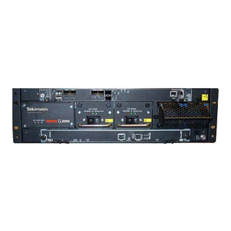
Figure 1.1 - G10 Probe Front Figure 1.2 shows the rear view of the G10 probe components for the IIC200 configuration. Figure 1.2 - G10 Probe Rear G10 Installation Guide 7.13.2 Tektronix Communications | For Licensed Users | Unauthorized Duplication and Distribution Prohibited... -
Page 10: G10 New Installation Workflow
Upgrade IIC Blade Page 12 Connect Ethernet and SAS Cabling Page 47 Connect G10 to the Monitored Network Page 76 Configure Probe Setup Page 15 G10 Installation Guide 7.13.2 Tektronix Communications | For Licensed Users | Unauthorized Duplication and Distribution Prohibited... -
Page 11: Upgrade Iris Server And Probe Software
Tektronix Communications recommends upgrading systems to IIC200 when upgrading to the IAP320. Step Action Shut down the probe (halt the system). G10 Installation Guide 7.13.2 Tektronix Communications | For Licensed Users | Unauthorized Duplication and Distribution Prohibited... -
Page 12: Upgrade Iic Blade
Perform the following steps to upgrade a probe from the IIC100 to the IIC200. The IIC200 supports two RTMs: SRM200 RTM (default configuration) TRM100 RTM (eHRPD monitoring only) G10 Installation Guide 7.13.2 Tektronix Communications | For Licensed Users | Unauthorized Duplication and Distribution Prohibited... - Page 13 - Remove only the 10G monitored network cabling. This cabling will be reconnected to the IIC200 on the front of the probe. G10 Installation Guide 7.13.2 Tektronix Communications | For Licensed Users | Unauthorized Duplication and Distribution Prohibited...
- Page 14 Monitored Link Cabling (IIC200) for details. Continue with Configure Probe Setup. Refer to Chapter 3 if necessary for troubleshooting Ethernet and SAS Cabling issues. G10 Installation Guide 7.13.2 Tektronix Communications | For Licensed Users | Unauthorized Duplication and Distribution Prohibited...
-
Page 15: Configure Probe Setup
Remove cabling from the IAP blade and RTM and remove them from the chassis. Reinsert the previously used RTM first, and then reinsert the IAP blade. G10 Installation Guide 7.13.2 Tektronix Communications | For Licensed Users | Unauthorized Duplication and Distribution Prohibited... -
Page 16: Iic100 Rollback Option
Reconfigure the disk array by reapplying the same profile to the probe; ALL call records stored on the probe will be lost. Verify that all G10 applications are running. Verify traffic on ISA and IPA. G10 Installation Guide 7.13.2 Tektronix Communications | For Licensed Users | Unauthorized Duplication and Distribution Prohibited... -
Page 17: Install Hardware And Power Cabling
(The fuse panel input terminals accept up to #2 AWG two-hole lug connectors on 1/4” screw terminals with 5/8” spacing—torque to 62 in-lbs) G10 Installation Guide 7.13.2 Tektronix Communications | For Licensed Users | Unauthorized Duplication and Distribution Prohibited... -
Page 18: G10 Hardware Installation Workflow
A Fuse Panel is only required for DC power configurations. Refer to Appendix C for procedures for removing and replacing G10 hardware components such as the blades and RTMs. G10 Installation Guide 7.13.2 Tektronix Communications | For Licensed Users | Unauthorized Duplication and Distribution Prohibited... -
Page 19: Install G10 Chassis
30-inch rack (see Figure 2.1) 36-inch rack (see Figure 2.2) 1000 mm rack (see Figure 2.2) 42-inch rack (see Figure 2.3) G10 Installation Guide 7.13.2 Tektronix Communications | For Licensed Users | Unauthorized Duplication and Distribution Prohibited... - Page 20 Attach bracket to side of chassis with four phillip flat-head screws at 1000mm/36” line Figure 2.2 - G10 Chassis Install, Four-Post Rack, Front Mount (36-inch and 1000 mm Racks) Tektronix Communications | For Licensed Users | Unauthorized Duplication and Distribution Prohibited...
- Page 21 Phillips flat-head screws at 42” line Align 42” line on bracket with rear of chassis Figure 2.3 - G10 Chassis Install, Four-Post Rack, Front Mount (42-inch Rack) Tektronix Communications | For Licensed Users | Unauthorized Duplication and Distribution Prohibited...
- Page 22 (30”, 36”, 42” or 1000 mm). Two or four screws are used depending on the rack. Continue with Install Storage Enclosures. G10 Installation Guide 7.13.2 Tektronix Communications | For Licensed Users | Unauthorized Duplication and Distribution Prohibited...
- Page 23 Step 5 Secure front of chassis to rack with four rackmount screws (30-inch rack install shown) Figure 2.5 - G10 Chassis Install, Four-Post Rack, Front Mount (30-inch Rack Shown) Tektronix Communications | For Licensed Users | Unauthorized Duplication and Distribution Prohibited...
-
Page 24: Two-Post Rack, Mid Mount
Install the front brackets to the sides of the G10 chassis using two Phillips flat head screws (Figure 2.6). Front Bracket Chassis Front Bracket Screws Figure 2.6 - G10 Chassis - Side View with Front Bracket G10 Installation Guide 7.13.2 Tektronix Communications | For Licensed Users | Unauthorized Duplication and Distribution Prohibited... - Page 25 (Figure 2.7). Secure the rear bracket to the back of the rack with two rackmount screws. Continue with Install Storage Enclosures. G10 Installation Guide 7.13.2 Tektronix Communications | For Licensed Users | Unauthorized Duplication and Distribution Prohibited...
-
Page 26: Install Storage Enclosures
Right Ear Cap Left Ear Cap Figure 2.8 - SA100R, SA100J, SA200R, and SA200J Storage Enclosure Ear Caps G10 Installation Guide 7.13.2 Tektronix Communications | For Licensed Users | Unauthorized Duplication and Distribution Prohibited... - Page 27 30-inch rack (does not use the side bracket) 36-inch rack (see Figure 2.10) 1000 MM rack (see Figure 2.11) 42-inch rack (see Figure 2.12) G10 Installation Guide 7.13.2 Tektronix Communications | For Licensed Users | Unauthorized Duplication and Distribution Prohibited...
- Page 28 Phillips flat-head screws at 36” lines Align 1000 MM line on bracket with rear of enclosure Figure 2.11 - Storage Enclosure Install, Four-Post Rack, Front Mount (1000 MM Rack) Tektronix Communications | For Licensed Users | Unauthorized Duplication and Distribution Prohibited...
- Page 29 Attach brackets to sides of enclosure with six Phillips flat-head screws at 42” lines Align 42” line on bracket with rear of enclosure Figure 2.12 - Storage Enclosure Install, Four-Post Rack, Front Mount (42-inch Rack) Tektronix Communications | For Licensed Users | Unauthorized Duplication and Distribution Prohibited...
- Page 30 Two or four screws are used depending on the rack depth. For DC configurations, continue with Install Fuse Panel. For AC configurations, continue with Connect Power Cabling. G10 Installation Guide 7.13.2 Tektronix Communications | For Licensed Users | Unauthorized Duplication and Distribution Prohibited...
- Page 31 Phillips pan-head screws and washers at holes appropriate for your rack depth (36-inch rack shown) Figure 2.14 - Storage Enclosure Install, Four-Post Rack, Front Mount (36-inch Rack Shown) Tektronix Communications | For Licensed Users | Unauthorized Duplication and Distribution Prohibited...
-
Page 32: Two-Post Rack, Mid Mount
3” to 4” rack post depth For 5” to 7” rack post depth, align front of bracket here Figure 2.15 - Front Rackmount Bracket Placement on G10 Chassis G10 Installation Guide 7.13.2 Tektronix Communications | For Licensed Users | Unauthorized Duplication and Distribution Prohibited... - Page 33 Insert the rear brackets into the main bracket as shown in Figure 2.17. Rear Bracket Figure 2.17 - Inserting Rear Bracket into Enclosure Main Bracket G10 Installation Guide 7.13.2 Tektronix Communications | For Licensed Users | Unauthorized Duplication and Distribution Prohibited...
- Page 34 Figure 2.18 - Attaching Rear Bracket to Rack Post For DC configurations, continue with Install Fuse Panel. For AC configurations, continue with Connect Power Cabling. G10 Installation Guide 7.13.2 Tektronix Communications | For Licensed Users | Unauthorized Duplication and Distribution Prohibited...
-
Page 35: Install Fuse Panel
If a fuse panel is not provided already, the FP100 Fuse Panel must be installed for DC configurations. Tektronix recommends using the FP100 Fuse Panel or equivalent device for providing circuit protection for the G10 probe and SAS storage enclosure. Ensure the device is installed in the same rack as the equipment. -
Page 36: Two-Post Rack, Mid Mount
23-inch wide rack, remove the side brackets and reattach the short sides of the brackets to the fuse panel to accommodate the 23-inch racks. Default Mid-Mount Option Alternate Mid-Mount Option Figure 2.21 - Fuse Panel Bracket G10 Installation Guide 7.13.2 Tektronix Communications | For Licensed Users | Unauthorized Duplication and Distribution Prohibited... - Page 37 Attach the fuse panel to the front of the rack with two rackmount screws on each side. Rackmount Screws Figure 2.22 - Attaching Fuse Panel to Rack Post Continue with Connect Power Cabling. G10 Installation Guide 7.13.2 Tektronix Communications | For Licensed Users | Unauthorized Duplication and Distribution Prohibited...
-
Page 38: Connect Power Cabling
Figure 2.23 - G10 Chassis Ground Tighten the chassis ground lug nuts until the rack ground lug is secure. Proceed to AC storage enclosure power cabling on page G10 Installation Guide 7.13.2 Tektronix Communications | For Licensed Users | Unauthorized Duplication and Distribution Prohibited... -
Page 39: Dc Units
RTN opening and insert the black wire into the -48V opening (Figure 2.25). Fasten Screws (1/8-inch wide flat blade screw driver only) Black Wire Wire Figure 2.25 - G10 DC Pluggable Screw Terminals G10 Installation Guide 7.13.2 Tektronix Communications | For Licensed Users | Unauthorized Duplication and Distribution Prohibited... -
Page 40: Storage Enclosure Power Cabling
Connect the other end of the AC power cables into the rack power outlet. Proceed to Ethernet cabling in Chapter G10 Installation Guide 7.13.2 Tektronix Communications | For Licensed Users | Unauthorized Duplication and Distribution Prohibited... -
Page 41: Dc Units
Fasten the screws on both sides of the plugs to secure them to the unit. Proceed to Fuse panel power cabling on page G10 Installation Guide 7.13.2 Tektronix Communications | For Licensed Users | Unauthorized Duplication and Distribution Prohibited... -
Page 42: Fuse Panel Power Cabling (Dc Units Only)
Connect Storage Enclosure DC Power A to Fuse Panel A Output Terminals and Ground Connect Storage Enclosure DC Power B to Fuse Panel B Output Terminals and Ground G10 Installation Guide 7.13.2 Tektronix Communications | For Licensed Users | Unauthorized Duplication and Distribution Prohibited... - Page 43 Rev. 005-140228 Install Hardware and Power Cabling Figure 2.28 - Component Power Cabling G10 Installation Guide 7.13.2 Tektronix Communications | For Licensed Users | Unauthorized Duplication and Distribution Prohibited...
- Page 44 G10 and the storage enclosures at the rear of the fuse panel. Continue with Ethernet cabling in Chapter G10 Installation Guide 7.13.2 Tektronix Communications | For Licensed Users | Unauthorized Duplication and Distribution Prohibited...
-
Page 45: Terminal And Wiring Recommendations
This section provides wiring and lug recommendations for the Fuse Panel. Refer to the G10 Hardware Maintenance Guide for technical specifications of the fuse panel. Table 2.2 provides specifications for wiring and lugs that Tektronix provides with the G10. Table 2.2 - G10 to Fuse Panel Wiring and Lug Specifications G10 Terminal... - Page 46 PRM100 RTM SSD-3400 RTM IAP200 RTM PRM200 RTM IAP320 RTM PRM300 RTM Storage Enclosures RAID Storage Enclosure SA100R SA200R JBOD Storage Enclosure SA100J SA200J G10 Installation Guide 7.13.2 Tektronix Communications | For Licensed Users | Unauthorized Duplication and Distribution Prohibited...
-
Page 47: Connect Ethernet And Sas Cabling
Tektronix Communications recommends upgrading systems to IIC200 when upgrading to the IAP320. SRM100 IAP100 PRM100 IIC100/IIC200 + IAP100 Ethernet and SAS Cabling TRM100 G10 Installation Guide 7.13.2 Tektronix Communications | For Licensed Users | Unauthorized Duplication and Distribution Prohibited... -
Page 48: Iic200 + Iap200/Iap320 Ethernet And Sas Cabling
PRM200 RTM or PRM300 RTM: Ports A and B require an SFP module (RJ45 Copper or Fiber). Refer to Appendix B for SFP details. Figure 3.1 - Ethernet Connections from G10 to LAN G10 Installation Guide 7.13.2 Tektronix Communications | For Licensed Users | Unauthorized Duplication and Distribution Prohibited... - Page 49 Figure 3.2. Figure 3.2 - Ethernet Connections - G10 to One or Two Controller Enclosures Continue with Connect SAS Cabling (IIC200 + IAP200/IAP320). G10 Installation Guide 7.13.2 Tektronix Communications | For Licensed Users | Unauthorized Duplication and Distribution Prohibited...
-
Page 50: Connect Sas Cabling (Iic200 + Iap200/Iap320)
Due to the increased performance of the SA200R, only one controller enclosure is required for a deployment using this model. G10 Installation Guide 7.13.2 Tektronix Communications | For Licensed Users | Unauthorized Duplication and Distribution Prohibited... - Page 51 Rev. 005-140228 Connect Ethernet and SAS Cabling Figure 3.3 - G10 SRM200 RTM SAS Connections - One or Two Controller Enclosures G10 Installation Guide 7.13.2 Tektronix Communications | For Licensed Users | Unauthorized Duplication and Distribution Prohibited...
-
Page 52: Trm100 Rtm Sas Connections (One Or Two Controllers)
SA200R, only one controller enclosure is required for a deployment using this model. Figure 3.4 - TRM100 SAS Connections - One or Two Controller Enclosures G10 Installation Guide 7.13.2 Tektronix Communications | For Licensed Users | Unauthorized Duplication and Distribution Prohibited... -
Page 53: Controller Enclosure To Expansion Enclosures Sas Connections
SA210J expansion enclosures. SAS Cabling to G10 - see Figure 3.3 Figure 3.5 - SAS Connections - Controller Enclosure to Expansion Enclosures G10 Installation Guide 7.13.2 Tektronix Communications | For Licensed Users | Unauthorized Duplication and Distribution Prohibited... -
Page 54: Iic100 + Iap200 Ethernet And Sas Cabling
Ports A and B require an SFP module (RJ45 Copper or Fiber). Refer to Appendix B for SFP details. Figure 3.6 - Ethernet Connections from G10 to LAN - Non-Redundant Primary Interface G10 Installation Guide 7.13.2 Tektronix Communications | For Licensed Users | Unauthorized Duplication and Distribution Prohibited... - Page 55 Figure 3.7. Figure 3.7 - Ethernet Connections - G10 to One or Two Controller Enclosures Continue with Connect IIC100 + IAP200 SAS Cabling. G10 Installation Guide 7.13.2 Tektronix Communications | For Licensed Users | Unauthorized Duplication and Distribution Prohibited...
-
Page 56: Connect Iic100 + Iap200 Sas Cabling
“Controller 0 to TRM100 RTM SAS Port 2”) as soon as you begin cabling so they can be easily identified during deployment and for maintenance. Figure 3.8 - G10 IIC100/PRM200 SAS Connections to Controller Enclosures G10 Installation Guide 7.13.2 Tektronix Communications | For Licensed Users | Unauthorized Duplication and Distribution Prohibited... -
Page 57: Controller Enclosure To Expansion Enclosures Sas Connections
Power On the System. SAS Cabling to G10 - see Figure 3.8 Figure 3.9 - SAS Connections - Controller Enclosure to Expansion Enclosures G10 Installation Guide 7.13.2 Tektronix Communications | For Licensed Users | Unauthorized Duplication and Distribution Prohibited... -
Page 58: Iic100/Iic200 + Iap100 Ethernet And Sas Cabling
Connect Ethernet cables from the G10 to your LAN for a non-redundant primary interface configuration as shown in Figure 3.10. Figure 3.10 - Ethernet Connections from G10 to LAN - Non-Redundant Primary Interface G10 Installation Guide 7.13.2 Tektronix Communications | For Licensed Users | Unauthorized Duplication and Distribution Prohibited... - Page 59 Ethernet cables from the G10 to the controller storage enclosure(s). Figure 3.11 - Ethernet Connections - G10 to One or Two Controller Enclosures G10 Installation Guide 7.13.2 Tektronix Communications | For Licensed Users | Unauthorized Duplication and Distribution Prohibited...
-
Page 60: Connect Iic/Iap100 Sas Cabling
SAS cables from the G10 to two controller enclosures. Refer to Figure 3.5 for information about cabling expansion enclosures. Figure 3.12 - G10 SRM200 RTM SAS Connections G10 Installation Guide 7.13.2 Tektronix Communications | For Licensed Users | Unauthorized Duplication and Distribution Prohibited... -
Page 61: Trm100 Rtm Or Srm100 Rtm Sas Connections
SAS cables from the G10 to two controller enclosures. Refer to Figure 3.9 for information about cabling expansion enclosures. Figure 3.13 - G10 TRM100 RTM or SRM100 RTM SAS Connections G10 Installation Guide 7.13.2 Tektronix Communications | For Licensed Users | Unauthorized Duplication and Distribution Prohibited... -
Page 62: Power On G10 And Configure Network Connectivity
G10 AC Units only: Make sure the G10 AC power cables are NOT connected to the rack power outlet. Turn on the circuit breakers at the power distribution panel. G10 Installation Guide 7.13.2 Tektronix Communications | For Licensed Users | Unauthorized Duplication and Distribution Prohibited... - Page 63 Figure 4.2 - Storage Enclosure LEDs (Front Right View) Ensure all Storage Enclosures are powered on and operating normally before continuing with this procedure. G10 Installation Guide 7.13.2 Tektronix Communications | For Licensed Users | Unauthorized Duplication and Distribution Prohibited...
- Page 64 Verify the following LEDs on the front of the IIC (Figure 4.4): The + LED on the IIC100/IIC200 is OFF, indicating no errors in overall health of the IIC. G10 Installation Guide 7.13.2 Tektronix Communications | For Licensed Users | Unauthorized Duplication and Distribution Prohibited...
- Page 65 Verify that the SHmm OK LEDs on the rear of the chassis are GREEN (Figure 4.5). Shmm OK LED Shmm OK LED Figure 4.5 - SHmms on G10 Chassis Rear G10 Installation Guide 7.13.2 Tektronix Communications | For Licensed Users | Unauthorized Duplication and Distribution Prohibited...
- Page 66 PRM200 RTM or PRM300 RTM: + LED is GREEN, indicating no errors in overall health of the RTM. PRM100 RTM PWR LED PRM200 RTM or PRM300 RTM + LED Figure 4.7 - RTM LEDs G10 Installation Guide 7.13.2 Tektronix Communications | For Licensed Users | Unauthorized Duplication and Distribution Prohibited...
- Page 67 If LEDs are behaving differently than described in this procedure, contact Customer Support (page 2) before continuing with Configure G10 Probe Network Connectivity. Continue with Configure G10 Probe Network Connectivity. G10 Installation Guide 7.13.2 Tektronix Communications | For Licensed Users | Unauthorized Duplication and Distribution Prohibited...
-
Page 68: Configure G10 Probe Network Connectivity
Figure 4.9 - G10 IAP100 and IAP200 On the laptop or PC, set the Local Area Connection to Obtain IP Address Automatically (DHCP). G10 Installation Guide 7.13.2 Tektronix Communications | For Licensed Users | Unauthorized Duplication and Distribution Prohibited... - Page 69 172.31.128.1/ and press Enter. A login page appears (Figure 4.10). Figure 4.10 - Probe Installation GUI Log in using the user ID and password provided by Tektronix for probe configuration. The following Web page appears (Figure 4.11). Click the Next button.
- Page 70 (CSV) file for later recall. Click the Import button to populate the fields with previously saved configuration settings. G10 Installation Guide 7.13.2 Tektronix Communications | For Licensed Users | Unauthorized Duplication and Distribution Prohibited...
- Page 71 (Figure 4.15). It will take approximately 10 minutes for the G10 to complete setup. Figure 4.15 - Probe Installation GUI - Configuring Probe G10 Installation Guide 7.13.2 Tektronix Communications | For Licensed Users | Unauthorized Duplication and Distribution Prohibited...
- Page 72 Click the Reboot button to complete the configuration and reboot the G10. The following screen displays (Figure 4.17) and the G10 probe automatically reboots. Continue with Step Figure 4.17 - Probe Installation GUI - Rebooting G10 Installation Guide 7.13.2 Tektronix Communications | For Licensed Users | Unauthorized Duplication and Distribution Prohibited...
- Page 73 If the setup fails a second time, contact Tektronix Communications Customer Support (refer to page Figure 4.18 - Example Configuration Failed Window G10 Installation Guide 7.13.2 Tektronix Communications | For Licensed Users | Unauthorized Duplication and Distribution Prohibited...
-
Page 74: Network Connectivity Parameters
Provide the IP address to be used for Operations and Maintenance Interface) (LAN/WAN) access to the probe. This IP address is used in both non- redundant and redundant primary interface configurations. G10 Installation Guide 7.13.2 Tektronix Communications | For Licensed Users | Unauthorized Duplication and Distribution Prohibited... - Page 75 Provide the IP address of the primary DNS server this probe will use. DNS Secondary Server IP Address Provide the IP address of the secondary DNS server this probe will use. G10 Installation Guide 7.13.2 Tektronix Communications | For Licensed Users | Unauthorized Duplication and Distribution Prohibited...
-
Page 76: Connect G10 To The Monitored Network
1 10G + 7 1G max Optical Taps/Splitters (1 monitored link requires 2 ports) Mixed 1G + 10G 2 10G + 2 1G max G10 Installation Guide 7.13.2 Tektronix Communications | For Licensed Users | Unauthorized Duplication and Distribution Prohibited... -
Page 77: Monitored Link Cabling (Iic200)
4 1G Connections Figure 5.1 - IIC200 Ethernet Connections Refer to Appendix B SFP Reference for details about installing and maintaining SFP modules. G10 Installation Guide 7.13.2 Tektronix Communications | For Licensed Users | Unauthorized Duplication and Distribution Prohibited... -
Page 78: Optical Taps/Splitters (Iic200)
1/10GbE7 Monitored Interface "Link 4" A TAP B TAP 1/10GbE8 GbE 3 GbE 4 Figure 5.2 - G10 Ethernet Connections - Optical Taps/Splitters G10 Installation Guide 7.13.2 Tektronix Communications | For Licensed Users | Unauthorized Duplication and Distribution Prohibited... - Page 79 After the cables are connected, verify that the ACT and LNK LEDs are on. Call Tektronix Service and Delivery to confirm the successful G10 installation (refer to page G10 Installation Guide 7.13.2 Tektronix Communications | For Licensed Users | Unauthorized Duplication and Distribution Prohibited...
-
Page 80: Mirror/Span Ports (Iic200)
Table 5.3 - G10 Ethernet Connections - Mirror/Span Monitored Network G10 Ethernet Connections Monitored Interface 1 “Link 1” GbE 1 RX (right) GbE 1 TX (left) G10 Installation Guide 7.13.2 Tektronix Communications | For Licensed Users | Unauthorized Duplication and Distribution Prohibited... - Page 81 After the cables are connected, verify that the ACT and LNK LEDs under each GbE port are ON. Call Tektronix Service and Delivery to confirm the successful G10 installation (refer to page G10 Installation Guide 7.13.2 Tektronix Communications | For Licensed Users | Unauthorized Duplication and Distribution Prohibited...
-
Page 82: Monitored Link Cabling (Iic100)
8 1G Connections Figure 5.4 - IIC100 1G Ethernet Connections Refer to Appendix B SFP Reference for details about installing and maintaining SFP modules. G10 Installation Guide 7.13.2 Tektronix Communications | For Licensed Users | Unauthorized Duplication and Distribution Prohibited... -
Page 83: Ethernet Cabling For Optical Taps/Splitters (Iic100)
Monitored Interface "Link 4" A TAP B TAP GbE 6 GbE 7 GbE 8 Figure 5.5 - G10 1G Ethernet Connections - Optical Taps/Splitters G10 Installation Guide 7.13.2 Tektronix Communications | For Licensed Users | Unauthorized Duplication and Distribution Prohibited... - Page 84 After the cables are connected, verify that the ACT and LNK LEDs under each GbE port are ON. Call Tektronix Service and Delivery to confirm the successful G10 installation (refer to page G10 Installation Guide 7.13.2 Tektronix Communications | For Licensed Users | Unauthorized Duplication and Distribution Prohibited...
-
Page 85: 1G Ethernet Cabling For Mirror/Span Ports
Monitored Interface 1 “Link 1” GbE 1 RX (left) GbE 1 TX (right) Monitored Interface 2 “Link 2” GbE 2 RX (left) GbE 2 TX (right) G10 Installation Guide 7.13.2 Tektronix Communications | For Licensed Users | Unauthorized Duplication and Distribution Prohibited... -
Page 86: Gigabit Ethernet Connections (Trm100 Rtm)
IIC200, NOT the TRM100 RTM. Refer to page 77 for details. TRM100 RTM 4 10G Connections Figure 5.7 - 10Gigabit Ethernet Ports G10 Installation Guide 7.13.2 Tektronix Communications | For Licensed Users | Unauthorized Duplication and Distribution Prohibited... -
Page 87: 10G Ethernet Cabling For Optical Taps/Splitters
A TAP B TAP GbE 1 10GbE 2 10GbE 1 SysClk 1 SysClk 1 Figure 5.8 - 10G Ethernet Connections - Optical Taps/Splitters G10 Installation Guide 7.13.2 Tektronix Communications | For Licensed Users | Unauthorized Duplication and Distribution Prohibited... - Page 88 After the cables are connected, verify that the ACT and LNK LEDs are ON. Call Tektronix Service and Delivery to confirm the successful G10 installation (refer to page G10 Installation Guide 7.13.2 Tektronix Communications | For Licensed Users | Unauthorized Duplication and Distribution Prohibited...
-
Page 89: 10G Ethernet Cabling For Mirror/Span Ports
Monitored Interface 1 “Link 1” 10GbE 1 TX (left) 10GbE 1 RX (right) Monitored Interface 2 “Link 2” 10GbE 2 TX (left) 10GbE 2 RX (right) G10 Installation Guide 7.13.2 Tektronix Communications | For Licensed Users | Unauthorized Duplication and Distribution Prohibited... - Page 90 After the cables are connected, verify that the ACT and LNK LEDs are ON. Call Tektronix Service and Delivery to confirm the successful G10 installation (refer to page G10 Installation Guide 7.13.2 Tektronix Communications | For Licensed Users | Unauthorized Duplication and Distribution Prohibited...
-
Page 91: Appendix A G10 Operating Specifications
The following sections list the specifications to which the G10 probe conforms: Rack Space Considerations DC Power Requirements AC Power Requirements Default Port Settings G10 Installation Guide 7.13.2 Tektronix Communications | For Licensed Users | Unauthorized Duplication and Distribution Prohibited... -
Page 92: Rack Space Considerations
Leave a minimum of 6 inches (15 cm) at the front and back of each enclosure to ensure adequate airflow for cooling. No cooling clearance is required on the sides, top, or bottom of enclosures. G10 Installation Guide 7.13.2 Tektronix Communications | For Licensed Users | Unauthorized Duplication and Distribution Prohibited... -
Page 93: Example Rack Installations
Figure A.1 shows example rack installations of the G10 probe, one controller disk enclosure, and the fuse panel (fuse panels apply only to DC power configurations). Tektronix recommends installing the first controller enclosure above the G10 probe to allow for future... - Page 94 For IAP100 configurations, make sure to leave 1U of space below the G10 to allow for SAS cabling from the SAS AMC on the front of the G10 to the back of the controller enclosure. G10 Installation Guide 7.13.2 Tektronix Communications | For Licensed Users | Unauthorized Duplication and Distribution Prohibited...
- Page 95 *SA100R controllers support up to three expansion enclosures. *SA200R controller supports up to seven expansion enclosures. Figure A.2 - Example Expanded Storage Enclosure Rack Installation G10 Installation Guide 7.13.2 Tektronix Communications | For Licensed Users | Unauthorized Duplication and Distribution Prohibited...
-
Page 96: Dc Power Requirements
Please ensure proper cabling if your equipment and cabling uses nonstandard DC electrical color coding. Improper cabling can cause damage to equipment or personal injury. Contact Tektronix to request specially labeled power cables (-48V = Red, Return = Black) for the G10 chassis and the storage enclosures. -
Page 97: Default Port Settings
ETH A-D 10G/1G/100M IAP320 1G/100M IAP200 1G/100M IAP100 ETH A, B 1G/100M SHMM MGMT 100M a. Not supported on Control Plane or Media probes. G10 Installation Guide 7.13.2 Tektronix Communications | For Licensed Users | Unauthorized Duplication and Distribution Prohibited... -
Page 98: Appendix Bsfp Reference
This appendix provides reference information for the small form-factor pluggable (SFP) transceivers for the 1G ports and the 10G ports on the G10 probe. G10 Installation Guide 7.13.2 Tektronix Communications | For Licensed Users | Unauthorized Duplication and Distribution Prohibited... -
Page 99: Gb Port Sfps
The available connections support optical or electrical Ethernet links. The G10 1G Ethernet ports support the following connectivity: 1000base-LX Fiber 1000base-SX Fiber 1000base-T Copper G10 Installation Guide 7.13.2 Tektronix Communications | For Licensed Users | Unauthorized Duplication and Distribution Prohibited... -
Page 100: 1000Base-Lx Fiber
119738600 FTLF8519P3BNL-TK Black / Round multi-mode 1000base-T Copper Distance Tek P/N Finisar P/N Handle color / Shape RJ-45/cat5e 119738700 FCLF-8521-3 Yellow / Round G10 Installation Guide 7.13.2 Tektronix Communications | For Licensed Users | Unauthorized Duplication and Distribution Prohibited... -
Page 101: Gb Port Sfps
PRM200 RTM or PRM300 RTM (10G Ethernet Ports C and D) TRM100 (Four 10G Ethernet ports when used with IIC100) Figure B.2 - 10 GB Ethernet Ports G10 Installation Guide 7.13.2 Tektronix Communications | For Licensed Users | Unauthorized Duplication and Distribution Prohibited... -
Page 102: 10Gbase-Sr Fiber
-16 dBm (0 dBm maximum) 1300/1310 nm multi-mode (LX) -18 dBm (0 dBm maximum) 1310 nm single-mode (LX) -20 dBm (0 dBm maximum) G10 Installation Guide 7.13.2 Tektronix Communications | For Licensed Users | Unauthorized Duplication and Distribution Prohibited... -
Page 103: Installing Sfps
If replacing SFPs, procedures vary depending on the type of SFP replacement you are performing and the blade in which you are replacing it. Table B.2 summarizes the required steps for each scenario. G10 Installation Guide 7.13.2 Tektronix Communications | For Licensed Users | Unauthorized Duplication and Distribution Prohibited... -
Page 104: Iic200
1 GbE 2 and 4 DOWN GbE 1 1/10 GbE 5 1/10 GbE 6 1/10 GbE 7 1/10 GbE 8 GbE 3 GbE 4 GbE 2 G10 Installation Guide 7.13.2 Tektronix Communications | For Licensed Users | Unauthorized Duplication and Distribution Prohibited... -
Page 105: Iic100
Transmit (TX) and the right port is Receive (RX). SFP Closed Handle in UP position TX Port RX Port (LEFT) (RIGHT) Figure B.5 - TRM100 RTM Paired with IIC100 G10 Installation Guide 7.13.2 Tektronix Communications | For Licensed Users | Unauthorized Duplication and Distribution Prohibited... -
Page 106: Prm200 Rtm Or Prm300 Rtm
Insert 10G SFPs with closed handle in UP position (Figure B.7): Xlink 1-4 ports—used in multiprobe configurations Four Xlink Ports Figure B.7 - SRM200 RTM SFPs G10 Installation Guide 7.13.2 Tektronix Communications | For Licensed Users | Unauthorized Duplication and Distribution Prohibited... -
Page 107: Appendix C Maintenance Guidelines
User Documentation Maintenance Guidelines VERVIEW This chapter provides the following sections: G10 Maintenance Procedures Storage Array Maintenance Procedures G10 Installation Guide 7.13.2 Tektronix Communications | For Licensed Users | Unauthorized Duplication and Distribution Prohibited... -
Page 108: G10 Maintenance Procedures
Blades and RTMs IIC100 8x 1GB Blade set includes the following: AMC Carrier Blade CAB100 LPC100 AMC FPC100 AMC SRM100 RTM G10 Installation Guide 7.13.2 Tektronix Communications | For Licensed Users | Unauthorized Duplication and Distribution Prohibited... - Page 109 Storage Enclosures Storage Enclosure Air Filters Storage Enclosure Power Supplies SAS RAID Storage Enclosure SA100R or SA200R SAS Expansion Enclosure SA100J, SA200J, SA210J G10 Installation Guide 7.13.2 Tektronix Communications | For Licensed Users | Unauthorized Duplication and Distribution Prohibited...
-
Page 110: Removing And Replacing A Pem
If power is connected to the shelf, ensure that the breaker is in the OFF position before you insert or extract a PEM. G10 Installation Guide 7.13.2 Tektronix Communications | For Licensed Users | Unauthorized Duplication and Distribution Prohibited... - Page 111 Please ensure proper cabling if your equipment and cabling uses nonstandard DC electrical color coding. Improper cabling can cause damage to equipment or personal injury. Contact Tektronix to request specially labeled power cables (-48V = Red, Return = Black) for the G10 chassis and the storage enclosures.
-
Page 112: Replacing An Ac Pem
Electrostatic discharge can damage circuits or shorten their life. Before touching the blade or electronic components, ensure that you are working in an ESD-safe environment. G10 Installation Guide 7.13.2 Tektronix Communications | For Licensed Users | Unauthorized Duplication and Distribution Prohibited... - Page 113 Tighten the two PEM captive screws. Connect the AC power cord to the back of the AC PEM. Connect the AC power cord to the rack power supply. G10 Installation Guide 7.13.2 Tektronix Communications | For Licensed Users | Unauthorized Duplication and Distribution Prohibited...
- Page 114 Remove and insert the PEM again to be sure that it is properly seated and secure. If the LED lights again, contact Tektronix Communications Customer Support. LED GREEN The power is connected correctly. G10 Installation Guide 7.13.2 Tektronix Communications | For Licensed Users | Unauthorized Duplication and Distribution Prohibited...
-
Page 115: Replacing The Fan Tray
Running a fan on high speed for a long time can shorten the fan’s life and can exceed the allowable acoustic noise limits. Replace the fan tray as soon as possible. G10 Installation Guide 7.13.2 Tektronix Communications | For Licensed Users | Unauthorized Duplication and Distribution Prohibited... - Page 116 Grasp the handle and pull the tray carefully out of the shelf (see Figure C.6). Figure C.6 - Pulling Out the Fan Tray (Rear) G10 Installation Guide 7.13.2 Tektronix Communications | For Licensed Users | Unauthorized Duplication and Distribution Prohibited...
- Page 117 Figure C.8). The fans start rotating during this step. Figure C.8 - Rear Fan Tray Fasten the three mounting screws of the tray. G10 Installation Guide 7.13.2 Tektronix Communications | For Licensed Users | Unauthorized Duplication and Distribution Prohibited...
-
Page 118: Replacing G10 Chassis Air Filters
Otherwise, dust may fall and soil the new bottom filter when you remove the top filter. To ensure that the G10 probe operates efficiently, Tektronix requires the air filters to be changed every 3 months. - Page 119 Figure C.9 - Top Air Filter Frame Removal Pull the frame carefully out of the chassis (Figure C.10). Figure C.10 - Top Air Filter Frame Removal G10 Installation Guide 7.13.2 Tektronix Communications | For Licensed Users | Unauthorized Duplication and Distribution Prohibited...
-
Page 120: Replacing The Bottom Air Filter
Electrostatic discharge can damage circuits or shorten their life. Before touching the blade or electronic components, ensure that you are working in an ESD-safe environment. Ensure that a new replacement filter is available. G10 Installation Guide 7.13.2 Tektronix Communications | For Licensed Users | Unauthorized Duplication and Distribution Prohibited... - Page 121 Pull the frame carefully out of the chassis. Detach the air filter from its frame. Attach the new filter to the frame. Ensure that it is aligned with the frame. G10 Installation Guide 7.13.2 Tektronix Communications | For Licensed Users | Unauthorized Duplication and Distribution Prohibited...
- Page 122 Push the frame downward until it snaps in place. Figure C.14 - Bottom Air Filter Replacement Insert the front fan tray (refer to Replacing the Fan Tray). G10 Installation Guide 7.13.2 Tektronix Communications | For Licensed Users | Unauthorized Duplication and Distribution Prohibited...
-
Page 123: G10 Blade Removal/Replacement Procedures
Perform the following to reset or remove the IAP100. Step Action Pinch the latch and lever on the right ejector handle and pull the handle outward slightly as shown (Figure C.15). G10 Installation Guide 7.13.2 Tektronix Communications | For Licensed Users | Unauthorized Duplication and Distribution Prohibited... - Page 124 Gently remove the blade from the chassis. To reinstall the blade or install a new blade, refer to Installing the IAP100. G10 Installation Guide 7.13.2 Tektronix Communications | For Licensed Users | Unauthorized Duplication and Distribution Prohibited...
- Page 125 (Figure C.17). Lever Latch Thumb Screw PWR LED Figure C.17 - IAP100 Insertion G10 Installation Guide 7.13.2 Tektronix Communications | For Licensed Users | Unauthorized Duplication and Distribution Prohibited...
-
Page 126: Sas Amc (Iap100)
Push the AMC handle to the IN position. Perform the steps in the procedure Installing the IAP100 to reinsert the IAP100. G10 Installation Guide 7.13.2 Tektronix Communications | For Licensed Users | Unauthorized Duplication and Distribution Prohibited... -
Page 127: Iap200/Iap320
Hot Swap LED turns off. When the LED turns off, this indicates that the blade’s payload has been powered up and that the blade is active. G10 Installation Guide 7.13.2 Tektronix Communications | For Licensed Users | Unauthorized Duplication and Distribution Prohibited... - Page 128 While squeezing the handle’s lever and latch together, close the left and right ejector handles until the inner sides of the ejector handles are attached to the faceplate (Figure C.21). G10 Installation Guide 7.13.2 Tektronix Communications | For Licensed Users | Unauthorized Duplication and Distribution Prohibited...
-
Page 129: Iris Interface Card (Iic100 Or Iic200)
If you are upgrading a probe by replacing the IIC100 with the IIC200, refer to the G10 Installation Guide for a detailed procedure. G10 Installation Guide 7.13.2 Tektronix Communications | For Licensed Users | Unauthorized Duplication and Distribution Prohibited... - Page 130 Ejector Handle Hold Ejector Handle in Swing Handle Outward Start Position Forward Position Slightly Figure C.23 - IIC Right Ejector Handle Hot Swap Positioning G10 Installation Guide 7.13.2 Tektronix Communications | For Licensed Users | Unauthorized Duplication and Distribution Prohibited...
- Page 131 (Figure C.25). The IIC Hot Swap LED turns off. Figure C.25 - G10 IIC Ejector Handle Closed G10 Installation Guide 7.13.2 Tektronix Communications | For Licensed Users | Unauthorized Duplication and Distribution Prohibited...
- Page 132 Action Position the left and right ejector handles as shown in Figure C.26. Ejector Handle Figure C.26 - G10 IIC Ejector Handle (Left) G10 Installation Guide 7.13.2 Tektronix Communications | For Licensed Users | Unauthorized Duplication and Distribution Prohibited...
- Page 133 Blade Latch Open Fully Release Ejector Handle Figure C.28 - G10 IIC Ejector Handle - Open Blade Latch G10 Installation Guide 7.13.2 Tektronix Communications | For Licensed Users | Unauthorized Duplication and Distribution Prohibited...
- Page 134 Positioning Hole Positioning Ejector Handle Figure C.30 - G10 IIC Positioning Pin Alignment G10 Installation Guide 7.13.2 Tektronix Communications | For Licensed Users | Unauthorized Duplication and Distribution Prohibited...
- Page 135 IIC100 + LED (Green) IIC100 FPC200 AMC CPU LED (Green) IIC200 + LED (Green) IIC200 Figure C.32 - G10 IIC100 and IIC200 LED Verification G10 Installation Guide 7.13.2 Tektronix Communications | For Licensed Users | Unauthorized Duplication and Distribution Prohibited...
-
Page 136: Lpc And Fpc Amcs (Iic100 Or Iic200)
AMC connector. DO NOT force the board into the slot. Push the AMC handle to the IN position. Reinsert the IIC. Refer to Installing the IIC100 or IIC200 for details. G10 Installation Guide 7.13.2 Tektronix Communications | For Licensed Users | Unauthorized Duplication and Distribution Prohibited... -
Page 137: Rtms
Pinch the latch and lever on the RTM right ejector handle and pull the handle outward slightly. The blue Hot Swap LED starts to blink. G10 Installation Guide 7.13.2 Tektronix Communications | For Licensed Users | Unauthorized Duplication and Distribution Prohibited... - Page 138 You can perform one of the following: Remove the RTM. Push the latch and lever back in until the Hot Swap LED turns off. G10 Installation Guide 7.13.2 Tektronix Communications | For Licensed Users | Unauthorized Duplication and Distribution Prohibited...
-
Page 139: 10G Interconnect Card
Slide the card into the shelf by using the extraction handles until you feel resistance. Wait until the blue LED is illuminated. G10 Installation Guide 7.13.2 Tektronix Communications | For Licensed Users | Unauthorized Duplication and Distribution Prohibited... - Page 140 Wait until the blue LED illuminates solid blue. Remove the card from the shelf using the extraction handles. Insert a replacement card; refer to Installing the 10G Interconnect Card. G10 Installation Guide 7.13.2 Tektronix Communications | For Licensed Users | Unauthorized Duplication and Distribution Prohibited...
-
Page 141: Replacing G10 Shelf Managers (Shmms)
Slide the board into the shelf by using the extraction handles until you feel resistance. Wait until the blue Hot Swap LED is illuminated. G10 Installation Guide 7.13.2 Tektronix Communications | For Licensed Users | Unauthorized Duplication and Distribution Prohibited... -
Page 142: Replacing The Second (Active) Shmm
Run the status on the both SHMMs to verify the “active” status. Tektronix Communications Customer Support will complete the probe setup to provision the IP addresses of the new SHMMs. G10 Installation Guide 7.13.2 Tektronix Communications | For Licensed Users | Unauthorized Duplication and Distribution Prohibited... -
Page 143: Serial Over Lan (Sol) Support
G10 Probe and Array Start Up/Shut Down Sequence Tektronix recommends powering the probes and associated arrays on and off in a specific sequence. The equipment can withstand unexpected power outages; but a proper power on/off sequence should be followed whenever possible. - Page 144 TRM100 RTM, indicating that there are no errors. Verify that the + LED on PRM200/PRM300 RTM is GREEN, indicating that there are no errors. G10 Installation Guide 7.13.2 Tektronix Communications | For Licensed Users | Unauthorized Duplication and Distribution Prohibited...
-
Page 145: Shut Down Procedure
RED (board booting) to AMBER (applications starting) to OFF, indicating that the probe is up. If LEDs are behaving differently than described in this procedure, contact Tektronix Communications Customer Support. For multiprobe configurations, after the G10 Primary Chassis is powered up successfully, turn on the power to the G10 Expansion Chassis. -
Page 146: Storage Array Maintenance Procedures
(one enclosure cannot have one SA100 controller and one SA200 controller). SA100 parts are not compatible with the SA200 enclosure. G10 Installation Guide 7.13.2 Tektronix Communications | For Licensed Users | Unauthorized Duplication and Distribution Prohibited... -
Page 147: Replacing A Power Supply
- Loosen the cable-locking screws attaching the connector to the PSU. - Disconnect the power cable from the PSU. AC: Unplug the AC cable from the power supply unit. G10 Installation Guide 7.13.2 Tektronix Communications | For Licensed Users | Unauthorized Duplication and Distribution Prohibited... - Page 148 Do not lift the module by its latch; doing so can break the latch. Lift and carry the module using its metal casing. G10 Installation Guide 7.13.2 Tektronix Communications | For Licensed Users | Unauthorized Duplication and Distribution Prohibited...
-
Page 149: Installing The Power Supply
For AC power cables: - Ensure that the AC Module power switches are in the OFF position (if applicable). G10 Installation Guide 7.13.2 Tektronix Communications | For Licensed Users | Unauthorized Duplication and Distribution Prohibited... -
Page 150: Bezel (Air Filter) Procedures
Align the bezel assembly with the front of the enclosure so the integrated ear covers slide onto the push-fit ball studs, while taking care to guide the LED indicators through ear-cover openings (Figure C.39). G10 Installation Guide 7.13.2 Tektronix Communications | For Licensed Users | Unauthorized Duplication and Distribution Prohibited... -
Page 151: Removing The Air Filter
Electrostatic discharge can damage circuits or shorten their life. Before touching the blade or electronic components, ensure that you are working in an ESD-safe environment. G10 Installation Guide 7.13.2 Tektronix Communications | For Licensed Users | Unauthorized Duplication and Distribution Prohibited... - Page 152 Tug the top of the filter frame gently to revolve it away from its vertical position and then pull upward to release the filter from the bezel’s two mounting channels (Figure C.42). G10 Installation Guide 7.13.2 Tektronix Communications | For Licensed Users | Unauthorized Duplication and Distribution Prohibited...
-
Page 153: Replacing The Air Filter
On the back side of the bezel, insert the air filter with the foam facing toward the bezel’s vents. Align the bottom corners of the air filter per the thrust lines as (Figure C.43). G10 Installation Guide 7.13.2 Tektronix Communications | For Licensed Users | Unauthorized Duplication and Distribution Prohibited... - Page 154 Revolve the air filter gently into its vertical position, while taking care to ensure that the filter frame’s exterior foam pads seat snugly against the bezel’s interior walls (Figure C.44). Figure C.44 - Air Filter Replacement G10 Installation Guide 7.13.2 Tektronix Communications | For Licensed Users | Unauthorized Duplication and Distribution Prohibited...
-
Page 155: Replacing A Controller Or Expansion Module
Storage Array Maintenance (SAMTCE) alarms can be monitored in the IrisView Alarm Browser to help isolate failed components. Disconnect any cables from the failed enclosure module. G10 Installation Guide 7.13.2 Tektronix Communications | For Licensed Users | Unauthorized Duplication and Distribution Prohibited... - Page 156 Figure C.47 - Extracting a Controller Module Pull the module straight out of the enclosure (Figure C.48). Figure C.48 - Removing a Controller Module G10 Installation Guide 7.13.2 Tektronix Communications | For Licensed Users | Unauthorized Duplication and Distribution Prohibited...
-
Page 157: Installing The Controller Module
Check that the FRU OK LED (back) is green, indicating that the controller has completed initializing, is online, and is operating normally. Contact Tektronix Communications Customer Support to complete the controller/expansion module installation. G10 Installation Guide 7.13.2 Tektronix Communications | For Licensed Users | Unauthorized Duplication and Distribution Prohibited... -
Page 158: Replacing A Drive Module
Squeeze the latch release flanges inward to disengage the drive module (Figure C.50). Figure C.50 - Disengaging an Air Management Sled (AMS) Wait 20 seconds for the internal disks to stop spinning. G10 Installation Guide 7.13.2 Tektronix Communications | For Licensed Users | Unauthorized Duplication and Distribution Prohibited... -
Page 159: Installing Drive Modules
3.5” Drives — with the LEDs oriented to the left, slide the drive module into the drive slot as far as it will go (see Figure C.52). Figure C.52 - Installing a Drive Module G10 Installation Guide 7.13.2 Tektronix Communications | For Licensed Users | Unauthorized Duplication and Distribution Prohibited... -
Page 160: Replacing The Disk Array Chassis
connections, for use when reconnecting the cables. Be sure to review Storage Array Maintenance Guidelines before proceeding to ensure component compatibility. G10 Installation Guide 7.13.2 Tektronix Communications | For Licensed Users | Unauthorized Duplication and Distribution Prohibited... -
Page 161: Removing The Disk Array Chassis
Extract all of the disks (HDDs) from the original disk array and slot them, in the same order, into the new disk array. G10 Installation Guide 7.13.2 Tektronix Communications | For Licensed Users | Unauthorized Duplication and Distribution Prohibited... -
Page 162: Installing The Disk Array Chassis
AC: Plug in the AC cables to the power supply units. Power up the new disk array. Press the power switch, on both power supply units, to the ON position. (Figure C.55) G10 Installation Guide 7.13.2 Tektronix Communications | For Licensed Users | Unauthorized Duplication and Distribution Prohibited... - Page 163 See the Iris Installation and Upgrade Guide to configure the G10 Probe and complete the disk array replacement. Contact Tektronix Communications Customer Support for assistance. G10 Installation Guide 7.13.2 Tektronix Communications | For Licensed Users | Unauthorized Duplication and Distribution Prohibited...
-
Page 164: Appendix D G10 Nebs Requirements
Type 4 ports as described in GR-1089-CORE, Issue 6) and require isolation from the exposed OSP cabling. The addition of Primary Protectors is not sufficient protection in order to connect these interfaces metallically to OSP wiring. G10 Installation Guide 7.13.2 Tektronix Communications | For Licensed Users | Unauthorized Duplication and Distribution Prohibited... -
Page 165: Storage Enclosure Bonding And Grounding Requirements
The equipment should not be accessible to untrained personnel or the general public without proper authorization and supervision. G10 Installation Guide 7.13.2 Tektronix Communications | For Licensed Users | Unauthorized Duplication and Distribution Prohibited... - Page 166 Although the power cabling shipped with the storage enclosure provides a safety earth ground connection as part of the cabling to Power Distribution Units (PDUs), Tektronix recommends that you connect the central office ground system or interior equipment grounding system to...
- Page 167 2 Tyco Electronics Ring Lugs PN 320634 (LUG, RING, PIDG type, 12-10 AWG, #6 stud) 2 hex-head nuts and star washers for anti-rotation G10 Installation Guide 7.13.2 Tektronix Communications | For Licensed Users | Unauthorized Duplication and Distribution Prohibited...
-
Page 168: Equipment Cooling Requirements
These grounding bars use #10 bolts (1/2” minimum length) and nuts to serve as grounding studs. Each grounding connection requires two bolts/nuts. a. These parts are not available from Tektronix, but are available from most commercial equipment vendors. Bare conductors must be coated with antioxidant before crimp connections are made to prevent corrosion.
Need help?
Do you have a question about the Geoprobe G10 and is the answer not in the manual?
Questions and answers