
Related Manuals for Tektronix P6021A


Summary of Contents for Tektronix P6021A
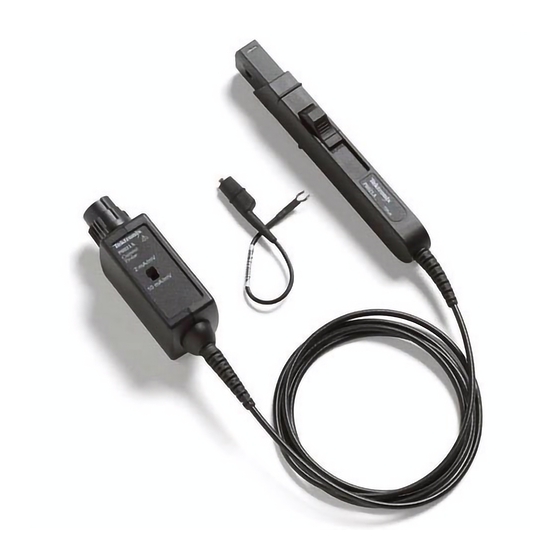
- Page 1 P6021A 60 MHz, 15 Amp AC Current Probe Instruction Manual *P071300400* 071-3004-00...
- Page 3 P6021A 60 MHz, 15 Amp AC Current Probe Instruction Manual www.tektronix.com 071-3004-00...
- Page 4 Copyright © Tektronix. All rights reserved. Licensed software products are owned by Tektronix or its subsidiaries or suppliers, and are protected by national copyright laws and international treaty provisions. Tektronix products are covered by U.S. and foreign patents, issued and pending. Information in this publication supersedes that in all previously published material.
- Page 5 Warranty Tektronix warrants that this product will be free from defects in materials and workmanship for a period of one (1) year from the date of shipment. If any such product proves defective during this warranty period, Tektronix, at its option, either will repair the defective product without charge for parts and labor, or will provide a replacement in exchange for the defective product.
-
Page 7: Table Of Contents
Options ..........................P6021A Current Probe Instruction Manual... - Page 8 Equipment Required ....................... . . P6021A Current Probe Instruction Manual...
- Page 9 Cleaning..........................Index P6021A Current Probe Instruction Manual...
- Page 10 Table of Contents P6021A Current Probe Instruction Manual...
-
Page 11: General Safety Summary
Do not operate without covers. Do not operate this product with covers or panels removed. Do not operate with suspected failures. If you suspect that there is damage to this product, have it inspected by qualified service personnel. P6021A Current Probe Instruction Manual... - Page 12 General safety summary Avoid exposed circuitry. Do not touch exposed connections and components when power is present. Do not operate in wet/damp conditions. Do not operate in an explosive atmosphere. Keep product surfaces clean and dry. P6021A Current Probe Instruction Manual...
- Page 13 These terms may appear on the product: DANGER indicates an injury hazard immediately accessible as you read the marking. WARNING indicates an injury hazard not immediately accessible as you read the marking. CAUTION indicates a hazard to property including the product. P6021A Current Probe Instruction Manual...
- Page 14 General safety summary The following symbol(s) may appear on the product: viii P6021A Current Probe Instruction Manual...
-
Page 15: Service Safety Summary
Dangerous voltages or currents may exist in this product. Disconnect power, remove battery (if applicable), and disconnect test leads before removing protective panels, soldering, or replacing components. To avoid electric shock, do not touch exposed connections. P6021A Current Probe Instruction Manual... -
Page 16: Compliance Information
EN 61010-2-032:2002. Particular requirements for handheld current clamps for electrical measurement and test equipment. U.S. Nationally Recognized Testing Laboratory Listing UL 61010-1 2004, 2 Edition. Standard for electrical measuring and test equipment. IEC 61010-2-032:2002. Particular requirements for handheld current clamps for electrical measurement and test equipment. P6021A Current Probe Instruction Manual... - Page 17 A measure of the contaminates that could occur in the environment around and within a product. Typically the internal environment inside a product is considered to be the same as the external. Products should be used only in the environment for which they are rated. P6021A Current Probe Instruction Manual...
- Page 18 Polution Degree 4. Pollution that generates persistent conductivity through conductive dust, rain, or snow. Typical outdoor locations. Pollution Degree Pollution Degree 2 (as defined in IEC 61010-1). Note: Rated for indoor use only. P6021A Current Probe Instruction Manual...
-
Page 19: Environmental Considerations
This symbol indicates that this product complies with the applicable European Union requirements according to Directives 2002/96/EC and 2006/66/EC on waste electrical and electronic equipment (WEEE) and batteries. For information about recycling options, check the Support/Service section of the Tektronix Web site (www.tektronix.com). -
Page 20: Preface
Preface Preface This manual describes the installation and operation of the P6021A current probe. Basic probe operations and concepts are presented in this manual. You can also access the Tektronix Web site for this document and other related information. Documentation... -
Page 21: Returning The Probe For Servicing
Preface Returning the Probe for Servicing If your probe requires servicing, you must return the probe to Tektronix. If the original packaging is unfit for use or not available, use the following packaging guidelines: Preparation for Shipment 1. Use a corrugated cardboard shipping... -
Page 22: Key Features
Key Features Key Features Use the P6021A current probe to make accurate measurements up to 60 MHz. Key features include: >60 MHz bandwidth, ≤5.8 ns rise time 15 A p-p continuous rating (de-rated with frequency) 250 A peak pulse current (pulse widths <10 μs) -
Page 23: Installation
2. Push in the probe connector and turn it to the right to lock it in place. To disconnect the probe, turn the probe connector to the left and pull the probe away from the instrument. P6021A Current Probe Instruction Manual... -
Page 24: Controls And Indicators
3. The jaw can accept a 5 mm (0.2 in) diameter maximum conductor size. WARNING. To prevent probe damage, do not force conductors larger than 5 mm (0.2 in) diameter into the jaw. P6021A Current Probe Instruction Manual... - Page 25 To prevent probe damage, do not drop the probe or subject it to impact. WARNING. Do not connect the current probe to any wire that carries voltages or currents that exceed the rating of the probes. P6021A Current Probe Instruction Manual...
- Page 26 (range). The correct oscilloscope attenuation settings to use with the P6021A probe are: 2X for the 2 mA/mV range 10X for the 10 mA/mV range P6021A Current Probe Instruction Manual...
-
Page 27: Functional Check
2. Set the oscilloscope to display the probe channel. 3. Clamp the probe to your circuit. 4. Adjust the oscilloscope or use the Autoset function to display a stable waveform. When you see a stable waveform, your probe is functioning correctly. P6021A Current Probe Instruction Manual... -
Page 28: Accessories And Options
1. Fasten the small clip to the ground stub on the probe body. 2. Clip the alligator clip to your circuit ground. 3. Attach the probe to your circuit. Reorder Tektronix part number: 196-3521-xx, qty. 1 P6021A Current Probe Instruction Manual... - Page 29 1. Place the probe, accessories, and manual in the carrying case. 2. Close the carrying case to transport the accessories to another location or for storage. Reorder Tektronix part number: 016-1952-xx P6021A Current Probe Instruction Manual...
- Page 30 The instruction manual provides operating and maintenance instructions. Reorder Tektronix part number: 071-3004-xx Manuals in the languages listed below are available for this product. Other languages may also be available; check the Tektronix Web site at www.tektronix.com/manuals. (Japanese) (Simplified Chinese) P6021A Current Probe Instruction Manual...
-
Page 31: Optional Accessories
fixture fits in the jaw of the current probe. To use the current loop, follow the procedure for the specific task that you are performing (for example, Performance Verification or Adjustments). Order Tektronix part number: 067-2396-xx P6021A Current Probe Instruction Manual... - Page 32 The deskew procedures compensate for gain errors and timing differences between current and voltage probes. Refer to your oscilloscope manual or fixture documentation for instructions. Order Tektronix part number: 067-1686-xx P6021A Current Probe Instruction Manual...
-
Page 33: Options
Option D1. Calibration Data Report Option D3. Calibration Data Report, 3 years (with Option C3) Option D5. Calibration Data Report, 5 years (with Option C5) Option R3. Repair Service 3 years Option R5. Repair Service 5 years P6021A Current Probe Instruction Manual... -
Page 34: Basic Operation
RF currents which can flow into the probe cable. In some cases, it may be helpful to move the ground lead or reposition the probe away from noise sources in the circuit under test. P6021A Current Probe Instruction Manual... - Page 35 1. Clip the ground lead to the ground post at the bottom of the probe head. 2. Connect the alligator end of the clip to the circuit ground. 3. Clamp the probe around the circuit conductor. P6021A Current Probe Instruction Manual...
-
Page 36: Probing Principles
3 mA, the actual current flow is 3 mA divided by 3, or 1 mA. NOTE. Winding more turns around the probe increases the insertion impedance and reduces the upper bandwidth limit of the probe. P6021A Current Probe Instruction Manual... -
Page 37: Common Mode Noise/Magnetic Field Errors
1. Measure on the low or ground side of your circuit. 2. Orient the probe to measure conventional current flow (from positive to negative). NOTE. This method works best when the negative terminal shown in the diagram is tied to earth ground. P6021A Current Probe Instruction Manual... -
Page 38: Maximum Current Limits
) is the maxC maximum current that can be continuously measured at a specified AC frequency. The maximum continuous current value is derated with frequency; as the frequency increases, the maximum continuous current rating decreases. P6021A Current Probe Instruction Manual... - Page 39 The maximum continuous specification varies by frequency. To determine if your measurement exceeds the Ampere-second product, you must first determine the maximum allowable pulse width or maximum allowable pulse amplitude, as described in the following section. P6021A Current Probe Instruction Manual...
- Page 40 The quotient is the maximum allowable pulse width (PW 3. Check that the pulse width at the 50% point of the measured signal is less than the calculated maximum allowable pulse width P6021A Current Probe Instruction Manual...
- Page 41 For example, the P6021A probe has a maximum Ampere-second product of 500 A-μs. If a pulse measured with the probe has a width of 11 μs, the maximum allowable peak current would be 500 A-μs divided by 11 μs, or 45.5 A.
-
Page 42: Application Examples
Application Examples Application Examples This section explains ways to use your probe in common troubleshooting tasks and how to extend the use of your measurement system. P6021A Current Probe Instruction Manual... -
Page 43: Inductance Measurements
3. Clamp the current probe over one of the source leads. NOTE. If the probe impedance is a significant part of the total circuit inductance, measurement accuracy will be affected. Refer to the probe specifications for probe insertion impedance. P6021A Current Probe Instruction Manual... - Page 44 5. Calculate the inductance using the following formula: where: L is the inductance in henries, E is the voltage of the pulse generator, dt is the change in time, and di is the change in current. P6021A Current Probe Instruction Manual...
- Page 45 L is the inductance in henries, τ is the time required for the current to rise or fall 63.2% of the total current value, and R is the source resistance of the pulse generator. P6021A Current Probe Instruction Manual...
-
Page 46: Measuring Inductor Turns Count
3. Clamp the current probe around the inductor and note the current value. The number of turns is equal to the ratio of coil current to input current. The accuracy of this method is limited by the current measurement accuracy. P6021A Current Probe Instruction Manual... - Page 47 The turns are calculated by using the formula: where: is the number of turns in the test coil, is the number of turns in the reference coil, is the measured coil current, and is the input current. P6021A Current Probe Instruction Manual...
-
Page 48: Specifications
The probe must have a warm-up period of at least 20 minutes and be in an environment that does not exceed the limits described. (See Table 1). Specifications for the current probe fall into three categories: warranted, typical, and nominal characteristics. P6021A Current Probe Instruction Manual... -
Page 49: Warranted Characteristics
10 mA/mV: 300 Hz to 60 MHz guaranteed, 150 Hz to 60 MHz typical (20 to 30 °C) 2 mA/mV: >159 μs guaranteed, >355 μs typical (20 to 30 °C) Probe time constant 10 mA/mV: >530 μs guaranteed, >1 ms typical (20 to 30 °C) P6021A Current Probe Instruction Manual... -
Page 50: Typical Characteristics
2 mA/mV: 2.8% or less within 10 μs of step 10 mA/mV: 7.5% or less within 100 μs of step Phase response Between ±90° from 100 Hz to 20 MHz, greater than -270° at 60 MHz P6021A Current Probe Instruction Manual... - Page 51 Maximum voltage on bare wire 150 V CAT lI Maximum voltage on insulated wire 300 V CAT lI Maximum Amp·Second product 500 A·μs (See page 17, Maximum Current Limits.) Figure 1: Frequency derating (continuous peak current versus frequency) P6021A Current Probe Instruction Manual...
- Page 52 Specifications Figure 2: Typical insertion impedance versus frequency P6021A Current Probe Instruction Manual...
- Page 53 Specifications Figure 3: Maximum peak pulse versus pulse width P6021A Current Probe Instruction Manual...
- Page 54 Nonoperating: 5-95% RH, tested up to +30 °C (+86 °F) 5-85% RH, tested at +30 °C to +75 °C (+86 °F to +167 °F) Altitude Operating: Up to 3000 meters (10,000 feet) Nonoperating: Up to 12,192 meters (40,000 feet) P6021A Current Probe Instruction Manual...
- Page 55 Jaw opening (maximum measurable conductor size) 5 mm (0.20 in) Cable length (from probe head to compensation box) 1.5 m (59 in) Unit weight Probe only 279 g ( 10.0 oz) Probe, accessories, and packaging 700 g (1.5 lb) P6021A Current Probe Instruction Manual...
- Page 56 Specifications Figure 4: Mechanical dimensions P6021A Current Probe Instruction Manual...
-
Page 57: Nominal Characteristics
Characteristic Description Input coupling Current range 2 mA/mV: 5 A 10 mA/mV: 15 A Power requirement Supplied by host instrument Termination Terminate output into 1 MΩ Oscilloscope compatibility Oscilloscopes with a 1 MΩ BNC input P6021A Current Probe Instruction Manual... -
Page 58: Performance Verification
The procedures that follow verify the warranted specifications of the probe, listed below. The recommended calibration interval is one year. Midband accuracy Rise time Bandwidth Time constant Perform the following verification procedures in the order listed. P6021A Current Probe Instruction Manual... -
Page 59: Equipment Required
Banana plugs at both ends, lead diameter not to 012-0039-00 exceed 5 mm (0.2 in) Adapter (2) BNC-to-dual banana 103-0090-xx Adapter BNC-T 103-0030-xx Adapter SMA male-to-BNC female 015-1018-xx Nine-digit part numbers (xxx-xxxx-xx) are Tektronix part numbers P6021A Current Probe Instruction Manual... -
Page 60: Equipment Setup
3. Set the oscilloscope coupling to AC. 4. Power on the remaining test equipment. 5. Allow 20 minutes for the equipment to warm up. 6. Photocopy the test record and use it to record the test results. (See page 48.) P6021A Current Probe Instruction Manual... -
Page 61: Midband Accuracy
BNC “T” connector and then connect the other side of the BNC “T” to the DMM input. 3. Connect the middle branch of the BNC “T” connector to the calibration fixture. P6021A Current Probe Instruction Manual... - Page 62 (+) terminal of the current source. 7. Set the probe to the 2 mA/mV range. 8. Set the DMM to the 100 mV range and record the exact measurement of the DMM as M2. P6021A Current Probe Instruction Manual...
- Page 63 14. Record the % Error value in the Test Record. 15. Disable the calibrator output. If the computed % Error is out of the specified limit for either range, the probe may require an adjustment. (See page 49, Adjustments.) P6021A Current Probe Instruction Manual...
-
Page 64: Rise Time And Bandwidth
3. Set the generator output to a 1.0 ns rise time pulse. 4. Set the oscilloscope to display the entire waveform on-screen: Vertical sensitivity to 2 mA/div Horizontal to 20 ns/div Trigger at 20% Averaging on (32) Set Measure to Rise Time P6021A Current Probe Instruction Manual... - Page 65 Bandwidth High Limit 10. Calculate the high frequency limit of the probe for each range setting using the measured rise times in the formula shown: 11. Record the calculated bandwidth limit values in the Test Record. P6021A Current Probe Instruction Manual...
-
Page 66: Time Constant
Probe setup to current, 2X attenuation Vertical sensitivity to 400 mA/div Horizontal to 400 μs/div Trigger at 50% Averaging on (32) Set Measure to Fall Time, High Reference Level to 100%, Low Reference Level to 37% P6021A Current Probe Instruction Manual... - Page 67 4. Calculate the low frequency limit of the probe bandwidth, using the time constant in the formula shown: 5. Record the calculated low frequency limit value for the 2 mA/mV range in the Test Record. P6021A Current Probe Instruction Manual...
- Page 68 7. Set the oscilloscope to: Probe setup to current, 10X attenuation Vertical sensitivity to 500 mA/div Horizontal to 1 ms/div 8. Repeat steps 2 through 5 for the 10 mA/mV range. 9. Disable the generator output. End of procedures. P6021A Current Probe Instruction Manual...
-
Page 69: Test Record
10 mA/mV 5.8 ns Bandwidth (calculated) High limit 60 MHz 2 mA/mV 10 mA/mV 60 MHz Low limit 2 mA/mV 1 kHz 300 Hz 10 mA/mV Time constant 2 mA/mV 159 us 10 mA/mV 530 us P6021A Current Probe Instruction Manual... -
Page 70: Adjustments
Equipment Required Refer to the Performance Verification procedures for the equipment required. You also need a #2 flat-bladed screwdriver and an insulated, flat-bladed adjustment tool. The tool is available from Tektronix; order part number 003-1433-00. P6021A Current Probe Instruction Manual... -
Page 71: Remove The Compensation Box Cover
Use a #2 flat-bladed screwdriver to separate the cover halves to gain access to the adjustments: 1. Insert the screwdriver blade into the slot and gently pry the cable cover away from the compensation box. P6021A Current Probe Instruction Manual... - Page 72 Adjustments 2. Use the screwdriver blade to depress each tab as you separate the cover halves. P6021A Current Probe Instruction Manual...
- Page 73 Adjustments 3. Remove the two halves and then remove the metal shield. P6021A Current Probe Instruction Manual...
-
Page 74: Midband Accuracy
6. Set the probe to the 10 mA/mV range. 7. Adjust the 10 mA/mV control to display 4.0 mV, ±0.12 mV on the DMM. 8. Disconnect the probe from the calibrator and disable the output. P6021A Current Probe Instruction Manual... -
Page 75: Hf Compensation
1. Set up to measure rise time. (See page 43, Rise Time and Bandwidth.) 2. Set the probe to the 2 mA/mV range. 3. Display one waveform cycle. 4. Adjust the HF Comp control in the compensation box for the flattest response. P6021A Current Probe Instruction Manual... - Page 76 HF Comp adjust for optimal rise time and flatness. 6. Set the probe to the 10 mA/mV range and verify performance. If necessary, adjust the probe until risetime passes spec and flatness is acceptable in both ranges. P6021A Current Probe Instruction Manual...
-
Page 77: Maintenance
75% isopropyl alcohol solution and rinse with deionized water. A swab is useful for cleaning narrow spaces on the probe, use only enough solution to dampen the swab or cloth. Do not use abrasive compounds on any part of the probe. P6021A Current Probe Instruction Manual... - Page 78 Maintenance P6021A Current Probe Instruction Manual...
-
Page 79: Index
Cleaning, 56 Functional check, 6 inductance, 22 Common mode noise, 16 inductor turns count, 25 Connect the probe, 2 Current limitations Grounding the probe, 13 amp-second product, 18 Options, 12 maximum continuous, 17 maximum pulsed, 17 P6021A Current Probe Instruction Manual... - Page 80 29 Probe warranted, 28 maximum current limits, 17 saturation, 17 Safety Summary, v Probing principles, 15 Service options, 12 Test record, 48 returning the probe, xv Slider and conductor jaw, 3 Record, test, 48 P6021A Current Probe Instruction Manual...
- Page 81 Mouser Electronics Authorized Distributor Click to View Pricing, Inventory, Delivery & Lifecycle Information: Tektronix P6021A...
Need help?
Do you have a question about the P6021A and is the answer not in the manual?
Questions and answers