Sign In
Upload
Manuals
Brands
Tektronix Manuals
Accessories
GeoProbe G10
Tektronix GeoProbe G10 Manuals
Manuals and User Guides for Tektronix GeoProbe G10. We have
2
Tektronix GeoProbe G10 manuals available for free PDF download: Installation Manual, Hardware Maintenance Manual
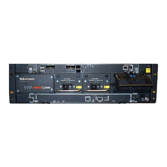
Tektronix GeoProbe G10 Hardware Maintenance Manual (162 pages)
Brand:
Tektronix
| Category:
Accessories
| Size: 5 MB
Table of Contents
What's New in G10 Hardware Version 7.13.2
3
Table of Contents
4
Chapter 1 G10 Probe Overview
9
Overview
9
G10 Probe Configurations
10
G10 Architecture Overview
11
Data Collection and Processing
11
Line Rate Processing-Iris Interface Card (IIC)
12
User Plane and Control Plane Processing-Iris Interface Card (IIC) and Application Blade
12
Storage Subsystem-Store to Disk
12
G10 Hardware Components
13
G10 Front View
13
G10 Rear View
14
Network Connectivity
15
Default Port Settings
16
Time Synchronization
17
G10 Media Probe Configuration
18
G10 Control Plane Probe Configuration
19
Chapter 2 Chassis Subsystem
22
Overview
22
Shelf Manager
23
Rear Panel Leds
24
Rear Panel Connectors
25
Power Entry Modules (Pems)
26
DC Pems
26
Front Panel Leds
27
AC Pems
28
Front Panel Leds
28
Fan Trays
29
Electro-Static Discharge Points
30
Chapter 3 Blades and Rtms
31
Overview
31
Iris Interface Card
32
IIC Leds
32
Iic200
34
IIC200 Leds
34
Fpc200 Amc
35
Lpc200 Amc
37
IIC200 Rtms
39
Iic100
42
Fpc100 Amc
43
Lpc100 Amc
45
IIC100 Rtms
46
Applications Blade
53
Iap320/Iap200
54
Iap320
55
Iap200
58
Prm300 Rtm/Prm200 Rtm
60
Iap100
63
IAP100 Leds
64
IAP100 Connectors
65
Sas Amc
66
IAP100 Rtms
67
Interconnect Card
70
10G Interconnect Card Leds
71
10G Interconnect Card Connectors
72
G10 Hardware Component Name Reference
72
Chapter 4 Storage Subsystem
74
SAS Storage Arrays
74
Supported Models
75
Storage Enclosure Features
75
Disk Enclosure Front Panels
77
SA100R, SA100J, SA200R, and SA200J Front Panel
77
SA210J Front Panel
77
Front Panel Leds
78
Disk Enclosure Rear Panel
79
SA200R Controller Enclosure Rear Panel
79
SA200R Controller Enclosure Connectors
81
SA100R Controller Enclosure Rear Panel
81
SA100R Controller Enclosure Connectors
83
SA100J, SA200J, and SA210J Expansion Enclosure Rear Panel
84
Expansion Enclosure Connectors
85
Chapter 5 Maintenance Guidelines
86
Overview
86
G10 Maintenance Procedures
87
Field Replaceable Units
87
Removing and Replacing a PEM
89
Replacing a DC PEM
89
Replacing an AC PEM
91
Replacing the Fan Tray
94
Replacing G10 Chassis Air Filters
97
Replacing the Top Air Filter
97
Replacing the Bottom Air Filter
99
G10 Blade Removal/Replacement Procedures
102
Iap100
102
Sas Amc (Iap100)
105
Iap200/Iap320
106
Iris Interface Card (IIC100 or IIC200)
108
LPC and FPC Amcs (IIC100 or IIC200)
115
Rtms
116
10G Interconnect Card
118
Replacing G10 Shelf Managers (Shmms)
120
Replacing the First (Standby) SHMM
120
Replacing the Second (Active) SHMM
121
Serial over LAN (SOL) Support
122
G10 Probe and Array Start Up/Shut down Sequence
122
Start up Procedure
122
Shut down Procedure
124
Storage Array Maintenance Procedures
125
Storage Array Maintenance Guidelines
125
Replacing a Power Supply
126
Removing the Power Supply
126
Installing the Power Supply
128
Bezel (Air Filter) Procedures
129
Installing the Bezel
129
Removing the Air Filter
130
Replacing the Air Filter
132
Replacing a Controller or Expansion Module
134
Removing the Controller Module
134
Installing the Controller Module
136
Replacing a Drive Module
137
Removing Air Management Modules
137
Installing Drive Modules
138
Replacing the Disk Array Chassis
139
Removing the Disk Array Chassis
140
Installing the Disk Array Chassis
141
Chapter 6 System Operating Specifications
143
Overview
143
Physical Specifications
144
Power and Ground Requirements
145
DC Power Requirements
145
AC Power Requirements
146
Environmental Specifications
147
Regulatory Specifications
147
Safety Compliance
147
EMC Standards
148
CE Mark
149
Nebs
149
ETSI Compliance
149
Safety Guidelines
150
Equipment Use
150
Handling the Geoprobe G10
150
Damage to Circuits
150
Geoprobe G10 Power Disconnect
150
Circuit Protection
151
FP100 Fuse Panel
151
G10 Equipment Warning Labels
153
Appendix Asfp Reference
154
Monitored Ports Sfps
154
Gb Port Sfps
155
1000Base-LX Fiber
155
1000Base-SX Fiber
156
1000Base-T Copper
156
Gb Port Sfps
157
10Gbase-SR Fiber
158
10Gbase-LR Fiber
158
Minimum Signal Levels
158
Installing Sfps
159
Iic200
160
Iic100
161
Trm100 Rtm
161
PRM200 RTM or PRM300 RTM
162
Srm200 Rtm
162
Advertisement
Tektronix GeoProbe G10 Installation Manual (168 pages)
Probe / Network Monitor
Brand:
Tektronix
| Category:
Measuring Instruments
| Size: 6 MB
Table of Contents
What's New in G10 Probe 7.13.2
3
Table of Contents
4
G10 New Installation and Upgrade Workflows
8
Chapter 1 G10 New Installation and Upgrade Workflows
9
G10 New Installation Workflow
10
G10 Upgrade Workflow
10
Upgrade Iris Server and Probe Software
11
Upgrade Applications Blade (IAP)
11
Upgrade IIC Blade
12
Configure Probe Setup
15
Power on G10 Probe
15
Probe Setup
15
Irisview OAM Configuration Updates
15
IAP Rollback Option
15
IIC100 Rollback Option
16
Install Hardware and Power Cabling
17
Before You Begin
17
G10 Hardware Installation Workflow
18
Chapter 2 Install Hardware and Power Cabling
18
Install G10 Chassis
19
Four-Post Rack, Front Mount
19
Two-Post Rack, MID Mount
24
Install Storage Enclosures
26
Four-Post Rack, Front Mount
26
Two-Post Rack, MID Mount
32
Install Fuse Panel
35
Four-Post Rack, Front Mount
35
Two-Post Rack, MID Mount
36
Connect Power Cabling
38
G10 Probe Power Cabling
38
AC Units
38
DC Units
39
Storage Enclosure Power Cabling
40
AC Units
40
DC Units
41
Fuse Panel Power Cabling (DC Units Only)
42
Terminal and Wiring Recommendations
45
G10 Hardware Component Name Reference
45
Connect Ethernet and SAS Cabling
47
Cabling Summary
47
IIC200 + IAP200/IAP320 Ethernet and SAS Cabling
48
Connect Ethernet Cabling
48
Chapter 3 Connect Ethernet and SAS Cabling
48
Connect SAS Cabling (IIC200 + IAP200/IAP320)
50
SRM200 RTM SAS Connections (One or Two Controllers)
50
TRM100 RTM SAS Connections (One or Two Controllers)
52
Controller Enclosure to Expansion Enclosures SAS Connections
53
IIC100 + IAP200 Ethernet and SAS Cabling
54
Connect IIC100 + IAP200 Ethernet Cabling
54
Connect IIC100 + IAP200 SAS Cabling
56
Controller Enclosure to Expansion Enclosures SAS Connections
57
IIC100/IIC200 + IAP100 Ethernet and SAS Cabling
58
Connect IIC/IAP100 Ethernet Cabling
58
Connect IIC/IAP100 SAS Cabling
60
SRM200 RTM SAS Connections
60
TRM100 RTM or SRM100 RTM SAS Connections
61
Chapter 4 Power on G10 and Configure Network Connectivity
62
Power on the System
62
Configure G10 Probe Network Connectivity
68
Network Connectivity Parameters
74
Chapter 5 Connect G10 to the Monitored Network
76
Monitored Link Support
76
Monitored Link Cabling (IIC200)
77
IIC200 Ethernet Connections
77
Optical Taps/Splitters (IIC200)
78
Mirror/Span Ports (IIC200)
80
Monitored Link Cabling (IIC100)
82
Gigabit Ethernet Connections (IIC100)
82
Ethernet Cabling for Optical Taps/Splitters (IIC100)
83
1G Ethernet Cabling for Mirror/Span Ports
85
Gigabit Ethernet Connections (TRM100 RTM)
86
10G Ethernet Cabling for Optical Taps/Splitters
87
10G Ethernet Cabling for Mirror/Span Ports
89
Appendix A G10 Operating Specifications
91
Overview
91
Rack Space Considerations
92
Example Rack Installations
93
DC Power Requirements
96
AC Power Requirements
96
Default Port Settings
97
Appendix Bsfp Reference
98
Overview
98
Gb Port Sfps
99
1000Base-LX Fiber
100
1000Base-SX Fiber
100
1000Base-T Copper
100
Gb Port Sfps
101
10Gbase-SR Fiber
102
10Gbase-LR Fiber
102
Minimum Signal Levels
102
Installing Sfps
103
Iic200
104
Iic100
105
Trm100 Rtm
105
PRM200 RTM or PRM300 RTM
106
Srm200 Rtm
106
Appendix C Maintenance Guidelines
107
Overview
107
G10 Maintenance Procedures
108
Field Replaceable Units
108
Removing and Replacing a PEM
110
Replacing a DC PEM
110
Replacing an AC PEM
112
Replacing the Fan Tray
115
Replacing G10 Chassis Air Filters
118
Replacing the Top Air Filter
118
Replacing the Bottom Air Filter
120
G10 Blade Removal/Replacement Procedures
123
Iap100
123
Sas Amc (Iap100)
126
Iap200/Iap320
127
Iris Interface Card (IIC100 or IIC200)
129
LPC and FPC Amcs (IIC100 or IIC200)
136
Rtms
137
10G Interconnect Card
139
Replacing G10 Shelf Managers (Shmms)
141
Replacing the First (Standby) SHMM
141
Replacing the Second (Active) SHMM
142
Serial over LAN (SOL) Support
143
G10 Probe and Array Start Up/Shut down Sequence
143
Start up Procedure
143
Shut down Procedure
145
Storage Array Maintenance Procedures
146
Storage Array Maintenance Guidelines
146
Replacing a Power Supply
147
Removing the Power Supply
147
Installing the Power Supply
149
Bezel (Air Filter) Procedures
150
Installing the Bezel
150
Removing the Air Filter
151
Replacing the Air Filter
153
Replacing a Controller or Expansion Module
155
Removing the Controller Module
155
Installing the Controller Module
157
Replacing a Drive Module
158
Removing Air Management Modules
158
Installing Drive Modules
159
Replacing the Disk Array Chassis
160
Removing the Disk Array Chassis
161
Installing the Disk Array Chassis
162
Appendix D G10 NEBS Requirements
164
Overview
164
G10 Probe Signal Port Requirements
164
Storage Enclosure Bonding and Grounding Requirements
165
Equipment Cooling Requirements
168
Advertisement
Related Products
Tektronix Grass Valley 4000
Tektronix GTS1063
Tektronix GTS1250
Tektronix 010-0211-00
Tektronix 010-0212-00
Tektronix 010-0217-00
Tektronix 010-0218-00
Tektronix 070-4431-01
Tektronix CT-6
Tektronix P5200A
Tektronix Categories
Test Equipment
Measuring Instruments
Amplifier
Portable Generator
Printer
More Tektronix Manuals
Login
Sign In
OR
Sign in with Facebook
Sign in with Google
Upload manual
Upload from disk
Upload from URL