Table of Contents
Advertisement
COMFORT CONTROL CENTER 2 THERMOSTAT
OPERATING INSTRUCTIONS
PROGRAMMABLE THERMOSTAT
MODEL
3314080.000 BLACK
3314080.015 WHITE
USA
CANADA
For Service Center &
SERVICE OFFICE
Dometic Corporation
Dealer Locations
Dometic Corporation
46 Zatonski, Unit 3
Please Visit:
1120 North Main Street
Brantford, ON N3T 5L8
www.eDometic.com
Elkhart, IN 46514
CANADA
REVISION B
Form No. 3314149.018 08/16
(French 3314169.016_B)
©2016 Dometic Corporation
LaGrange, IN 46761
Advertisement
Table of Contents

Related Manuals for Dometic 3314080.000 BLACK


Summary of Contents for Dometic 3314080.000 BLACK
- Page 1 COMFORT CONTROL CENTER 2 THERMOSTAT OPERATING INSTRUCTIONS PROGRAMMABLE THERMOSTAT MODEL 3314080.000 BLACK 3314080.015 WHITE CANADA For Service Center & SERVICE OFFICE Dometic Corporation Dealer Locations Dometic Corporation 46 Zatonski, Unit 3 Please Visit: 1120 North Main Street Brantford, ON N3T 5L8 www.eDometic.com...
-
Page 2: Table Of Contents
INTRODUCTION Congratulations! Your recreational vehicle manufacturer has equipped your RV with the most advanced RV thermostat. Your Dometic Comfort Control Center 2 thermostat (hereinafter referred to as the CCC 2 thermostat) has been designed for ease of opera- tion and for many years of reliable service. Dometic Corporation reserves the right to modify appearances and specifications without notice. TABLE OF CONTENTS INTRODUCTION ............................2 DOCUMENT SYMBOLS ..........................3 ABOUT YOUR NEW THERMOSTAT ......................3 Features ............................ -
Page 3: Document Symbols
TABLE OF CONTENTS Reduce Heat Gain ........................19 Disclaimer ..........................19 MAINTENANCE ............................20 Air Filter ...........................20 Dometic CCC 2 Thermostat ....................20 SERVICE ..............................20 DOCUMENT SYMBOLS Indicates additional information that is not related to personal injury. Indicates step-by-step instructions. ABOUT YOUR NEW THERMOSTAT A. Features ● Liquid Crystal Display ● Two operation programs ● Constant time of day display ●... - Page 4 / “AQUA” - Furnace Or Aqua (Hydronic) Heating Mode” on page (11). Any time a system reset occurs, the factory default settings are restored. See table, “Factory Preset Settings” on page (4). In the unlikely event of CCC 2 system memory loss or dip switch setting change, the CCC 2 thermostat will require a system reset. For system reset procedure, see main heading, “System Reset Procedure” on page (19). Your Dometic CCC 2 thermostat has been pre-programmed. Review settings below and adjust the settings to your personal comfort level. Any time the CCC 2 is in an idle stage (not illuminated) you will need to wake it up by pressing any button on the CCC 2 before it will recognize a new setting attempt. Factory Preset Settings Factory Preset Settings Each Zone All Zones Program “1”...
-
Page 5: Quick Reference To Control Buttons
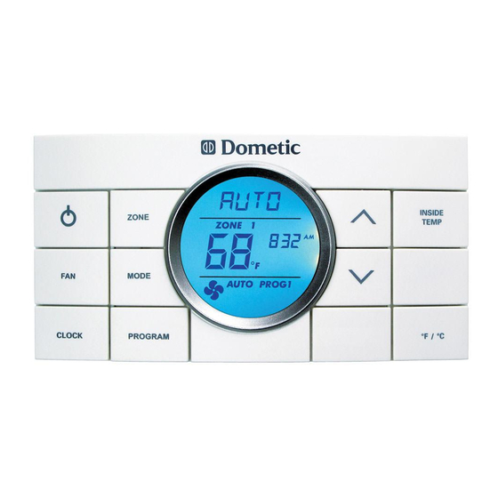
ABOUT YOUR NEW THERMOSTAT C. Quick Reference To Control Buttons Press to increase Press to select zone temperature set-point Press to display Press to select inside temperature On and OFF Press to select Press to select temperature format fan speed Press to set clock Press to decrease... -
Page 6: Programming & Operations
PROGRAMMING & OPERATIONS A. ON/OFF To turn ON the CCC 2 thermostat when the back light is OFF, first press any button to wake up the CCC 2 thermostat. Then press and release the ON/OFF button. The LCD will display the last programmed settings. To turn OFF the CCC 2 thermostat press the ON/OFF button and release. Only the time of day will display when the CCC 2 thermostat is in the OFF condition. B. Clock Setting Press the CLOCK button to initiate the clock setting sub-menu on the CCC 2 ther- mostat. When in this menu, the hour digits will flash first. The hour can be adjusted using the ∧ or ∨ buttons. Press the CLOCK button again and the minute digits will flash, allowing the minute setting to be adjusted using the ∧... -
Page 7: Temperature Format °F / °C
PROGRAMMING & OPERATIONS C. Temperature Format °F / °C Press the °F / °C button to switch between Fahrenheit and Centigrade format. “°F” indicates Fahrenheit and “°C” indicates Centigrade. D. Inside Temperature Press and hold the INSIDE TEMP button and the LCD will display the current inside temperature recorded at the CCC 2 thermostat (or at the optional remote indoor temperature sensor) instead of the temperature set-point. The LCD will also display “IN” to indicate that the inside temperature is being displayed. When the INSIDE TEMP button is released, the LCD will return to the programmed temperature set- point. -
Page 8: Zone Selection
PROGRAMMING & OPERATIONS E. Zone Selection Press the ZONE button to cycle the LCD display through the available zone selec- tions; “Zone 1”, “Zone 2”, “Zone 3”, and “Zone 4”. Only the available zones installed within your system will display. For more information on zones, see section, “B. Zone Control” on page (13). F. Mode Selection Press the MODE button and the LCD will display the first available mode. Each successive press will advance to the next available mode. Continue to press the MODE button until the desired mode appears. Depending on the systems installed, your choices will be “OFF”, “COOL”, “AUTO”, “HP”, “FURN” or “AQUA”, “HS”, and... -
Page 9: Fan Speed
PROGRAMMING & OPERATIONS G. Fan Speed Press the FAN button to select the desired fan speed. Each successive press will advance to the next available speed. Your selections will be “Auto”, “LOW”, “MED”, and “HIGH”. The fan will run continuously during “LOW”, “MED”, and “HIGH” fan settings. The fan will cycle ON and OFF with the thermostat on “AUTO” setting. For more information on auto fan, see section, “A. Auto Fan” on page (12). H. Temperature Set-Point Press the ∧ or ∨ button to change the temperature set-point. The temperature set-point is indicated by (2) digits on the LCD. -
Page 10: Mode Description
MODE DESCRIPTION A. “OFF” - Off Mode Displays OFF mode in a zone. B. “COOL” - Cool Mode In the COOL mode the system will cycle the compressor ON and OFF based on the room air temperature and the temperature set-point on the CCC 2 thermostat. When the system calls for cooling there will be a delay of approximately 2 minutes. During this delay, the hour glass icon will be displayed in the LCD. In auto fan, the fan will turn ON first followed by the compressor in approximately 15 seconds. In this mode there are (4) fan speed selections: LOW: The fan operates continuously at low speed. The compressor cycles ON and OFF. MED: The fan operates continuously at medium speed. The compressor cycles ON and OFF. HIGH: The fan operates continuously at high speed. The compressor cycles ON and OFF. -
Page 11: Hs" - Heat Strip Mode
MODE DESCRIPTION D. “HS” - Heat Strip Mode In the HS mode the system will cycle the heat strip ON and OFF based on the room air temperature and the temperature set-point on the CCC 2 thermostat. In this mode there are (4) fan speed selections: LOW: The fan operates continuously at low speed. The heat strip cycles ON and OFF. MED: The fan operates continuously at medium speed. The heat strip cycles ON and OFF. HIGH: The fan operates continuously at high speed. The heat strip cycles ON and OFF. AUTO: The fan operates in low speed and will cycle ON and OFF with the thermo- stat. E. “FAN” - Fan Mode In FAN mode there are (4) fan speed selections: LOW: The fan operates continuously at low speed. -
Page 12: Auto" - Auto Change Over Mode
MODE DESCRIPTION G. “AUTO” - Auto Change Over Mode In the AUTO mode the system will automatically change the mode of operation from cool to heat or from heat to cool. In order for this mode to operate, the zone being programmed must contain either a heat pump, heat strip or furnace heating source. When in the AUTO mode, all pre-programmed operations for the heat pump, heat strip, and furnace will apply. Auto Change Over Cooling: If the room temperature rises above the temperature set-point by 2 °F / °C, the air conditioner will turn ON until the room temperature reaches the temperature set-point at which time the air conditioner will cycle OFF. -
Page 13: Zone Control
B. Zone Control Zones are established at the time of the installation of your Dometic CCC 2 thermo- stat. A zone is an area of cooling/heating which is controlled independently by the CCC 2 thermostat. The CCC 2 thermostat allows for four zones (Air Conditioner/ Heat Pump) to be set up and run independent of each other. If you have one air conditioner/heat pump installed, you will have one zone. If your RV has more than one cooling/heating system, you may have two, three, or four zones. Your CCC 2 thermostat will operate cooling and heating appliances that your vehicle manufacturer has designed to cool or heat specific areas (zones) of your RV. The CCC 2 thermostat will advise you of the number of zones in your RV. The zones are displayed “1”, “2”, “3”, or “4” in the LCD readout. See section, “D. Quick Reference To LCD Icons” on page (5). In the event your vehicle has multiple zones designed, you have the freedom of selecting different modes of operations for each zone. To change from one zone to... - Page 14 SPECIAL FEATURES When program “1” or “2” is operating, the “PROG 1” or “PROG 2” icon will be dis- played in the LCD. The zone will continue to operate in the programmed setting until the program is manually cancelled. To cancel the program operation, press and hold the PROGRAM button for 3 sec- onds. The zone will be restored to normal operation.
-
Page 15: Examples Of Times Programmed
SPECIAL FEATURES D. Examples Of Times Programmed E. CANbus Interface The CANbus interface is designed to communicate between the Dometic CCC 2 thermostat and a CAN (Controller Area Network) protocol generator. Refer to the CANbus installation instructions for more information on installation and operation of the CANbus. -
Page 16: Auxiliary Heat (Heat Pump Models Only)
H. Stage Select - Dual Compressor Air Conditioner/Heat Pump (Select Models) The Dometic CCC 2 thermostat will operate an air conditioner/heat pump unit with two compressors. On dual basement air conditioner/heat pump units, a single pow- er module board is used to control the operation of two compressors in one air conditioner/heat pump. This system is designed to optimize comfort and operating efficiency by providing an on-demand secondary stage of operation. The CCC 2 thermostat will allow the user to set the primary temperature set-point. The set-point... -
Page 17: Auto Generator Start (Ags)
When a zone calls for heating or cooling, the AGS relay shall be closed, followed by a time delay to allow the generator to warm up after which time the output relay will be activated on the zone that initiated the heating or cooling request. When the heat/cool requests in all zones have been satisfied, the AGS relay will open and the generator will shut-down. J. Load Shed The Dometic CCC 2 thermostat has provisions for Load Shedding. The AC pow- er module board shall provide the 12 Vdc source for the Load Shed signal. This 12 Vdc source shall be turned ON 1 second before the compressor relay when the system calls for the compressor to be ON. The Load Shed source shall remain ON when compressor is caused to turn OFF due to being disable by either a Freeze Sensor or a Load Shed condition. The load shed source signal will be switched to the Load Shed input by the normally open contacts or an off-board relay from the RV power management system. When the Load Shed signal is detected, the compres- sor shall turn OFF. K. Defrost Cycle (Heat Pump Models Only) To avoid frost formation on the outside coil and to obtain maximum performance when the outside temperature is less than 42 °F (6 °C) and greater than 30 °F... -
Page 18: Power Interruption
SPECIAL FEATURES M. Power Interruption In the event the power to the air conditioner or control is interrupted, the system will restart with the previous set points once power is restored. N. LCD Error Code When the system determines that one of the faults listed below has occurred an er- ror code will be displayed in the LCD for the zone in which the error occurred. During normal operation, a blinking zone number indicates a fault has occurred. The error code is displayed in place of the temperature set-point. Error Code: E1 Loss of communication between the CCC 2 thermostat and all system power module boards. System will shut down. E1 Loss of communication between the CCC 2 thermostat and an individual system power module board. The LED will display error code “E1” and the zone number that lost communication. Any additional zones that loose communication will blink in addition to the current zone. E2 Open circuit or out-of-range Indoor Temperature Sensor. All heat and cool op- eration will be locked out. Manual fan operation will continue. E3 Shorted Indoor Temperature Sensor. All heat and cool operation will be locked out. Manual fan operation will continue. E4 Open circuit or out of range Outdoor Temperature Sensor (select models). Heat pump operation will be locked out. Air conditioner, furnace, heat strip, and fan operation can continue to operate. -
Page 19: System Reset Procedure
● K eeping windows and doors shut or minimizing usage. ● A voiding the use of heat producing appliances. Operation on High Fan/Cooling mode will give optimum or maximum efficiency in high humidity or high outside temperatures. Starting the air conditioner early in the morning and giving it a “head start” on the expected high outdoor ambient will greatly improve its ability to maintain the desired indoor temperature. For a more permanent solution to high heat gain, accessories like Dometic outdoor patio and window awnings will reduce heat gain by removing the direct sun. They also add a nice area to enjoy company during the cool of the evening. B. Disclaimer The manufacturer of this unit will not be responsible for damage caused by con- densation forming on ceilings, windows, or other surfaces. Air contains water vapor which condenses when temperature of a surface is below Dew point. During normal operation this unit is designed to remove a certain amount of moisture from the air, depending on the size of the space being conditioned. Keeping doors and windows... -
Page 20: Maintenance
LCD. (See section, “D. Quick Reference To LCD Icons” on page (5).) When this occurs wash the filter with soap and warm water. Let dry and reinstall. To reset the fan run time and clear the filter icon, hold the INSIDE TEMP and °F / °C buttons for 3 seconds. This will clear the fan run time for the current zone selected. B. Dometic CCC 2 Thermostat D O NOT spray water directly on the CCC 2 thermostat. DO NOT use solvents for cleaning. Clean the CCC 2 thermostat with a moist soft cloth. SERVICE In the unlikely event the unit fails to operate or operates improperly, check the fol- lowing before calling your service center.
Need help?
Do you have a question about the 3314080.000 BLACK and is the answer not in the manual?
Questions and answers