Table of Contents
Advertisement
Quick Links
Advertisement
Table of Contents

Related Manuals for Gossen MetraWatt mavolog pro


Summary of Contents for Gossen MetraWatt mavolog pro
-
Page 4: Table Of Contents
Description of the MAVOLOG PRO Power Quality Analyzer .......... 7 Abbreviation/Glossary ....................8 Purpose and use of the MAVOLOG PRO Power Quality Analyzer ........ 10 Device application and benefits ................... 11 Main Features, supported options and functionality of MAVOLOG PRO Power Quality analyzer ...................... - Page 5 MAVOLOG PRO – Waveform and Transient Recorder CONTENTS Data analysis ........................37 My Devices ........................37 Upgrade .......................... 37 Software upgrading ......................38 Setting procedure ......................40 General Settings ......................41 Description & Location ....................41 Average interval ......................41 Language .........................
- Page 6 CONTENTS MAVOLOG PRO – Waveform and Transient Recorder LCD navigation ........................ 55 Display .......................... 56 Contrast/Black light intensity ..................56 Saving mode (min) ......................56 Demo cycling period (sec) ....................56 Custom screen 1/2/3 ....................... 56 LCD navigation ........................ 57 Security .........................
- Page 7 MAVOLOG PRO – Waveform and Transient Recorder CONTENTS Pushing time delay ......................70 Alarms group settings ..................... 70 Alarm statistics reset ....................... 70 MD Time constant (min) ....................70 Compare time delay (sec) ....................70 Hysteresis (%) ........................70 Response time ......................... 71 Individual alarm settings ....................
- Page 8 Harmonic analasis – MAVO-View ................. 131 PQ Analysis ......................... 134 LCD navigation ......................142 PQDIF and COMTRADE files on MAVOLOG PRO – concept description ..... 143 Working with PQDIF and COMTRADE files on the device .......... 143 Accessing PQDIF files ..................... 143 Accessing COMTRADE files ....................
- Page 9 MAVOLOG PRO – Waveform and Transient Recorder CONTENTS APPENDIX E: PQDIF and COMTRADE recorder data storage organization ....188 APPENDIX F: IEC61850 protocol support overview ............ 191 GMC-I Messtechnik GmbH...
-
Page 10: Power Quality Analyzer Mavolog Pro
MAVOLOG PRO – Waveform and Transient Recorder MAVOLOG PRO - Waveform and Transient Recorder (Feature H01) MAVOLOG PRO with Feature H01 GMC-I Messtechnik GmbH... -
Page 11: Warnings, Information And Notes Regarding Designation Of Product
MAVOLOG PRO – Waveform and Transient Recorder WARNINGS, INFORMATION AND NOTES REGARDING DESIGNATION OF PRODUCT Used symbols: See product documentation. Double insulation in compliance with the EN 61010−1 standard. Functional ground potential. Note: This symbol is also used for marking a terminal for protective ground potential if it is used as a part of connection terminal or auxiliary supply terminals. -
Page 12: Before Switching The Device On
MAVOLOG PRO – Waveform and Transient Recorder BEFORE SWITCHING THE DEVICE ON Check the following before switching on the device: Nominal voltage, Supply voltage, Nominal frequency, Voltage ratio and phase sequence, Current transformer ratio and terminals integrity, ... -
Page 13: Health And Safety
MAVOLOG PRO – Waveform and Transient Recorder HEALTH AND SAFETY The purpose of this chapter is to provide a user with information on safe installation and handling with the product in order to assure its correct use and continuous operation. -
Page 14: Disposal
MAVOLOG PRO – Waveform and Transient Recorder DISPOSAL It is strongly recommended that electrical and electronic equipment is not deposit as municipal waste. The manufacturer or provider shall take waste electrical and electronic equipment free of charge. The complete procedure after lifetime should comply with the Directive 2012/19/EU about restriction on the use of certain hazardous substances in electrical and electronic equipment. -
Page 15: Basic Description And Operation
More detailed description of device functions is given in chapters Main Features, Supported options and Functionality. The MAVOLOG PRO Advanced Power Quality Analyzer is available in 144 mmx144 mm panel mounting enclosure. Specifications of housing and panel cut out for housing is specified in chapter Contents Contents and size of a packaging box can slightly vary depending on type of consignment. -
Page 16: Description Of The Mavolog Pro Power Quality Analyzer
MAVOLOG PRO – Waveform and Transient Recorder Description of the MAVOLOG PRO Power Quality Analyzer The MAVOLOG PRO Advanced Power Quality Analyzer is a comprehensive device intended for permanent monitoring of power quality from its production, transmission, distribution all the way to the final consumers, who are most affected by inadequate voltage quality. -
Page 17: Abbreviation/Glossary
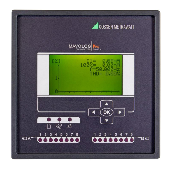
MAVOLOG PRO – Waveform and Transient Recorder Appearance 1 – Graphical LCD 2 – Navigation keyboard 3 – General operation LED indicators (clock synchro./comm./alarm) 4 – I/O status LED indicators Graphical LCD: A graphical LCD with back-light is used for displaying measuring quantities and for a display of selected functions when setting the device. - Page 18 MAVOLOG PRO – Waveform and Transient Recorder by harmonics) THD (U, I) Total harmonic distortion Total demand distortion (according to IEEE Std. 519-1992). Indicates TDD (I) harmonic distortion at full load. Indicates a weighting of the harmonic load currents according to K factor (I) their effects on transformer heating.
-
Page 19: Purpose And Use Of The Mavolog Pro Power Quality Analyzer
This can be achieved with regard to MAVOLOG PRO accurate internal real time clock and wide range of synchronization sources support, which assure accurate, time-stamped measurements from dislocated units. -
Page 20: Device Application And Benefits
Therefore the most extensive benefits are achieved when the MAVOLOG PRO is used as a part of a PQ monitoring system comprising of strategically positioned meters connected to the MAVO-Database software solution. -
Page 21: Main Features, Supported Options And Functionality Of Mavolog Pro Power Quality Analyzer
Main Features, supported options and functionality of MAVOLOG PRO Power Quality analyzer MAVOLOG PRO Advanced Power Quality Analyzer is a perfect tool for monitoring and analyzing medium or low voltage systems in power distribution and industrial segments. It can be used as a standalone PQ monitoring device for detection of local PQ deviations. - Page 22 MAVOLOG PRO – Waveform and Transient Recorder o Four quadrant energy measurement in 8 programmable counters with class 0.2S accuracy with up to four tariffs and an advanced tariff clock. Every Counters’ resolution and range can be defined. The counter content can be configured as: ...
- Page 23 MAVOLOG PRO – Waveform and Transient Recorder General hardware Features Default / Optional General ● Class A measuring accuracy (0.1%) according to EN 61000-4-30 Ed.3 ● Voltage auto range up to 1000Vp-p ● Current auto range up to 12.5 A ●...
- Page 24 MAVOLOG PRO – Waveform and Transient Recorder General hardware Features Default / Optional Input and output modules Input / output module 1 2×AO / 2×AI / 2×RO / 2×PO / 2×PI / 2×TI / 1×BO / 2×DI / WO+RO ○/○/○/○/○/○/○/○/○...
- Page 25 MAVOLOG PRO – Waveform and Transient Recorder General software Features Default / Optional ● EN 50160 power quality evaluation ● Automatic PQ report generation ● Disturbance, trend & PQ event recording Waveform recorder with programmable sampling time ● (max 625 samples / period) ●...
-
Page 26: Connection
Connection shall therefore be performed ONLY a by a qualified person using an appropriate equipment. GOSSEN METRAWATT d.d. does not take any responsibility regarding the use and connection. If any doubt occurs regarding connection and use in the system which device is intended for, please contact a person who is responsible for such installations. -
Page 27: Mounting
MAVOLOG PRO – Waveform and Transient Recorder Mounting MAVOLOG PRO Advanced Power Quality Analyzer is intended only for panel mounting. Pluggable connection terminals allow easier installation and quick replacement should that be required. This device is not intended for usage as portable equipment and should be used only as a fixed panel mounted device. -
Page 28: Electrical Connection For Mavolog Pro Power Quality Analyzer
MAVOLOG PRO – Waveform and Transient Recorder Electrical connection for MAVOLOG PRO Power Quality Analyzer Voltage inputs of a device can be connected directly to low-voltage network or via a voltage measuring transformer to a high-voltage network. Current inputs of a device are led through a hole in current transformers to allow uninterrupted current connection. - Page 29 MAVOLOG PRO – Waveform and Transient Recorder Connection 3u (2W3) Three-phase – three-wire connection with unbalanced load Connection 4b (1W4) Three-phase – four-wire connection with balanced load Connection 4u (3W4) Three-phase – four-wire connection with unbalanced load PLEASE NOTE With all connection schemes must be terminal 12 (PE) ALWAYS connected. Fourth voltage channel is dedicated for measuring voltage between EARTH (PE, terminal 12) and NEUTRAL (N, terminal 11).
-
Page 30: Connection Of Input/Output Modules
MAVOLOG PRO – Waveform and Transient Recorder Connection of input/output modules WARNING! Check the module features that are specified on the label, before connecting module contacts. Wrong connection can cause damage or destruction of module and/or device. PLEASE NOTE Examples of connections are given for device with built in two input/output modules and Ethernet/USB communication. - Page 31 MAVOLOG PRO – Waveform and Transient Recorder I/O module 1 and 2 (terminal numbers 15-20) – input options Tariff input module with two tariff inputs for changeover between up to four tariffs. Digital input module with two digital inputs enables reception of impulse signals.
- Page 32 MAVOLOG PRO – Waveform and Transient Recorder Synchronization module C Synchronization module is equipped with support for two different synchronization methods IRIG-B and GPS modem. When modulated IRIG-B signal is used it should be connected to BNC terminal. When level-shift IRIG-B signal is used it should be connected to 1PPS terminal.
-
Page 33: Communication Connection
MAVOLOG PRO – Waveform and Transient Recorder Communication connection Primary communication interface (COM1) type is normally specified when placing an order. Device supports Ethernet communication designed as standard RJ-45 terminal and USB communication designed as standard USB-B type terminal Beside primary communication port the device has built in a secondary communication port (COM2) as a part of a real time synchronization module C. - Page 34 MAVOLOG PRO – Waveform and Transient Recorder IRIG time code B (IRIG-B): Unmodulated (DC 5V level shift) and modulated (1 kHz) serial coded format with support for 1pps, day of year, current year and straight seconds of day as described in standard IRIG-200-04. Supported serial time code formats are IRIG-B007 and IRIG-B127 Interface for modulated IRIG-B is designed as BNC-F terminal with 600 Ohm input impedance.
-
Page 35: Connection Of Aux. Power Supply
MAVOLOG PRO – Waveform and Transient Recorder Connection of aux. Power supply Device can be equipped with either of two types of universal (AC/DC) switching power supply. 80...300 V DC Feature A00 (Standard): 80...276 V AC; 40...65 Hz 19...70 V DC Feature A01 (no longer aivailable): 48...77 V AC;... -
Page 36: First Steps
MAVOLOG PRO – Waveform and Transient Recorder FIRST STEPS Programming device is very transparent and user friendly. Numerous settings are organized in groups according to their functionality. Programming device can be performed using the keypad and display on the front panel. Due to representation of certain settings not all settings can be programmed this way. - Page 37 MAVOLOG PRO – Waveform and Transient Recorder Secondary voltage Set secondary voltage if a voltage transformer is used; set voltage of low voltage network if connection is direct. Primary current Set primary current of monitored system if a device is connected indirectly by means of a current transformer.
-
Page 38: Notification Icons
MAVOLOG PRO – Waveform and Transient Recorder Notification icons Navigation keys and LCD enable application and basic instrument settings. During the operation some icons can be displayed in upper part of LCD. The significance of icons (from right to left) is explained in the table below. -
Page 39: Lcd Navigation
MAVOLOG PRO – Waveform and Transient Recorder LCD Navigation MAVOLOG PRO GMC-I Messtechnik GmbH... -
Page 40: Settings
MAVO-View software MAVO-View software is a tool for a complete programming and monitoring of GOSSEN METRAWATT measuring instruments. Remote operation is possible by means of serial (RS485/RS232), USB or TCP/IP communication (depending on device equipment). A user-friendly interface consists of six segments: devices management, device settings, real-time measurements, historical data analysis, user defined list of devices and software upgrading. -
Page 41: Devices Management
MAVOLOG PRO – Waveform and Transient Recorder MAVO-View has very intuitive help system. All functions and settings are described in Info window on the bottom of MAVO- View window. In MAVO-View Help file, detailed instructions about software usage, connection and communication with different type of devices, driver installation,…... - Page 42 MAVOLOG PRO – Waveform and Transient Recorder PLEASE NOTE When device with USB communication is connected to a computer for the first time, device driver will be installed automatically. If installation is correct device presents its self in an operating system (Device manager - Ports (COM and LPT)) as a Measuring device.
-
Page 43: Device Settings
MAVOLOG PRO – Waveform and Transient Recorder When devices are connected to a network and a certain device is required it is possible to browse a network for devices. For this purpose choose: when device is connected to a RS485/RS232 bus... -
Page 44: Real Time Measurements
MAVOLOG PRO – Waveform and Transient Recorder Offline programming When device is not physically present or is unable to communicate, it is still possible to perform OFFLINE programming. From MAVO-View Device Setting window choose Open setting file button. From a list of *.msf files choose either previously stored file (a setting file, which has been used for another device and stored) or a file MXxxx.msf, which holds default settings for this device. - Page 45 MAVOLOG PRO – Waveform and Transient Recorder Online measurements in graphical form – phasor diagram and daily total active power consumption histogram Different measuring data can be accessed by means of tabs (Measurements, Min/Max…) in the lower part of MAVO-View window.
-
Page 46: Data Analysis
Upgrade In Upgrades section latest software, both for MAVO-View and GOSSEN METRAWATT measuring devices can be found. The latest version should always be used to assure full functionality. Manual or automatic checking for upgrades is available. -
Page 47: Software Upgrading
MAVOLOG PRO – Waveform and Transient Recorder Software upgrading After downloading all necessary firmware upgrade files you can perform upgrade using MAVO-View software. Device first needs to be added to My devices. To do this the device you want to upgrade should first be selected from the list of available devices or by directly entering its’... - Page 48 MAVOLOG PRO – Waveform and Transient Recorder My Devices tab will open (select your device by double-clicking on it): GMC-I Messtechnik GmbH...
-
Page 49: Setting Procedure
MAVOLOG PRO – Waveform and Transient Recorder Check version: : LCD screen navigation - Main menu > Info > down arrow MAVOLOG PRO PLEASE NOTE FW upgrade – start of upgrade procedure will show up on device screen, after transferring upgrade file to ftp. It takes around 5min to finish upgrade procedure. -
Page 50: General Settings
MAVOLOG PRO – Waveform and Transient Recorder General Settings General settings are essential for measuring instruments. They are divided into four additional sublevels (Connection, Communication, Display and Security). Description & Location Description is intended for easier recognition of a certain unit in a network. -
Page 51: Date Format
MAVOLOG PRO – Waveform and Transient Recorder Date format Set a date format for time stamped values. Date and time Set date and time of the device. Setting is important for correct memory operation, maximal values (MD), etc. If instrument is connected to one of supported time synchronization sources, date and time are automatically set. -
Page 52: Maximum Demand Calculation (Md Mode)
MAVOLOG PRO – Waveform and Transient Recorder Maximum demand calculation (MD mode) The device provides maximum demand values from a variety of average demand values: Thermal function Fixed window Sliding windows (up to 15) Thermal function A thermal function assures exponent thermal characteristic based on simulation of bimetal meters. -
Page 53: Sliding Windows
MAVOLOG PRO – Waveform and Transient Recorder Mode: Fixed window Time constant: 8 min. Running MD and maximal MD: Reset at 0 min. Operation of Fixed window MD function Sliding windows A mode of sliding windows enables multiple calculations of average in a period and thus more frequent refreshing of measuring results. -
Page 54: Md Time Constant (Min)
MAVOLOG PRO – Waveform and Transient Recorder Example: Mode: Sliding windows Time constant: 2 min. No. of sub-periods: Running MD and maximal MD: Reset at 0 min. A complete period lasts for 8 minutes and consists of 4 sub-periods that are 2 minutes long. A running MD and a maximal MD are reset at 0 min. -
Page 55: Maximum Demand Reset Mode
MAVOLOG PRO – Waveform and Transient Recorder Maximum demand reset mode This setting defines a mode of resetting Max demand values. It can be set to: User resets max demand value with keypad or setting software. Manual: Automatic: Daily: every day at 00:00, ... -
Page 56: Lcd Navigation
MAVOLOG PRO – Waveform and Transient Recorder Standard method: With this method a reactive power and energy are calculated based on assumption that all power (energy), which is not active, is reactive. Q2 = S2 – P2 This means also that all higher harmonics (out of phase with base harmonic) will be measured as reactive power (energy). -
Page 57: Connection
MAVOLOG PRO – Waveform and Transient Recorder Connection CAUTION Settings of connections shall reflect actual state otherwise measurements could not be valid. Connection mode When connection is selected, load connection and the supported measurements are defined. Setting of current and voltage ratios Before setting current and voltage ratios it is necessary to be familiar with the conditions in which device will be used. -
Page 58: Energy Flow Direction
MAVOLOG PRO – Waveform and Transient Recorder Energy flow direction This setting allows manual change of energy flow direction (IMPORT to EXPORT or vice versa) in readings tab. It has no influence on readings sent to communication or to memory. -
Page 59: Communication
MAVOLOG PRO – Waveform and Transient Recorder Communication Push Data Format With this setting a required data format for sending data to receiver using PUSH communication mode is set. Currently supported format is XML-smart. Push Response Time (sec) With this setting a maximum waiting time for acknowledgement of sent data in PUSH communication mode is set. -
Page 60: Device Address
MAVOLOG PRO – Waveform and Transient Recorder Device Address Device Address: Device address is important when user is trying to connect to device via MAVO-View software. Usable range of addresses is from 1 to 247. Default address number is 33. (Not important when Ethernet communication is used.) -
Page 61: Subnet Mask
MAVOLOG PRO – Waveform and Transient Recorder Port 502 Is standardized port to communicate with the device via MODBUS/TCP communication protocol and is fixed. Communication via this port allows multiple connections to the device. Communication over this port does not block any other traffic. -
Page 62: Mac Address
(serial, USB, ETHERNET). PUSH communication mode PUSH communication mode is mainly used for GOSSEN METRAWATT MAVO-Database system for remote monitoring, analysis and reporting. The most extensive benefits when using MC7x4 achieved when device is used as a part of an energy monitoring system comprising of strategically positioned meters connected to MAVO-Database software solution. - Page 63 This setting can be made for Alarms, Recorder A to D, Quality reports and details. More information about PUSH data transfer and MAVO-Database system for collecting of this data can be found on GOSSEN METRAWATT web page or in documentation about MAVO-Database system. GMC-I Messtechnik GmbH...
-
Page 64: Lcd Navigation
MAVOLOG PRO – Waveform and Transient Recorder LCD navigation Main menu Settings Measurements General Settings Date & Time Resets Connection Info Communication Installation 14.5.2015 16:53:36 Security Energy Inputs/Outputs Main menu Main menu > Settings > Communication Main menu > Settings > Communication Main menu >... -
Page 65: Display
MAVOLOG PRO – Waveform and Transient Recorder Display Contrast/Black light intensity A combination of setting of the contrast and back light defines visibility and legibility of a display. Display settings shall be defined in compliance with the conditions in which it will be monitored. Economizing mode switches off back light according to the set time of inactivity. -
Page 66: Lcd Navigation
>depending on a serial number of the device). The BP password is available in the user support department in GOSSEN METRAWATT d.d., and is entered instead of the password PL1 or/and PL2. Do not forget to state the device serial number when contacting the personnel in GOSSEN METRAWATT d.d. -
Page 67: Password Locks Time >Min)
MAVOLOG PRO – Waveform and Transient Recorder Password locks time >min) Defines the time in minutes for the instrument to activate password protection. Enter value 0 if you want to use manual password activation. Password setting A password consists of four letters taken from the British alphabet from A to Z. When setting a password, only the letter being set is visible while others are hidden. -
Page 68: Energy
MAVOLOG PRO – Waveform and Transient Recorder Energy WARNING! Before modification, all energy counters should be read or if energy values are stored in recorders, recorder should be read with MAVO-View software to assure data consistency for the past. After modification of energy parameters, the energy meters (counters) should be reset. All recorded measurements from this point back might have wrong values so they should not be transferred to any system for data acquisition and analysis. -
Page 69: Kwh Price In Tariff (1,2,3,4)
MAVOLOG PRO – Waveform and Transient Recorder Common Energy Counter Resolution 1 Wh 100 Wh 100 Wh Individual Energy Counter Resolution Common Energy Cost Exponent −3 −2 Common Tariff Price Exponent −4 −4 −4 Price for energy in Tariff 1... -
Page 70: Tariff Clock
MAVOLOG PRO – Waveform and Transient Recorder Tariff Clock Basic characteristics of a program tariff clock: 4 tariffs (T1 to T4) Up to 4 time spots in each Day program for tariff switching Whichever combination of valid days in a week or holidays for each program ... -
Page 71: Holidays/Holiday Date 1-20
MAVOLOG PRO – Waveform and Transient Recorder Holidays/Holiday date 1-20 Year days (holidays) with the special cost management rules. LCD navigation Main menu Settings Measurements General Settings Date & Time Resets Connection SD card Communication Info Installation Security 14.11.2012 16:53:36... -
Page 72: Inputs And Outputs
MAVOLOG PRO – Waveform and Transient Recorder Inputs and outputs Introduction I/O functionality is a powerful tool of measuring instrument using various I/O modules device can be used not only for monitoring main electrical quantities but also for monitoring process quantities (temp., pressure, wind speed…) and for various control purposes. -
Page 73: Analogue Input Module
MAVOLOG PRO – Waveform and Transient Recorder Output parameter Output parameter can be any measured value that is required for monitoring, recording, visualization or control. Value is chosen from a drop-down menu. Output signal Output signal can be adjusted to meet all required purposes. -
Page 74: Pulse Output Module
MAVOLOG PRO – Waveform and Transient Recorder Pulse output module Pulse output is a solid state, opto-coupler open collector switch. Its main purpose is pulse output for selected energy counter, but can also be used as an alarm or general purpose digital output. -
Page 75: Alarm Output
MAVOLOG PRO – Waveform and Transient Recorder Alarm Output If Digital output is defined as an Alarm output, its activity (trigger) is connected to Alarm groups. Multiple alarm groups can be attached to it and different signal shapes can be defined. For more information on how to define alarm groups, see chapter Alarms. -
Page 76: Rtc Synchronization Module C
MAVOLOG PRO – Waveform and Transient Recorder State of digital inputs can also be monitored for control purposes with SCADA system by reading appropriate MODBUS registers. Relay output module Relay output module is a relay switch. Its main purpose is to be used as an alarm output. -
Page 77: Lcd Navigation
MAVOLOG PRO – Waveform and Transient Recorder Serial communication (COM2) If device uses RTC synchronization over NTP server (via Ethernet module), IRIG-B or only 1PPS without date synchronization, serial communication port of RTC Synchronization module C is free to be used as a secondary communication port COM2. -
Page 78: Alarms
MAVOLOG PRO – Waveform and Transient Recorder Alarms Alarms are used for alarming exceeded set values of measured quantities and quantities from different input modules. Alarms can also trigger different actions according to their settings: Visual (alarms causes special alarm LED to lit-up). -
Page 79: Pushing Time Delay
MAVOLOG PRO – Waveform and Transient Recorder Pushing time delay Defines if data should be sent immediately after pushing period condition achieved, or a time delay is used for client discharge. Alarms group settings Measuring instrument supports recording and storing of 32 alarms that are divided into 4 groups of 8 alarms. -
Page 80: Response Time
MAVOLOG PRO – Waveform and Transient Recorder Response time This setting defines alarm response on monitored quantity. Normal response: In this case monitored quantity is averaged according to display averaging settings (0.1 to 5s – see chapter General settings / Average interval) Fast response: In this case alarms react on non-averaged measurements (1 signal period). -
Page 81: Advanced Recorders
All trigger related recorder data is available on-demand through FTP and automatically on the MAVO-Database server via autonomous push communication or on demand. All parameters can be defined in the Settings menu (directly through LCD screen on MAVOLOG PRO) or in MAVO-View (PC Software). -
Page 82: Logical Inputs And Logical Functions
MAVOLOG PRO – Waveform and Transient Recorder Logical Inputs and Logical Functions In electronics, a logic gate is an idealized or physical device implementing a Boolean function; It performs a logical operation on one or more logical inputs, and produces a single logical output. Boolean functions may be practically implemented by using electronic gates. -
Page 83: Triggers
MAVOLOG PRO – Waveform and Transient Recorder Logical function 1-16: Select logical function over existing logical inputs and alarms to create conditional triggering functions. Logical functions can also be nested (result of one logical function can be used as an input for a logical operation of another) to achieve multiple-conditioned triggers. - Page 84 MAVOLOG PRO – Waveform and Transient Recorder the user with billions of useless cycles. To avoid such scenario triggers are used. If trigger thresholds are set correctly, only important data will be recorded. A sophisticated triggering mechanism is used to register and record events of various natures: ...
- Page 85 MAVOLOG PRO – Waveform and Transient Recorder In system with voltage range of 250V RMS and current range of 5A RMS, 100% Absolute peak value for: phase voltage is 353.55V, interphase voltage is 612.37V and current is 7,071A If threshold is set to 200% of Absolute peak value, transient will be detected when absolute peak value of phase voltage rises above 707.1V (See picture - Transient value exceeds Absolute peak value threshold).
- Page 86 MAVOLOG PRO – Waveform and Transient Recorder Fast change (%Un/µs) Fast change transient detection is used to detect transient of oscillatory type. In order to detect transients of oscillatory type, two neighboring sampled points are compered. If a value deviation between these two sampled points exceeds predefined threshold, a transient is recognized.
- Page 87 MAVOLOG PRO – Waveform and Transient Recorder Transient value exceeds Fast change value threshold Same principal applies to current transient triggers. GMC-I Messtechnik GmbH...
- Page 88 MAVOLOG PRO – Waveform and Transient Recorder Holdoff time Predefined Holdoff time starts when transient is detected, during this time no additional transient is detected. Setting is used to avoid false detection of multiple transients as a consequence of the common source.
- Page 89 Advanced Power Quality Analyzer MAVOLOG PRO with its Voltage dip trigger is capable of detecting and recording voltage dip events. Later analysis of gathered data can help us determine the cause of event.
- Page 90 (mainly during off-peak hours) and a single-phase fault on a three-phase system. Advanced Power Quality Analyzer MAVOLOG PRO with its Voltage swell trigger is capable of detecting and recording voltage swell events. Later analysis of gathered data can help us determine the cause of event.
- Page 91 3 minutes; According to EN 50160) Both short and long interruptions are detected by MAVOLOG PRO. In some cases when predefined recorder post-trigger time is shorter then interruption duration time, only start of interruption will be recorded. In cases like that End of voltage interruption trigger can be predefined so that end of voltage interruption is detected and recorded.
- Page 92 (trees, cars, etc.) striking lines or poles, fire, human error, bad coordination or failure of protection devices. Advanced Power Quality Analyzer MAVOLOG PRO with its Voltage interruption trigger is capable of detecting and recording voltage interruption events. Later analysis of gathered data can help us determine the cause of event.
- Page 93 MAVOLOG PRO – Waveform and Transient Recorder Defining Voltage interruption action (MAVO-View): Settings – Advanced recorders – Triggers – PQ Event triggers All three options can be chosen simultaneously. End Of Voltage Interruption In some cases when predefined recorder post-trigger time is shorter then interruption duration time, only start of interruption will be recorded.
- Page 94 MAVOLOG PRO – Waveform and Transient Recorder Defining End of voltage interruption action (MAVO-View): Settings – Advanced recorders – Triggers – PQ Event triggers All three options can be triggered at the same time. Rapid Voltage Change A rapid voltage change is a transition in RMS voltage between two steady-state conditions. Every time a new...
- Page 95 (which have built-in motor), incandescent lamp, larger capacity smoothing condenser. Advanced Power Quality Analyzer MAVOLOG PRO with its Inrush current trigger is capable of detecting and recording inrush current events. Later analysis of gathered data can help us determine the cause of event.
- Page 96 MAVOLOG PRO – Waveform and Transient Recorder Waveform recording (detection of Inrush current triggers Waveform recording) Disturbance recording (detection of Inrush current triggers Disturbance recording) Send Ethernet trigger (detection of Inrush current triggers Send Ethernet trigger) Defining Inrush current action (MAVO-View): Settings – Advanced recorders – Triggers – PQ Event triggers All three options can be triggered at the same time.
- Page 97 MAVOLOG PRO – Waveform and Transient Recorder External triggers Ethernet triggers Upon event detection trigger can be sent to other devices over Ethernet. These are termed network triggers. Devices receiving Ethernet trigger will respond accordingly, so that an event or a disturbance at one network node results in instantaneously measured values at all other network nodes.
- Page 98 MAVOLOG PRO – Waveform and Transient Recorder Digital triggers External digital triggers are based on logical/digital inputs. Defining Digital triggers parameters (MAVO-View): Settings – Advanced recorders – Triggers – External triggers – Digital triggers Following parameters have to be defined to enable Digital triggers: ...
- Page 99 MAVOLOG PRO – Waveform and Transient Recorder Logical input: Select source for Digital trigger. Choose between logical inputs and logical functions. Trigger activation: Select logical level transition direction for trigger activation. Trigger action: Choose what happens when Digital trigger is detected. All options can be chosen simultaneously.
- Page 100 MAVOLOG PRO – Waveform and Transient Recorder Combined triggers Combined triggers give as an option to perform AND/OR logical operations over previously configured triggers/events. Total of 16 combined triggers can be defined. Defining Combined triggers parameters (MAVO-View): Settings – Advanced recorders – Triggers – Combined triggers Following parameters have to be defined to enable combined trigger: ...
- Page 101 MAVOLOG PRO – Waveform and Transient Recorder Trigger action: Choose what happens when combined trigger is detected. All options can be chosen simultaneously. Options: Waveform recording, Disturbance recording and Send Ethernet trigger Trigger name: Select combined trigger name for presentation of (complex) conditional trigger. This name will be used within reports, where trigger condition and time stamp for each event will be recorded and presented.
-
Page 102: Recorders
MAVOLOG PRO – Waveform and Transient Recorder Recorders Following parameters have to be defined to enable data storage to specific recorder: Activate specific recorder GMC-I Messtechnik GmbH... - Page 103 Recorded data can be stored in PQDIF/COMTRADE data format. Only one can be selected for specific recorder. Note: for more information on PQDIF/COMTRADE data format see chapter Measurements - PQDIF and COMTRADE files on MAVOLOG PRO – concept description. Recorder resolution: Oscillography has the capability for recording waveforms with up to 625 samples per cycle (50Hz).
- Page 104 MAVOLOG PRO – Waveform and Transient Recorder Recorder parameters: Select channels to record. Pre-trigger/post-trigger time: In some cases it is necessary to capture signal before and/or after a trigger occurs to analyze the behavior of the signal. In such cases you can use the pre-trigger or post-trigger feature to specify duration of the recording after/before trigger.
- Page 105 Recorded data can be stored in PQDIF/COMTRADE data format. Only one can be selected for specific recorder. Note: for more information on PQDIF/COMTRADE data format see chapter Measurements - PQDIF and COMTRADE files on MAVOLOG PRO – concept description. Recorder resolution: Every half/full cycle, RMS value is calculated based on previous cycle.
- Page 106 MAVOLOG PRO – Waveform and Transient Recorder Recorder parameters: Select channels to record. Pre-trigger/post-trigger time: In some cases it is necessary to capture signal before and/or after a trigger occurs to analyze the behavior of the signal. In such cases you can use the pre-trigger or post-trigger feature to specify duration of the recording after/before trigger.
- Page 107 MAVOLOG PRO – Waveform and Transient Recorder PQ recorder PQ recorder is trend recorder used for monitoring PQ events. PQ records are stored for later analysis and generated based on a PQ event triggering mechanism. Event parameters are stored at predefined time intervals.
- Page 108 MAVOLOG PRO – Waveform and Transient Recorder Signal voltage storage interval (3 seconds/No recording). Specific recorder is activated by choosing predefined storage interval. Fast Trend recorders Fast trend recorder is trend recorder used for continuous recording of selected parameters.
- Page 109 MAVOLOG PRO – Waveform and Transient Recorder Total of 4 recorders can be defined. Each with its own set of specific settings. Defining Fast trend recorder – Recorder 1 parameters: Defining Fast trend recorder – Recorder 1 parameters (MAVO-View): Settings – Advanced recorders – Recorders – Fast trend recorder –...
- Page 110 MAVOLOG PRO – Waveform and Transient Recorder Monthly - data files are generated every month on previously selected day at midnight (Settings – Advanced recorders – Recorders – Fast trend recorders – First day of week) Push data to link: Defines the communication channel for pushing data to clients.
- Page 111 MAVOLOG PRO – Waveform and Transient Recorder Measurements: Define parameters you want to record. GMC-I Messtechnik GmbH...
- Page 112 MAVOLOG PRO – Waveform and Transient Recorder Example: Voltage Same principal applies to other three recorders. GMC-I Messtechnik GmbH...
-
Page 113: Conformity Of Voltage With En 50160 Standard
MAVOLOG PRO – Waveform and Transient Recorder Conformity of voltage with EN 50160 standard The EN 50160 standard deals with voltage characteristics of electricity supplied by public distribution systems. It specifies the limits or values of voltage characteristics in normal operation within public low or middle voltage system network. -
Page 114: Monitoring Voltage Connection
MAVOLOG PRO – Waveform and Transient Recorder Measuring instrument can monitor PQ within following systems: Low Voltage grid connected system Medium Voltage grid connected system Low Voltage islanded system Medium Voltage islanded system PLEASE NOTE Choosing one of listed distribution systems automatically sets PQ characteristics according to requirements in EN 50160 for that particular system. -
Page 115: Sending Reports And Report Details
MAVOLOG PRO – Waveform and Transient Recorder The purpose of flagging data is to mark recorded parameters when certain disturbances might influenced measurements and caused corrupted data. For example, voltage dip can also trigger occurrence of flicker, inter-harmonics... In this case all parameters which were recorded at a time of voltage events are marked (flagged). -
Page 116: En 50160 Parameters Settings
MAVOLOG PRO – Waveform and Transient Recorder EN 50160 parameters settings Power Quality indices as defined by EN 50160 Phenomena PQ Parameters Frequency variations Frequency distortion Voltage variations Voltage fluctuation Voltage unbalance Voltage changes Rapid voltage changes Flicker Voltage events... -
Page 117: Reset
MAVOLOG PRO – Waveform and Transient Recorder MAVO-View HELP description clearly marks PQ parameters, which are not required as a part of EN 50160 PQ report. Below figure shows settings for interharmonic values: Settings for 10 user defined interharmonic frequencies Reset During normal operation of a device different counter s values need to be reset from time to time. -
Page 118: Alarm Relay [1/2/3/4] Off
MAVOLOG PRO – Waveform and Transient Recorder Synchronization sets time in a period or a sub-period for sliding windows to 0 (zero). If the interval is set to 2, 3, 4, 5, 6, 10, 12, 15, 20, 30 or 60 minutes, time in a period is set to such value that some intervals will be terminated at completed hour. -
Page 119: Measurements
MAVOLOG PRO – Waveform and Transient Recorder MEASUREMENTS Power quality analyzer performs measurements with a constant sampling frequency of 32 kHz. Measurement methods differ for normal operation quantities, where values are averaged and aggregated according to aggregation requirements of the IEC 61000-4-30 standard (Class A). This also holds for voltage events where half-period values are evaluated in accordance with the same standard. -
Page 120: Interactive Instrument
MAVOLOG PRO – Waveform and Transient Recorder Example: Online measurements in tabelaric form Interactive instrument Additional communication features of the device allow interactive handling with a dislocated device as if it were operated directly through the on-board keyboard and display This feature can also prove to be very useful for presentations or product training purposes. -
Page 121: Supported Measurements
MAVOLOG PRO – Waveform and Transient Recorder Supported measurements Selection of supported measurements of individual instrument types is changed within the connection settings. All supported measurements can be read via communication (through MAVO-View) or displayed on the device display (depending on hardware). - Page 122 MAVOLOG PRO – Waveform and Transient Recorder 3-phase 3-phase Meas. type Measurement 1-phase comments 4-wire 3-wire Phase Voltage 1ph measurements 1-3_RMS AVG_RMS unbalance_neg_RMS unbalance_zero_RMS 1ph DC component of phase voltages 1-3_DC ...
- Page 123 MAVOLOG PRO – Waveform and Transient Recorder Flickers Instantaneous flicker sensation 1ph measured with 150 samples / sec (original sampling is 1200 smpl/sec) 10 min statistical evaluation (128 1ph classes of CPF) 1ph derived from 12 Pst acc. to EN 61000-...
- Page 124 MAVOLOG PRO – Waveform and Transient Recorder 3-phase 3-phase Meas. type Measurement 1-phase comments 4-wire 3-wire Min and max Min and max 1ph measurements 1-3_RMS_MIN 1ph 1-3_RMS_MAX 0_Zero_sequance_RMS_MIN Max/Min Zero sequence voltage 0_Zero_sequance_RMS_MAX ...
- Page 125 MAVOLOG PRO – Waveform and Transient Recorder Other Miscellaneous measurements freq MEAN Internal temp. Date, Time Last Sync. time GPS Time If GPS receiver is connected to ...
-
Page 126: Explanation Of Basic Concepts
A device measures all primary quantities with a constant sampling rate of 32 kHz (625 sample/per at 50 Hz). Average interval Operation of MAVOLOG PRO depends on several Average intervals, which should all be well understood and set to a proper value. -
Page 127: Power And Energy Flow
MAVOLOG PRO – Waveform and Transient Recorder Power and energy flow Figures below show the flow of active power, reactive power and energy for 4u connection. Display of energy flow direction can be adjusted according to connection and operation requirements by changing the Energy flow direction settings. -
Page 128: Calculation And Display Of Measurements
MAVOLOG PRO – Waveform and Transient Recorder Calculation and display of measurements This chapter deals with capture, calculation and display of all supported measurement quantities. Only the most important equations are described; however, all of them are shown in a chapter APPENDIX C: EQUATIONS with additional descriptions and explanations. -
Page 129: Measurements Menu Organization
MAVOLOG PRO – Waveform and Transient Recorder Measurements menu organization Because of different built in display technologies also organization of data presentation on devices is different thou both models show the same measurement parameters. Measurements menu MAVOLOG PRO Measurement menu on LCD display is organized in two levels. In the first level, set of measured data is selected such as present values, Min/Max values, Alarms…... -
Page 130: Present Values
Organization of measurements on TFT display is, a bit different than on LCD, thou basic concept remains the same. Because of physical limitation, LCD display on MAVOLOG PRO shows maximum of 3 measured parameters at the time (with some exceptions). -
Page 131: Current
MAVOLOG PRO – Waveform and Transient Recorder Current The device measures: real effective (RMS) value of phase currents and neutral measured current (I ), connected to current inputs Neutral calculated current (I ), Neutral error current (I = |I –... -
Page 132: Frequency
MAVOLOG PRO – Waveform and Transient Recorder Example of analogue output for PF and ePF: Frequency Network frequency is calculated from time periods of measured voltage. Instrument uses synchronization method, which is highly immune to harmonic disturbances. Device always synchronizes to a phase voltage U1. If signal on that phase is too low it (re)synchronizes to the next phase. -
Page 133: Harmonic Distortion Parameters
Until the flicker value is calculated the symbol “-.--“ is displayed. Customized screens On MAVOLOG PRO with LCD display, four different customized screens can be set. First three screens shows three different user defined parameters whereas the fourth screen displays five different parameters as a combination of the three parameters of the first screen and the first two parameters of the second screen. -
Page 134: Min/Max Values
MAVOLOG PRO – Waveform and Transient Recorder Min/Max values All Min/Max values are displayed similar as Present values. Average interval for min/max values Min/max values often require special averaging period, which enables or disables detection of short measuring spikes. With this setting is possible to set averaging from 1 period to 256 periods. -
Page 135: Display Of Min/Max Values - Mavo-View Software
MAVOLOG PRO – Waveform and Transient Recorder Display of min/max values – MAVO-View software Presentation of min/max values – Table view Presentation of min/max values – Graphic view In graphical presentation of min/max values relative values are depicted. Base value for relative representation is defined in general settings/Connection mode/used voltage, current range. -
Page 136: Alarms
MAVOLOG PRO – Waveform and Transient Recorder Alarms Alarms are an important feature for notifying exceeded user predefined values. Not only for visualization and recording certain events with the exact time stamp. Alarms can be connected to digital/alarm outputs to trigger different processes (switch closures, line breaking, motors start or stop ...). -
Page 137: Survey Of Alarms
MAVOLOG PRO – Waveform and Transient Recorder Survey of alarms In a detailed survey alarms are collected in groups. A number of a group and alarm is stated in the first column, a measurement designation in the second, and a condition for alarm in the third one. An active alarm is also marked. -
Page 138: Demo Cycling
MAVOLOG PRO – Waveform and Transient Recorder Demo cycling Regarding the period that is defined in settings, measurement screen cycling is started until any key is pressed. Harmonic analysis Harmonic analysis is an important part of PQ monitoring. Frequency converters, inverters, electronic motor drives, LED, halogen and other modern lamps. -
Page 139: Display Of Harmonic Parameters
MAVOLOG PRO – Waveform and Transient Recorder Display of harmonic parameters Main menu Measurements Measurements Present values Settings Min/Max values Resets Alarms SD card Graphs time Info Graphs FFT Installation Power supply quality 28.7.2014 16:53:36 Demo cycling Main menu... -
Page 140: Harmonic Analasis - Mavo-View
MAVOLOG PRO – Waveform and Transient Recorder More information about harmonic parameters, especially individual harmonic values, can be obtained when the device is connected through communication by using the MAVO-View software. Representation of individual harmonics in consists of: Absolute value ... - Page 141 MAVOLOG PRO – Waveform and Transient Recorder Presentation of phase voltage harmonic components – Graphic view PLEASE NOTE According to the IEC 61000-4-7 standard that defines methods for calculation of harmonic parameters; harmonic values and inter-harmonic values do not represent signal magnitude at the exact harmonic frequency but weighted sum of cantered (harmonic) values and its sidebands.
- Page 142 MAVOLOG PRO – Waveform and Transient Recorder Presentation of phase voltage inter-harmonic component – Graphic view GMC-I Messtechnik GmbH...
-
Page 143: Pq Analysis
MAVOLOG PRO – Waveform and Transient Recorder PQ Analysis PQ analysis is a core functionality of the MAVOLOG PRO. PQ (Power Quality) is a very common and well understood expression. However it is not exactly in accordance with its actual meaning. - Page 144 MAVOLOG PRO – Waveform and Transient Recorder MAVOLOG PRO Example of a PQ report for an actual period is generated on device display. More detailed information about PQ is available through communication. Basic information about actual monitoring period. The period here is not completed and currently not in compliance with EN 50160 Display of current status of PQ parameters.
- Page 145 MAVOLOG PRO – Waveform and Transient Recorder Online monitoring of PQ parameters and reports overviewing is easier with MAVO-View software. Presentation of PQ parameters and overall compliance status for actual and previous monitoring period – Table view For all parameters the following basic information is shown:...
- Page 146 MAVOLOG PRO – Waveform and Transient Recorder Graphical presentation of PQ parameters and overall compliance are available only for actual monitoring period: Darker green color marks required quality Light green color marks actual quality Red color marks incompliance with standard EN 50160 ...
- Page 147 MAVOLOG PRO – Waveform and Transient Recorder Read Power Quality memory Information about downloaded data with tabs for different memory partitions All information about PQ is stored in the Quality reports tab. GMC-I Messtechnik GmbH...
- Page 148 MAVOLOG PRO – Waveform and Transient Recorder Main window of recorded PQ reports The main window is divided into two parts. Upper part holds information about recorded periodic PQ reports and lower part about each of the upper reports. For each of the monitored parameters it is possible to display an anomaly report. This represents a complete list of accurately time stamped measurements that were outside PQ limit lines.
- Page 149 MAVOLOG PRO – Waveform and Transient Recorder Flagged data evaluation Flagged data represent data (recorded events) that has been flagged (marked) according to the flagging concept IEC 61000-4-30. Flagged data are power quality records, which have been influenced by one or more voltage events (interruptions, dips, swells).
- Page 150 MAVOLOG PRO – Waveform and Transient Recorder Definition for multiphase interruption is: “Multiphase interruption starts when voltage on all three phases crosses threshold line for interruption detection and ends when voltage on at least one phase is restored to normal value”...
-
Page 151: Lcd Navigation
MAVOLOG PRO – Waveform and Transient Recorder Presentation of Dips and Interruptions in a list (only four events) and in a statistics table LCD navigation Main menu Measurements Measurements Present values Settings Min/Max values Resets Alarms SD card Graphs time... -
Page 152: Pqdif And Comtrade Files On Mavolog Pro - Concept Description
The MAVOLOG PRO instrument has a list of advanced recorders (which are described in chapter Settings – Advanced recorders). These recorders are listed below together with their file storage options: Recorder Type... - Page 153 MAVOLOG PRO – Waveform and Transient Recorder MAVO-View –Select type of data presentations format PQdif Procedure of accessing PQDIF files: In order to access PQDIF files which are stored on the device the device first needs to be added into My devices.
- Page 154 MAVOLOG PRO – Waveform and Transient Recorder MAVO-View – Add the device to My devices A dialog box appears where the user chooses basic parameters such as PQDIF file storage location and FTP credentials: The default read-only access username and password are:...
- Page 155 MAVOLOG PRO – Waveform and Transient Recorder After this click the My devices tab located in the bottom left and the FTP Download tab at upper right: MAVO-View: Accessing data through My devices To refresh a list of files the upper right corner button should be pressed:...
- Page 156 MAVOLOG PRO – Waveform and Transient Recorder MAVO-View – Selection of files for download To download the selected files click on Download selected: MAVO-View – Downloading selected files GMC-I Messtechnik GmbH...
- Page 157 MAVOLOG PRO – Waveform and Transient Recorder Files are saved in the previously defined folder. This folder can be found under the tab named ‘’files’’. If you double click the files tab, you can directly open saved files with PQDiffractor, or any other PQDIF file reader that was previously installed for viewing PQDIF files (look in section PQDiffractor below).
-
Page 158: Accessing Comtrade Files
MAVOLOG PRO – Waveform and Transient Recorder A FW upgrade process for the instrument which is currently open by clicking the icon shown in the figure below: MAVO-View - Upgrade Accessing COMTRADE files When using Waveform or Disturbance advanced recorder the COMTRADE can be chosen: MAVO-View –... -
Page 159: Pqdiffractor - Pqdif And Comtrade File Viewer
MAVOLOG PRO – Waveform and Transient Recorder The following icons denote these two file types: .CFG FILE icon: .DAT FILE icon: MAVO-View – Selecting COMTRADE files for download Under the files tab you can find .cfg files. By clicking on the file you can also open the .dat file that was saved in the background. - Page 160 MAVOLOG PRO – Waveform and Transient Recorder MAVO-View – Displaying a PQDIFF file in PQDifractor (voltage interruption action) GMC-I Messtechnik GmbH...
-
Page 162: Technical Data
MAVOLOG PRO – Waveform and Transient Recorder TECHNICAL DATA In following chapter all technical data regarding operation of device is presented. Accuracy Accuracy is presented as percentage of reading of the measured value except when it is stated as an absolute value. - Page 163 MAVOLOG PRO – Waveform and Transient Recorder Accuracy class Measuring Range Measured values (Direct connection) Standard Class Power factor (PF −1(C)…0…+1(L) IEC61557-12 Voltage swells IEC61557-12 0.2, ±1 cyc 100 – 120 % U IEC61000-4-30 Class A Volatge dips IEC61557-12 0.2, ±1 cyc 5 –...
-
Page 164: Measurement Inputs
MAVOLOG PRO – Waveform and Transient Recorder Measurement inputs Frequency: Nominal frequency range 50, 60 Hz Measuring frequency range 16−400 Hz Voltage measurements: Number of channels Min. voltage for sync. Nominal value (U 500 V , 866 V Max. measured value (cont.) 600 V ;... -
Page 165: Connection
MAVOLOG PRO – Waveform and Transient Recorder Connection Power Quality Analyzer MAVOLOG PRO is equipped with Voltage inputs of a device can be connected terminals for measuring voltages, auxiliary supply, communication and I/O modules. Measuring current cables shall be attached as through-hole connection without screwing. -
Page 166: Input/Output Modules
MAVOLOG PRO – Waveform and Transient Recorder Input/Output modules Power Quality Analyzer MAVOLOG PRO is equipped with two main I/O slots, two auxiliary I/O slots and special time-synchronization module. The following I/O modules are available: Module type Number of modules per slot... - Page 167 MAVOLOG PRO – Waveform and Transient Recorder Resistance (temperature) input: Nominal input range (low)* 0 - 200 Ω (max. 400 Ω) PT100 (-200°C–850°C) Nominal input range 0 – 2 kΩ (max. 4 kΩ) (high)* PT1000 (-200°C–850°C) connection 2-wire accuracy 0.5 % of range...
- Page 168 MAVOLOG PRO – Waveform and Transient Recorder Digital output (DO, BO) Type Relay switch Purpose Alarm output, General purpose digital output Rated voltage 230 V ± 20% max AC/DC Max. switching current 1000 mA (main slot) 100 mA (aux. slot, DO only) Contact resistance ≤...
-
Page 169: Safety
MAVOLOG PRO – Waveform and Transient Recorder Safety Protection: protection class II Functional earth terminal must be connected to earth potential! Voltage inputs via high impedance Double insulation for I/O ports and COM ports Pollution degree Installation category CAT II ; 600 V (measuring inputs) CAT III ;... -
Page 170: Universal Power Supply
MAVOLOG PRO – Waveform and Transient Recorder Universal Power Supply Feature A00 (Standard): CAT III 300V Nominal voltage AC 80 … 276 V Nominal frequency 40 … 65 Hz Nominal voltage DC 80 … 300 V Consumption (max. all < 8VA... -
Page 171: Real Time Clock
MAVOLOG PRO – Waveform and Transient Recorder Real time clock A built-in real time clock is also without external synchronization very stable when device is connected to auxiliary power supply. For handling shorter power interruptions without influence on RTC, device uses high capacity capacitor. -
Page 172: Dimensions
MAVOLOG PRO – Waveform and Transient Recorder Dimensions Dimensional drawing Construction Appearance All dimensions are in mm Dimensions Panel cut-out Enclosure Dimensions 144 × 144 ×100 mm Panel mounting 144×144 mm Mounting 137 × 137 mm Required mounting hole PC/ABS Enclosure material Acc. -
Page 174: Appendices
In this document main modbus registers are listed. For complete, latest, Modbus table please visit GOSSEN METRAWATT web site. The memory reference for input and holding registers is 30000 and 40000 respectively. PLEASE NOTE For the latest and complete MODBUS table please visit GOSSEN METRAWATT web page. GMC-I Messtechnik GmbH... - Page 175 MAVOLOG PRO with Feature H01 APPENDICES Register table for the actual measurements MODBUS Parameter Register Type Start Actual time 30101 30104 T_Time Frequency 30105 30106 Voltage U 30107 30108 Voltage U 30109 30110 Voltage U 30111 30112 Average phase Voltage U...
- Page 176 APPENDICES MAVOLOG PRO with Feature H01 Register table for the actual measurements MODBUS Parameter Register Type Start Power Factor PF1 30166 30167 Power Factor PF2 30168 30169 Power Factor PF3 30170 30171 Total Power Factor PF 30164 30165 Displacement Power Factor Total (dPFt)
- Page 177 MAVOLOG PRO with Feature H01 APPENDICES Register table for the actual measurements MODBUS Register Parameter Type Start Max Demand Since Last RESET MD Real Power P (positive) 30542 30543 MD Real Power P (negative) 30548 30549 MD Reactive Power Q − L...
- Page 178 APPENDICES MAVOLOG PRO with Feature H01 Register table for the actual measurements MODBUS Parameter Register Type Start Energy Energy Counter 1 Exponent 30401 Energy Counter 2 Exponent 30402 Energy Counter 3 Exponent 30403 Energy Counter 4 Exponent 30404 Counter E1...
- Page 179 MAVOLOG PRO with Feature H01 APPENDICES Register table for the actual measurements MODBUS Parameter Register Type Start Flickers Flicker Pst1 30580 Flicker Pst2 30581 Flicker Pst3 30582 Flicker Plt1 30583 Flicker Plt2 30584 Flicker Plt3 30585 Flicker Pf5 - L1...
- Page 180 APPENDICES MAVOLOG PRO with Feature H01 Register table for the actual measurements MODBUS Parameter Register Type Start Line voltage harmonic data U12 Harmonic Data Base for % calculation 31385 31386 U12 1 Harmonic Abs % 31387 U12 1 Harmonic Phase Angle...
- Page 181 MAVOLOG PRO with Feature H01 APPENDICES Register table for the actual measurements MODBUS Parameter Register Type Start Phase voltage interharmonic data U1 Interharmonic Data Base for % calculation 32153 32154 1. Interharmonic Abs % 32155 2. Interharmonic Abs % 32156 3.
- Page 182 APPENDICES MAVOLOG PRO with Feature H01 Data types decoding Type Bit mask Description Unsigned Value (16 bit) Example: 12345 = 3039(16) Signed Value (16 bit) Example: -12345 = CFC7(16) Signed Long Value (32 bit) Example: 123456789 = 075B CD 15(16) Short Unsigned float (16 bit) bits # 15…14...
-
Page 183: Appendix B: Dnp3 Communication Protocol
(for example device to PC) communication via RS232 communication and multi drop communication via RS485. Device automatically responses to MODBUS or DNP3 request. PLEASE NOTE For the latest and complete DNP3 table please visit GOSSEN METRAWATT web page. DNP 3.0 Issue: E Device Profile Document... - Page 184 APPENDICES MAVOLOG PRO with Feature H01 Timeouts while waiting for: Data Link Confirm: None Fixed at ____ Variable Configurable Complete Appl. Fragment: None Fixed at ____ Variable Configurable ...
- Page 185 MAVOLOG PRO with Feature H01 APPENDICES Object Request Response Object Variation Function Qualifier Function Qualifier Description Codes Codes Codes Codes Number Number (dec) (hex) (dec) (hex) Device Attributes - software version 00, 17 Device Attributes – hardware version 00, 17 Device Attributes –...
- Page 186 APPENDICES MAVOLOG PRO with Feature H01 Object Request Response Object Variation Function Qualifier Function Qualifier Description Codes Codes Codes Number Number Codes (hex) (dec) (hex) (dec) Binary 00, 01, output status Binary 00, 01, output 00, 01 status Points for object 10...
- Page 187 MAVOLOG PRO with Feature H01 APPENDICES Object Request Response Object Variation Function Qualifier Function Qualifier Description Codes Codes Codes Number Number Codes (dec) (hex) (dec) (hex) 00, 01, 16-Bit Analog Input without flag 00, 01, 16-Bit Analog Input with flag...
- Page 188 APPENDICES MAVOLOG PRO with Feature H01 CAP/IND P. F. Phase 3 (PF3) Data 300% for -1 IND CAP/IND P. F. Total (PFt) Data 300% for -1 IND j1 (angle between U1 and I1) T17 Data -100° +100° j 2 (angle between U2 and Data -100°...
- Page 189 MAVOLOG PRO with Feature H01 APPENDICES Energy Counter 2 Cost Data (32-bit value) MOD 20000 Energy Counter 3 Cost Data (32-bit value) MOD 20000 Energy Counter 4 Cost Data (32-bit value) MOD 20000 Total Energy Counter Cost Data (32-bit value) MOD 20000...
- Page 190 APPENDICES MAVOLOG PRO with Feature H01 Object Request Response Object Variation Function Qualifier Function Qualifier Description Codes Codes Codes Codes Number Number (dec) (hex) (dec) (hex) 16-bit Analog output 00, 01, 06 status 16-bit Analog output 00, 01, 06 00, 01...
-
Page 191: Appendix C: Equations
MAVOLOG PRO with Feature H01 APPENDICES APPENDIX C: Equations Definitions of symbols No Symbol Definition Average interval Phase voltage (U1, U2 or U3) Phase-to-phase voltage (U12, U23 or U31) Total number of samples in a period Sample number (0 ≤ n ≤ N) - Page 192 APPENDICES MAVOLOG PRO with Feature H01 Voltage Phase voltage N − samples in averaging interval (up to 65 Hz) Phase-to-phase voltage − phase voltages (U N − a number of samples in averaging interval ...
- Page 193 MAVOLOG PRO with Feature H01 APPENDICES Power Active power by phases N − a number of periods n − index of sample in a period f − phase designation Total active power ...
- Page 194 APPENDICES MAVOLOG PRO with Feature H01 THD, TDD Current THD − value of first harmonic n − number of harmonic Current TDD − value of max. load current (fixed, user defined value) ...
-
Page 195: Appendix D: Xml Data Format
PQ event packages, PQ report packages and Index packages (these are related trigger based events) – these are only supported in MAVOLOG PRO. Example of alarms <data> package <data logId="033350088" app="ML" storeType="alarm" dataProvider="xml001" controlUnit="MC004475" part="E" datetimeUTC="2009-07-15 21:29:07" dst="60" tzone=" 60">... - Page 196 APPENDICES MAVOLOG PRO with Feature H01 Example of readings measurement <data> package <data logId="033324218" app="ML" storeType="measurement" dataProvider="xml001" controlUnit="MC004475" part="B" datetimeUTC="2009-09-16 3:00:00" dst="60" tzone=" 60" tInterval="015"> <value ident="U1 " unit="V ">234,47</value> <value ident="U2 " unit="V ">234,87</value> <value ident="U3 " unit="V ">234,52</value>...
-
Page 197: Appendix E: Pqdif And Comtrade Recorder Data Storage Organization
MAVOLOG PRO with Feature H01 APPENDICES APPENDIX E: PQDIF and COMTRADE recorder data storage organization All PQDIF and COMTRADE file records which are created on the device are stored in a predefined folder in a logical hierarchy which is shown in the table below. Apart from this the table below also gives trigger names and trigger IDs which cause these records to be created. - Page 198 APPENDICES MAVOLOG PRO with Feature H01 Combined trigger 12 TrigCmb12 \Trg_Combined\Combined_12 TrgCmb Cmb_12 Combined trigger 13 TrigCmb13 \Trg_Combined\Combined_13 TrgCmb Cmb_13 Combined trigger 14 TrigCmb14 \Trg_Combined\Combined_14 TrgCmb Cmb_14 Combined trigger 15 TrigCmb15 \Trg_Combined\Combined_15 TrgCmb Cmb_15 Combined trigger 16 TrigCmb16 \Trg_Combined\Combined_16 TrgCmb...
- Page 199 MAVOLOG PRO with Feature H01 APPENDICES PQDIF AND COMTRADE FILE NAMING CONVENTION File names are determined according to the ISO standard 8601 standard. There are a few examples below: Fast Trend recorders (Recorder 1-4, PQ Recorder) these are created periodically with a predefined period Date: 26.3.2014...
-
Page 200: Appendix F: Iec61850 Protocol Support Overview
For every IEC61850 there should be a related ICD and CID configuration files. The implementation in the MAVOLOG PRO has the following characteristics: Only one single ICD file corresponds to all HW variants of MAVOLOG PRO – this file corresponds to all available options within the instrument. This file is publicly available on the internet: www.gossenmetrawatt.com. - Page 201 LLN0 so that they can contain data from any logical node within that logical device. The ICD file for the MAVOLOG PRO is preconfigured with eight default datasets and can be reconfigured by the user if required:...
- Page 202 Report containing sequence dataset (MSQI) Configuring Reporting Triggers Reporting triggers allow the MAVOLOG PRO automatically generate and send reports to clients when certain conditions are met. They are configured using any IEC 61850 configuration tool. The most commonly-used triggers are:...
- Page 203 MAVOLOG PRO with Feature H01 APPENDICES Modbus Modbus Attribute Type Attribute name Explanation Start Phase to ground voltages, including angles 21023 21024 21025 21026 21027 21028 21029 21030 21031 21032 Phase currents, including power angles 21033 21034 21037 21038 21039...
- Page 204 APPENDICES MAVOLOG PRO with Feature H01 Attribute name Explanation Attribute Type Modbus Start Modbus End GGIO - Commands Reset Energy Counters On=1, Off=0 41801 Reset Min/Max measurements On=1, Off=0 41802 Output 1 Relay ON/OFF 41803 On=1, Off=0 Output 2 Relay ON/OFF...
- Page 205 MAVOLOG PRO with Feature H01 APPENDICES Preconfigured datasets STATUS Status dataset MMXU Measurements dataset AVGMMUX Statistics dataset MAXMMUX Statistics dataset MINMMUX Statistics dataset MMTR Metering dataset GGIO Inputs and outputs dataset MHAI Power quality dataset MSQI Sequence dataset RDRE Recorder dataset...
- Page 206 Product Support If required please contact: GMC-I Messtechnik GmbH Product Support Hotline Industry Phone +49 911 8602-500 +49 911 8602-340 E-Mail support.industrie@gossenmetrawatt.com Service Center Repair and Replacement Parts Service Calibration Center and Rental Instrument Service When you need service, please contact: GMC-I Service GmbH Service Center Beuthener Straße 41...
Need help?
Do you have a question about the mavolog pro and is the answer not in the manual?
Questions and answers