
Related Manuals for Gossen MetraWatt METRISO PRO


Summary of Contents for Gossen MetraWatt METRISO PRO
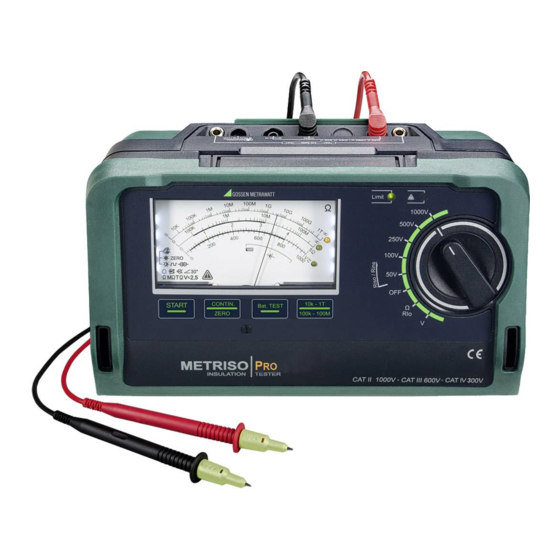
- Page 1 Operating Instructions METRISO 3-349-815-03 Analog Insulation, Low Resistance and Voltage Measurement Instrument 1/9.14 1.888.610.7664 www.calcert.com sales@calcert.com...
- Page 2 Overview of Included Features Scope of Delivery 1 Insulation and resistance measuring instrument METRISO 1 Factory calibration certificate Article number M550R 1 Set of batteries (8 pieces in battery holder) Measurements: 1 Carrying strap U = 50, 100, 250, 500, 1000 V 1 Alligator clip 0.17 ...
- Page 3 Inserting the Battery Holder (side view) Connections (housing top) Battery Compartment Lid 10 M GUARD SHIELD Battery Holder Guard connection see section 5.4 Battery Holder Test Shielded Test Contacts Measuring Connections Resistor Cable Resistor (G500/G10 G500/G1000) Test Probe with Connector with Battery Control Keys Shielded Cable,...
- Page 4 User Interface Red LED: limit value violated Green LED: limit value complied with Refer to page 10 for a description of the LEDs. Red LED: – Interference voltage with device off Display Panel – Blinking indicates standby mode (see description on page 5) –...
- Page 5 Control Panel Keys – Adjusting Screw Analog Display Symbols ➀ a START: Starts insulation resistance measurement depending ➀ on rotary selector switch setting (see measuring ranges ➁ ➅ ➁ ), or low-resistance measurement with automatic polarity ➂ reversal (see low-resistance measuring range ➃...
-
Page 6: Table Of Contents
Contents Page Contents Page Applications ................7 List of Abbreviations and their Meanings ........23 Safety Features and Precautions ..........8 Maintenance ................24 11.1 Battery and Rechargeable Battery Operation ........24 Initial Start-Up ................9 11.2 Fuses .....................24 3.1 Battery Test ..................9 11.2.1Fuse Link – ZERO/FUSE LED ..............24 3.2 Installing or Replacing Batteries .............9 11.2.2Electronic Fuse –... -
Page 7: Applications
Initial start-up Messtechnik GmbH. • Periodic testing The METRISO PRO insulation and resistance measuring instru- ment allows for quick and efficient testing of protective measures • Troubleshooting in electrical systems in accordance with DIN VDE 0100, ÖVE-EN 1 (Austria), SEV 1000 (Switzerland), and regulations specific to other countries as well. -
Page 8: Safety Features And Precautions
Safety Features and Precautions The electronic measuring and test instrument is manufactured Meanings of Symbols on the Instrument and tested in accordance with safety regulations IEC/EN 61010- Warning concerning a point of danger 1/VDE 0411-1 and EN 61557. When used for its intended pur- (attention, observe documentation!) pose, safety of the operator, as well as that of the instrument, is assured. -
Page 9: Initial Start-Up
Initial Start-Up Eight 1.5 V size AA batteries in accordance with IEC LR 6 are required for operation of the insulation measuring instrument. Use new alkaline manganese batteries only. Battery Test Rechargeable NiCd or NiMH batteries may also be used. These A battery test should be conducted after inserting the batteries, or can only be recharged externally. -
Page 10: General Operation
General Operation The test leads are connected to the “+” and “COM” jacks. The instrument can be switched off manually by turning the rotary switch to the OFF position. When measuring electrostatic discharge capacity for floor For purposes of transport and maintenance, we recommend turn- coverings, the shielded cable ing the rotary selector switch to the OFF position in order to avoid should also be connected to... -
Page 11: Analog Display
Testing the LED which Indicates Detection of Interference Voltage Analog Display when Switched Off – OFF Switch Position Insulation Resistance Measuring Ranges Ð Apply a voltage of greater than 50 V (+ and COM jacks). The logarithmic representation of the upper resistance scale Ð... -
Page 12: Insulation Resistance Measurement - Riso/Rins Function
Insulation Resistance Measurement – Riso/Rins Function Attention! Do not touch the instrument’s terminal contacts or the Connection conductive ends of the two test probes during insulation resistance measurement! Note Checking the Measurement Cables If nothing has been connected to the terminal contacts, or if a Before performing insulation measurement, the test resistive load component has been connected for measurement, probes on the measurement cables should be short-cir-... - Page 13 Note If the Limit LED does not light up at all, this means that the selected test voltage value has not been reached. A battery R INS test is advisable in this case (see section 3.1 on page 9). Ð Switching to the Measuring Range with Higher Resolution In order to perform measurement with the enhanced accuracy required for protective measures testing, select the measuring ➀...
-
Page 14: Ending The Measurement - Safe Discharging
Special Case: Capacitive Devices Under Test A guard cable must be used for measurements within a range of 100 G (10 G) 1 T, in order to prevent surface current from distorting measurement results. The guard rings prevent current at the surface of the insulation material from flowing from the Caution! +measurement cable to the –measurement cable, instead of... -
Page 15: Measuring Direct, Alternating And
Measuring Direct, Alternating and The START and CONTIN./ZERO keys have no function in this case. Pulsating Voltage – V Function You can measure direct voltage, as well as sinusoidal alternating volt- age with frequencies ranging from 45 to 65 Hz with this test instrument. Max. -
Page 16: Measuring Low-Resistance Of Up To
Measuring Low-Resistance of up to 5 Measurement Types – R Function You can choose one of two different types of measurement: • Measuring sequence with automatic polarity reversal (reversal According to the regulations, the measurement of low-resistance at of current flow direction) via the START key protective conductors, earth conductors or equipotential bonding •... -
Page 17: Measurement With Automatic Polarity Reversal
Measurement with Automatic Polarity Reversal Measurement with Manual Polarity Reversal Ð Start measurement in both current flow directions by briefly In order to determine whether or not test results are independent pressing the START key, the LED ➃ lights up during measure- of current flow direction, measurement can be performed manu- ment. -
Page 18: Taking Measurement Cables And Extension Cables Into Account (Up To 5 ) - Zero Function (Roffset)
Taking Measurement Cables and Extension Cables into Account (up to 5 ) – ZERO Function (Roffset) Ohmic measurement cable resistance can be subtracted from the 10M measurement results automatically. Proceed as follows: Ð Select function Rlo with the rotary selector switch. Ð... -
Page 19: Technical Data
Technical Data Short- Intrinsic Uncertainty Meas. Scale / Measuring Nominal Range Nominal / Open- Nominal Measuring Overload Circuit Cur- under Reference Qty. Standard Range of Use Circuit Voltage Current I Uncertainty Capacity rent I Conditions 50 V /100 V: 30% of 100 k... - Page 20 Displays Pollution degree Measuring category CAT II 1000 V / CAT III 600 V / CAT IV 300 V Analog display Measuring movement Moving-coil mechanism with core magnet Fuses Scale length 83.13 mm (longest scale) Fuse link FF315mA/1000V, effective in all resistance measuring ranges, 1 additional replace- Limit LED LED lights up red to indicate an exceeded...
- Page 21 Ambient Conditions Mechanical Design Accuracy temp. range 0 ... +40 C Dimensions 225 x 130 x 140 mm Operating temperature –10 ... +50 C Weight Approx. 1.5 kg with batteries Storage temp. range –25 ... +70 C (without batteries) Protection Housing: IP 52, measurement cables and connectors: IP 40 per DIN VDE 0470, Relative humidity...
- Page 22 Display Values in Consideration of Measuring Uncertainty Voltage at Device Under Test During Insulation Resistance Measurement Table for determining minimum display values for insulation resis- tance in consideration of the instrument’s measuring uncertainty: Measuring voltage U at the device under test depending upon its resistance R at nominal voltage U = 50 V, 100 V, 250 V, 500 V...
-
Page 23: List Of Abbreviations And Their Meanings
List of Abbreviations and their Meanings Voltage Test voltage or nominal voltage = 500 V U AC/DC Measured voltage (sinusoidal alternating voltage) Operating voltage Current Nominal current (insulation resistance measurement) /k Test current (low-resistance measurement) Short-circuit current (insulation resistance measure- ment) Resistance 1000... -
Page 24: Maintenance
Maintenance Attention! 11.1 Battery and Rechargeable Battery Operation Disconnect the instrument from the measuring circuit be- When only one filled segment remains in the battery symbol, fore opening the battery compartment lid in order to re- install a new set of batteries or charge the rechargeable batteries. place the fuse (refer to page 5 for location)! Check to make sure that no leakage has occurred at batteries or rechargeable batteries at short, regular intervals, or after the... -
Page 25: 2Electronic Fuse - Zero/Fuse Led
Replacing the Fuse 11.3 Housing Ð Open the battery compartment lid by loosening the two No special maintenance is required for the housing. Keep outside surfaces clean. Use a slightly dampened cloth or a plastic cleaner screws. for cleaning. Avoid the use of cleansers, abrasives or solvents. Ð... -
Page 26: Recalibration
Recalibration Appendix The measuring tasks performed with your instrument, and the 13.1 Sample Connection Layouts for Insulation Resistance stressing it’s subjected to, influence aging of its components and Measurement may result in deviation from the specified levels of accuracy. Insulation Resistance Measurement per DIN VDE 0100, Part 600 In the case of strict measuring accuracy requirements, as well as Between each active conductor and ground in the event of use at construction sites with frequent stress due... - Page 27 Insulation Resistance Measurement in Different Types of Systems Between each active conductor (phase and neutral TN–S conductors) and ground • With or without consumer • N – PE, separately Between each active conductor and the PEN conductor TN–C • With or without consumer •...
- Page 28 • With or without consumer Caution: – Open the overcurrent protective device. – Disconnect the N conductor. – Jumper the L and N conductors. – Insulation measurement between L conductors and N to 3-phase current (switched at all poles) In the distributor: individual and combined measurements GMC-I Messtechnik GmbH 1.888.610.7664 www.calcert.com...
-
Page 29: Attaching The Test Probe Holder To The Carrying Strap
13.2 Attaching the Test Probe Holder to the Carrying Strap Slide the strap through the test probe holder. Detach the strap from the instrument: Turn out the slotted screw (M3) at the bottom. Front View Side View Strap Clasp Bottom Left Bottom Right Clasp Eyelet for Attachment to Tester... -
Page 30: Technical Data For Measurement Cables (Scope Of Delivery: Ks17-4 Safety Cable Set)
13.3 Technical Data for Measurement Cables (scope of delivery: KS17-4 safety cable set) Feed the strap through from the front of the test instrument and secure it Electrical Safety with the slotted screw (M3). Maximum rated voltage 600 V 1000 V 1000 V Measuring category CAT IV... -
Page 31: Optional Accessories (Not Included)
13.4 Optional Accessories (not included) ISO Calibrator 1 (material no. M662A) Calibration adapter for testing the accuracy of instru- ments used for measuring insulation resistance and low-resistance for test voltages of up to 1000 V (per VDE 0413, parts 1, 2, 4 and 10). KS-C (material no.
Need help?
Do you have a question about the METRISO PRO and is the answer not in the manual?
Questions and answers