Sign In
Upload
Manuals
Brands
Gossen MetraWatt Manuals
Measuring Instruments
mavolog pro
Gossen MetraWatt mavolog pro Manuals
Manuals and User Guides for Gossen MetraWatt mavolog pro. We have
2
Gossen MetraWatt mavolog pro manuals available for free PDF download: Operating Instructions Manual
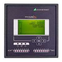
Gossen MetraWatt mavolog pro Operating Instructions Manual (206 pages)
power quality analyzer
Brand:
Gossen MetraWatt
| Category:
Measuring Instruments
| Size: 17 MB
Table of Contents
Table of Contents
4
Power Quality Analyzer Mavolog Pro
10
Warnings, Information and Notes Regarding Designation of Product
11
Before Switching the Device on
12
Device Switch off Warning
12
Health and Safety
13
Real Time Clock
13
Disposal
14
Opening of Equipment / Repair
14
Basic Description and Operation
15
Contents
15
Description of the MAVOLOG PRO Power Quality Analyzer
16
Abbreviation/Glossary
17
Purpose and Use of the MAVOLOG PRO Power Quality Analyzer
19
Device Application and Benefits
20
Main Features, Supported Options and Functionality of MAVOLOG PRO Power Quality Analyzer
21
Connection
26
Mounting
27
Electrical Connection for MAVOLOG PRO Power Quality Analyzer
28
Connection of Input/Output Modules
30
Communication Connection
33
Connection of Real Time Synchronization Module C
33
Connection of Aux. Power Supply
35
First Steps
36
Installation Wizard
36
Notification Icons
38
LCD Navigation
39
Settings
40
MAVO-View Software
40
Devices Management
41
Device Settings
43
Real Time Measurements
44
Data Analysis
46
My Devices
46
Upgrade
46
Software Upgrading
47
Setting Procedure
49
General Settings
50
Description & Location
50
Average Interval
50
Language
50
Currency
50
Temperature Unit
50
Date Format
51
Date and Time
51
Real Time Synchronization Source
51
Time Zone
51
Auto Summer/Winter Time
51
Maximum Demand Calculation (MD Mode)
52
Thermal Function
52
Fixed Window
52
Sliding Windows
53
MD Time Constant (Min)
54
Maximum Demand Reset Mode
55
Min/Max Reset Mode
55
Starting Current for PF and PA (Ma)
55
Starting Current for All Powers (Ma)
55
Starting Voltage for SYNC
55
Harmonics Calculation
55
Reactive Power & Energy Calculation
55
LCD Navigation
56
Connection
57
Connection Mode
57
Setting of Current and Voltage Ratios
57
Neutral Line Primary/Secondary Current (A)
57
Used Voltage/Current Range (V/A)
57
Frequency Nominal Value (Hz)
57
Max. Demand Current for TDD (A)
57
Wrong Connection Warning
57
Energy Flow Direction
58
CT Connection
58
LCD Navigation
58
Communication
59
Push Data Format
59
Push Response Time (Sec)
59
(Push) Time Synchronization
59
USB Communication
59
Ethernet Communication
59
Device Address
60
IP Address
60
IP Hostname
60
Local Port
60
Subnet Mask
61
Gateway Address
61
NTP Server
61
Push Communication Settings
61
MAC Address
62
Firmware Version
62
Communication Modes
62
LCD Navigation
64
Display
65
Contrast/Black Light Intensity
65
Saving Mode (Min)
65
Demo Cycling Period (Sec)
65
Custom Screen 1/2/3
65
LCD Navigation
66
Security
66
Password - Level 0 >PL0)
66
Password - Level 1 >PL1)
66
Password - Level 2 >PL2)
66
A Backup Password->BP)
66
Password Locks Time >Min)
67
Password Setting
67
Password Modification
67
Password Disabling
67
Password and Language
67
LCD Navigation
67
Energy
68
Active Tariff
68
Common Energy Counter Resolution
68
Common Energy Cost Exponent
68
Counter Divider
68
Common Tariff Price Exponent
68
Kwh Price in Tariff (1,2,3,4)
69
Kvarh Price in Tariff (1,2,3,4)
69
Kvah Price in Tariff (1,2,3,4)
69
LED Energy Counter
69
LED Number of Pulses
69
LED Pulse Length (Ms)
69
Measured Energy
69
Individual Counter Resolution
69
Tariff Selector
69
Tariff Clock
70
Holidays/Holiday Date 1-20
71
LCD Navigation
71
Inputs and Outputs
72
Introduction
72
I/O Modules Options
72
I/O Modules
72
Analogue Output Module
72
Analogue Input Module
73
Pulse Output Module
74
Digital Input Module
74
Pulse Input Module
74
Tariff Input Module
74
Bistable Alarm Output Module
74
Alarm Output
75
Status (Watchdog) and Relay Output Module
75
Auxiliary I/O Modules a & B
75
RTC Synchronization Module C
76
LCD Navigation
77
Alarms
78
Alarms PUSH Functionality
78
Push Data to Link
78
Pushing Period
78
Pushing Time Delay
79
Alarms Group Settings
79
Alarm Statistics Reset
79
MD Time Constant (Min)
79
Compare Time Delay (Sec)
79
Hysteresis (%)
79
Response Time
80
Individual Alarm Settings
80
Advanced Recorders
81
Logical Inputs and Logical Functions
82
Triggers
83
Recorders
102
Conformity of Voltage with en 50160 Standard
113
General PQ Settings
113
Monitoring Mode
113
Electro Energetic System
113
Monitoring Voltage Connection
114
Nominal Supply Voltage
114
Nominal Power Frequency
114
Flicker Calculation Function
114
Monitoring Period (Weeks)
114
Monitoring Start Day
114
Flagged Events Setting
114
Sending Reports and Report Details
115
EN 50160 Parameters Settings
116
Reset
117
Reset Energy Counter
117
Reset Energy Counter Cost
117
Reset MD Values
117
Reset Last Period MD
117
Synchronize MD
117
Alarm Relay [1/2/3/4] off
118
Reset Min/Max Values
118
Reset Alarm Statistic
118
LCD Navigation
118
Measurements
119
Online Measurements
119
Interactive Instrument
120
Supported Measurements
121
Available Connections
121
Selection of Available Quantities
121
Explanation of Basic Concepts
126
Sample Factor M V
126
Average Interval MP
126
Sample Frequency
126
Average Interval
126
Average Interval for Measurements and Display
126
Average Interval for Min/Max Values
126
Average (Storage) Interval for Recorders
126
Average (Aggregation) Interval for PQ Parameters
126
Power and Energy Flow
127
Calculation and Display of Measurements
128
Keyboard and LCD Display Presentation
128
Measurements Menu Organization
129
Measurements Menu MAVOLOG PRO
129
Present Values
130
Present Values on LCD and TFT Display
130
Voltage
130
Current
131
Active, Reactive and Apparent Power
131
Power Factor and Power Angle
131
Frequency
132
Energy Counters
132
MD Values
132
Harmonic Distortion
132
Harmonic Distortion Parameters
133
Flickers Evaluation
133
Flickers
133
Customized Screens
133
Min/Max Values
134
Average Interval for Min/Max Values
134
Display of Min/Max Values on MAVOLOG PRO
134
Display of Min/Max Values - MAVO-View Software
135
Alarms
136
Survey of Alarms
137
Demo Cycling
138
Harmonic Analysis
138
Display of Harmonic Parameters
139
Harmonic Analasis - MAVO-View
140
PQ Analysis
143
LCD Navigation
151
PQDIF and COMTRADE Files on MAVOLOG PRO - Concept Description
152
Working with PQDIF and COMTRADE Files on the Device
152
Accessing PQDIF Files
152
Accessing COMTRADE Files
158
Pqdiffractor - PQDIF and COMTRADE File Viewer
159
Technical Data
162
Accuracy
162
Measurement Inputs
164
Connection
165
Communication
165
Input/Output Modules
166
Safety
169
Time Synchronization Input
169
Universal Power Supply
170
Mechanical
170
Ambient Conditions
170
Real Time Clock
171
Operating Conditions
171
Dimensions
172
Appendices
174
APPENDIX A: MODBUS Communication Protocol
174
APPENDIX B: DNP3 Communication Protocol
183
APPENDIX C: Equations
191
APPENDIX D: XML Data Format
195
APPENDIX E: PQDIF and COMTRADE Recorder Data Storage Organization
197
APPENDIX F: IEC61850 Protocol Support Overview
200
Advertisement
Gossen MetraWatt mavolog pro Operating Instructions Manual (18 pages)
Power Quality Analyzer
Brand:
Gossen MetraWatt
| Category:
Measuring Instruments
| Size: 0 MB
Table of Contents
1 Features
2
2 Description
2
Table of Contents
2
3 Application and Benefits
3
4 Compliance with Standards
3
PQ Reports
4
5 Voltage Quality
4
PQ Recording Settings
4
Interactive Instrument
5
6 Measurements
5
Online Measurements
5
Selection of Available Quantities
5
7 Recorder
8
8 Alarms
8
Memory Card
8
9 Real Time Synchronisation
9
Basic Accuracy under Reference Conditions
10
INPUT / OUTPUT Modules
10
Measurement Inputs
10
10 Communication
9
GPS Time Synchronization
9
IRIG Time Code B (IRIG-B)
9
Network Time Protocol (NTP)
9
11 Technical Data
10
Ambient Conditions
11
Mechanical
11
Safety
11
Time Synchronisation Input
11
Universal Power Supply
11
11.10 Connection Cables
12
MAVO-View - Setting and Acquisition Software
12
Real Time Clock
12
12 Connection
13
13 Dimensional Drawing
15
14 Connection Table
15
15 Data for Ordering
16
General Ordering Code
16
Abbreviations
17
Example of Ordering
17
16 Repair and Replacement Parts Service
17
17 Product Support
17
Advertisement
Related Products
Gossen MetraWatt MAVOLUX COMPACT
Gossen MetraWatt MAVOSPEC BASE
Gossen MetraWatt MAVO-SPOT
Gossen MetraWatt MAVO-MONITOR
Gossen MetraWatt MAVO-SPOT 2
Gossen MetraWatt MAVOPAD
Gossen MetraWatt MAVOMASTER
Gossen MetraWatt MAVOPROBE
Gossen MetraWatt MAVOPROBE UVA
Gossen MetraWatt M504G
Gossen MetraWatt Categories
Measuring Instruments
Test Equipment
Multimeter
Adapter
Controller
More Gossen MetraWatt Manuals
Login
Sign In
OR
Sign in with Facebook
Sign in with Google
Upload manual
Upload from disk
Upload from URL