Table of Contents
Advertisement
Quick Links
Advertisement
Table of Contents

Related Manuals for Trumpf TruTool N 700


Summary of Contents for Trumpf TruTool N 700
- Page 1 Operator's manual TruTool N 700 (1A1) Distributed By: english...
-
Page 2: Table Of Contents
Selecting a die Selecting a punch Setting the penetration depth Selecting and attaching a handle Rotating the motor handle Operation Working with the TruTool N 700 Changing the cutting direction Nibbling with templates Making interior cutouts Maintenance Replacing the tool... - Page 3 Appendix: Guarantee, declaration of con- formity, replacement parts lists E528EN_06 2011-04 Table of contents...
-
Page 4: Safety
Connect the fault current (FI) circuit breaker with a maximum breaking current of 30 mA when using the electric tool out- side. Ø Only use original TRUMPF accessories. Damage to the machine due to improper handling. WARNING Ø Wear safety glasses, hearing protection, protective gloves and work shoes when working at the machine. - Page 5 Risk of injury to hands. WARNING Ø Do not reach into the processing line with your hands. Ø Use both hands to hold the machine. Risk of injury from hot and sharp chips. WARNING Chips exit the chip ejector at high speed. Ø...
-
Page 6: Description
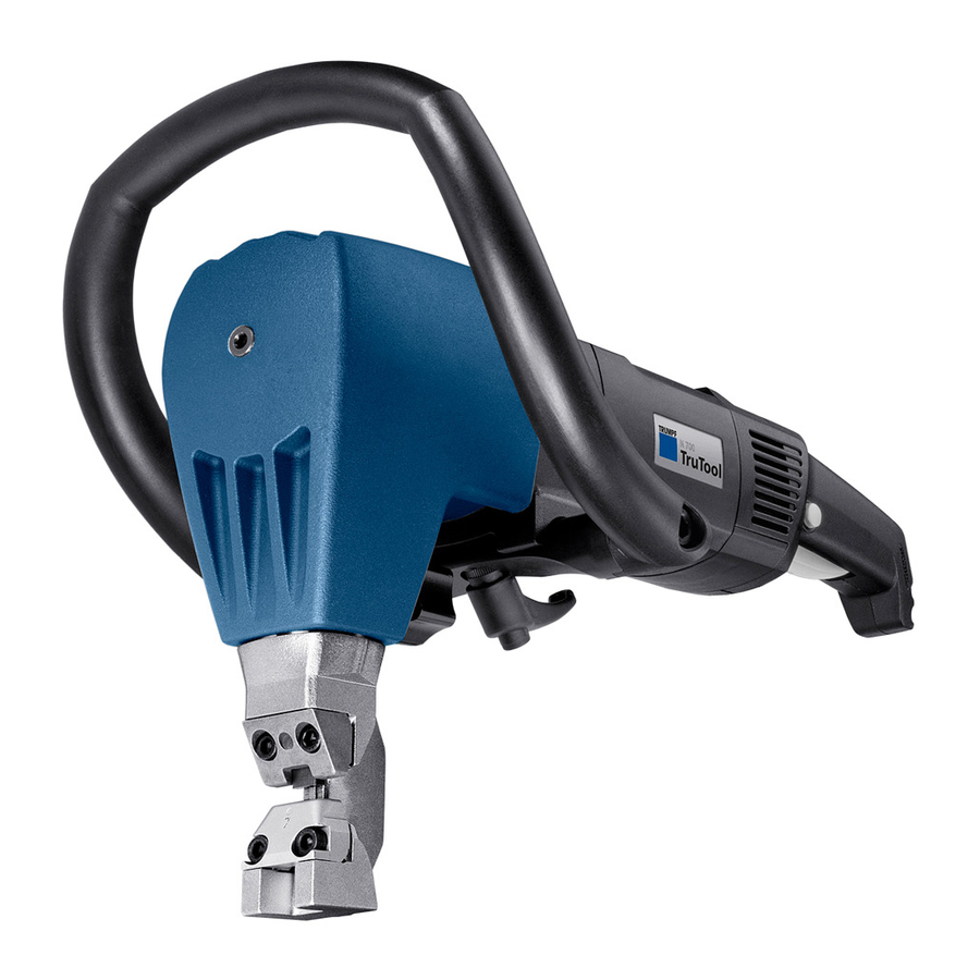
Chip ejector Nibbler TruTool N 700 Fig. 38379 Intended use The TRUMPF Nibbler TruTool N 700 is an electrically operated hand-held device for: ■ Cutting of plate-shaped workpieces made of a punchable material such as steel, aluminum, nonferrous heavy metal and plastic. -
Page 7: Technical Data
Note The nibbling process produces cutting edges free of deforma- tions. Technical data Other countries Voltage 230 V 120 V 110 V 120 V Frequency 50/60 Hz 50/60 Hz 50 Hz 50/60 Hz Max. material thickness: 7.0 mm 7.0 mm 7.0 mm 0.28 in Steel 400 N/mm... -
Page 8: Noise And Vibration Information
Symbol Name Meaning Read operating manual Read the operator's manual and safety information in their entirety before starting up the machine. Closely follow the instructions given. Safety class II Indicates a doubly insulated tool. Alternating current Type or property of current Volt Voltage Ampere... - Page 9 ■ The specified vibration emission value can also be applied for a provisional estimate of the vibration load. ■ Times during which either the machine is switched off or run- ning but not actually in use can considerably reduce the vibration load during the entire working period.
-
Page 10: Setting Work
Setting work Selecting a die Vigorous upward and downward movements (hammering) CAUTION due to unsuitable die. Excessive tool wear and increasing loads on the machine. Ø Use dies with the greatest height possible (keep distance X, shown in the drawing below, as small as possible). Die (see following table) Workpiece Punch guide... -
Page 11: Selecting A Punch
Material Type of die Type of die Type of die Mild steel >5-7 400 N/mm Stainless steel 600 N/mm Stainless steel -2.5 800 N/mm Material thickness in mm for profiles with press brake bending up to 90° Aluminum >3-5 >5-7 250 N/mm Mild steel >3-5... -
Page 12: Setting The Penetration Depth
Setting the penetration depth Note A greater penetration depth causes less vibrations, but a greater effort is required when pushing the machine forward and the service life of the punch is reduced. Eccentric shaft Locking mechanism Die carrier Penetration depth Punch Fig. -
Page 13: Selecting And Attaching A Handle
Compact handle Clamping lever Motor handle Compact handle TruTool N 700 Fig. 54786 The compact handle is developed for application in situations where space is limited (e.g. profile machining). Moreover it is made out of steel and is heat resistant. -
Page 14: Rotating The Motor Handle
Swiveling the handle Note Each handle can be clamped in 2 positions using indexing. 2. Rotate the clamping lever (3) approx. 2 full turns. 3. Swivel the handle. 4. Fix the clamping lever (3) in place. Rotating the motor handle Damage to property due to dust being drawn into the CAUTION ventilation slots... -
Page 15: Operation
Operation Working with the TruTool N 700 Damage to the machine due to improper handling. WARNING Ø Make sure the machine is always in a stable position when operating it. Ø Never touch the tool while the machine is running. -
Page 16: Changing The Cutting Direction
− Hold down the release inhibiter knob (1) and press the on/off switch (2). − Release the on/off switch (2). The switch remains engaged. The motor is running. Ø To switch the machine to instantaneous connection: − Hold down the release inhibiter knob (1) and press the on/off switch (2). -
Page 17: Making Interior Cutouts
Making interior cutouts Ø Make a start hole at least 60 mm in diameter. E528EN_06 2011-04 Nibbling with templates... -
Page 18: Maintenance
Maintenance Electrical voltage! Risk of fatal injury due to electric shock. DANGER Ø Remove the plug from the plug socket before undertaking any maintenance work on the machine. Risk of injury due to incorrect repair work WARNING Machine does not work properly. Ø... -
Page 19: Changing The Punch
3. Pull die carrier (3) out towards the bottom. 4. Screw out the punch (2). Note Use lubricating grease "G1" for lubrication (TRUMPF order no. 139440). 5. Lightly lubricate the square part of the punch and the die car- rier bore hole. -
Page 20: Changing The Die And Punch Guide
1. Unscrew and remove the screws (6). 2. Clean the support areas on the die carrier (3). 3. Clean the replacement parts if necessary. Note Use lubricating grease "G1" for lubrication (TRUMPF order no. 139440). 4. Lubricate the guide surfaces of the punch guide. Note Use original screws only. -
Page 21: Changing The Wearing Plate
Fig. 9432 1. Regrind the grinding surface in accordance with the diagram, making sure that it is well-cooled during the process. 2. Lightly apply fine-grained oil stone to the cutting edge. Changing the wearing plate The wearing plate protects the die carrier against excessive wear. -
Page 22: Changing The Power Cable
If the power cable is to be replaced, it should be procured from the manufacturer or an authorized dealer to avoid safety haz- ards. Note For TRUMPF service addresses, see www.trumpf-power- tools.com. Replacing carbon brushes The motor comes to a standstill whenever the carbon brushes are worn out. -
Page 23: Original Accessories, Wearing Parts And
Original accessories, wearing parts and optional items Supplied Wearing part Optional Order no. original accessories Punch (standard) 0104589 Punch for high-tensile sheets 0104590 Die 5 0098723 Die 7 0098722 Die P7 0098721 Wearing plate 0119173 Bow-handle, complete 1279590 Compact handle, complete 1279618 Case 1279611... -
Page 24: E528En_06
Note For TRUMPF service addresses, see www.trumpf-powertools.com. 4. Send the order to the TRUMPF representative office. Original accessories, wearing parts and optional 2011-04 E528EN_06 items... - Page 25 Appendix: Guarantee, declaration of conformity, replacement parts lists E528EN_06 2011-04 Appendix: Guarantee, declaration of conformity, replacement parts lists...
- Page 26 Appendix: Guarantee, declaration of conformity, 2011-04 E528EN_06 replacement parts lists...
Need help?
Do you have a question about the TruTool N 700 and is the answer not in the manual?
Questions and answers