Table of Contents
Advertisement
Advertisement
Table of Contents

Subscribe to Our Youtube Channel
Related Manuals for Trumpf TruTool N 1000


Summary of Contents for Trumpf TruTool N 1000
- Page 1 Operator's manual TruTool N 1000 (1B1)
-
Page 2: Table Of Contents
Noise and vibration information Setting work Selecting a die Select punch Select gear Setting the penetration depth Operation Working with TruTool N 1000 Changing the cutting direction Nibbling with templates Producing interior cutouts Maintenance Replacing the tool Changing the punch... -
Page 3: Safety
30 mA when using the electric tool out- side. Ø Protect the machine cable in areas where there are sparks. Ø Only use original TRUMPF accessories. Damage to the machine due to improper handling. WARNING Ø Wear safety glasses, hearing protection, protective gloves and working shoes when working. - Page 4 Risk of injury to hands. WARNING Ø Do not reach into the processing line with your hands. Ø Use both hands to hold the machine. Risk of injury from hot and sharp chips! WARNING Chips exit the chip ejector at high speed. Use a chip bag.
-
Page 5: Description
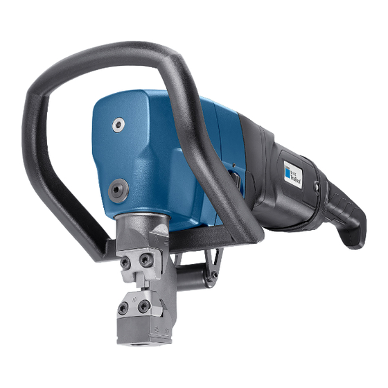
Suspension bracket (optional) Nibbler TruTool N 1000 Fig. 54784 Intended use The TRUMPF Nibbler TruTool N 1000 is an electrically operated hand-held device for: ■ Cutting of plate-shaped workpieces made of a punchable material such as steel, aluminum, nonferrous heavy metal and plastic. -
Page 6: Technical Data
Technical data TruTool N 1000 Other countries Voltage 230 V 120 V 110 V 120 V Frequency 50/60 Hz 50/60 Hz 50 Hz 50/60 Hz Permissible material thickness: 10 mm 10 mm 10 mm 0.394 in (1st gear) (1st gear) -
Page 7: Symbols
Symbols Note The following symbols are important for reading and understand- ing the instruction manual. The correct interpretation of the sym- bols will help you operate the machine better and safer. Symbol Name Meaning Read operating manual Read the operator's manual and safety information in their entirety before starting up the machine. - Page 8 Vigorous upward and downward movements (hammering) CAUTION due to unsuitable die. Excessive tool wear and increasing loads on the machine. Ø Use dies with the greatest height possible (keep distance X, shown in the drawing below, as small as possible). Notes The specified vibration emission value was measured in ■...
-
Page 9: Setting Work
Setting work Selecting a die Vigorous upward and downward movements (hammering) CAUTION due to unsuitable die. Excessive tool wear and increasing loads on the machine. Ø Use dies with the greatest height possible (keep distance X, shown in the drawing below, as small as possible). Die (see following table) Workpiece Punch guide... -
Page 10: Select Punch
Types of die and their respective order numbers Fig. 18270 Type of die Type of die Type of die Type of die Material thickness in mm for a flat single rolled sheet >5-7 >7-10 >10-12 Aluminum 250 N/mm >5-7 >7-10 Mild steel 400 N/mm >5-7 Stainless steel 600 N/mm... -
Page 11: Select Gear
Components Standard punch Punch for high-ten- sile steels Area of application Suitable for machining Suitable for machining materials up to 400 N/ materials over 400 N/ e. g. aluminum, e. g. stainless mild steel. steel. Order number 112900 120344 Aluminum 250 N/mm Mild steel 400 N/mm Stainless steel 600 N/ Stainless steel 800 N/... -
Page 12: Setting The Penetration Depth
Die carrier 40 Gear switch Punch 46 Roller holder Suspension bracket (optional) Nibbler TruTool N 1000 Fig. 54784 1. Put the machine into a stable position. 2. Switch on the machine briefly: − Press the release switch (3). −... - Page 13 Die carrier 14 Clamping screw Punch 22 Eccentric shaft Fig. 9763 1. Rotate the eccentric shaft (22) until the punch (9) has reached its maximum penetration depth. 2. Open the locking mechanism. Note One rotation of 360° corresponds to a height adjustment of 1.75 mm.
-
Page 14: Operation
Operation Damage to the machine due to improper handling. WARNING Ø Make sure the machine is always in a stable position when operating it. Ø Never touch the tool while the machine is running. Ø Always operate the machine away from your body. Ø... -
Page 15: Working With Trutool N 1000
Working with TruTool N 1000 On switch Release switch Off switch Fig. 9306 Positioning the machine 1. Put the machine in position in front of the tool. Switching on Either Ø To switch the machine to continuous operation: − Keep the release switch (3) pressed. -
Page 16: Nibbling With Templates
2. Rotate the die carrier (7) in the desired direction. 3. Retighten the clamping screw (14) by hand. 4. Check the penetration depth of the punch. Nibbling with templates The following requirements must be met when nibbling with tem- plates: ■... -
Page 17: Maintenance
Maintenance Electrical voltage! Risk of fatal injury due to electric shock. DANGER Ø Remove the plug from the plug socket before undertaking any maintenance work on the machine. Risk of injury due to incorrect repair work WARNING Machine does not work properly. Ø... -
Page 18: Changing The Punch
Punch Screws for fastening the die 14 Clamping screw and punch guide Tube of lubricating grease "S1" Wearing plate Die holder Fig. 9764 Changing the punch 1. Loosen the clamping screw (14). 2. Rotate the die holder (7) by 45°. 3. -
Page 19: Changing The Die And Punch Guide
Notes ■ Dies cannot be reground. ■ Use only original spare parts from TRUMPF. ■ The punch can be reground in total 5 to 10 mm, depending on with which die it is used. Shorter punches must be replaced (risk of collision). - Page 20 Type of die Minimum length X Regrinding reserve for punch 85 mm 12 mm Tab. 8 Minimum length Fig. 9017 1. Regrind the grinding surface according to the sketch, paying attention to good cooling. 2. Dress the cutting edge lightly with a fine oil stone. Replacing the tool E232en_06...
-
Page 21: Changing The Wearing Plate
Changing the wearing plate The wearing plate protects the die carrier against excessive wear. Note Excessive wearing can overload the machine and lead to a wor- sening of the cutting quality. Raised part Depression Fig. 9762 The wearing plate must be replaced when: ■... -
Page 22: Changing The Power Cable
If the power cable is to be replaced, it should be procured from the manufacturer or an authorized dealer to avoid safety haz- ards. Note For TRUMPF service addresses, see www.trumpf-power- tools.com. Replacing carbon brushes The motor comes to a standstill whenever the carbon brushes are worn out. -
Page 23: Accessories And Consumables
Accessories and consumables Name Order number Scope of deliv- Standard punch 0112900 Punch for high-strength sheets 0120344 Die for up to 5 mm (type 5) 0130651 Die for 5-7 mm (type 7) 0112899 Die for 7-10 mm (type 10) 0112898 Die for profile sheet of 7-10 mm (type P10) 0112897 Wearing plate... - Page 24 − Correct address. − Desired delivery type (e.g. air mail, courier, express mail, ordinary freight, parcel post). Note For TRUMPF service addresses, see www.trumpf‑powertools.com. 4. Send the order to the TRUMPF representative office. Accessories and consumables E232en_06...
-
Page 25: Appendix: Declaration Of Conformity, Guarantee, Replacement Parts Lists
Appendix: Declaration of conformity, guarantee, replacement parts lists E232en_06 Appendix: Declaration of conformity, guarantee, replacement parts lists... - Page 26 Appendix: Declaration of conformity, guarantee, E232en_06 replacement parts lists...
Need help?
Do you have a question about the TruTool N 1000 and is the answer not in the manual?
Questions and answers