Table of Contents
Advertisement
Quick Links
Advertisement
Table of Contents

Related Manuals for IFM Electronic LR7300


Summary of Contents for IFM Electronic LR7300
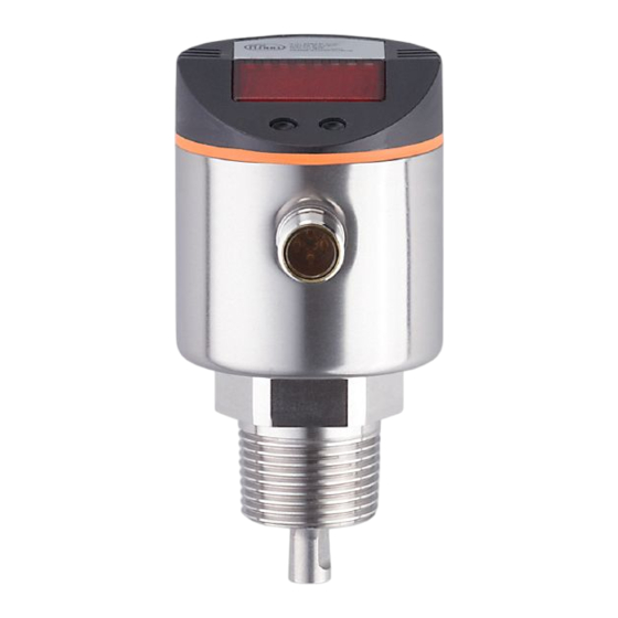
- Page 1 Operating instructions Electronic level sensor LR7300...
-
Page 2: Table Of Contents
Contents 1 Preliminary note ���������������������������������������������������������������������������������������������������4 1�1 Symbols used ������������������������������������������������������������������������������������������������4 2 Safety instructions �����������������������������������������������������������������������������������������������4 3 Items supplied������������������������������������������������������������������������������������������������������5 4 Functions and features ����������������������������������������������������������������������������������������5 4�1 Applications ���������������������������������������������������������������������������������������������������6 4�1�1 Restriction of the application area ��������������������������������������������������������6 5 Function ���������������������������������������������������������������������������������������������������������������7 5�1 Measuring principle ���������������������������������������������������������������������������������������7 5�2 Features of the unit ����������������������������������������������������������������������������������������8 5�2�1 Easy set-up �������������������������������������������������������������������������������������������8 5�2�2 Display functions ����������������������������������������������������������������������������������8 5�2�3 Switching functions �������������������������������������������������������������������������������8... - Page 3 10�1 Parameter setting in general ���������������������������������������������������������������������23 10�2 Entering the probe length (unit on delivery) �����������������������������������������������25 10�3 Configuration of the display �����������������������������������������������������������������������25 10�4 Offset setting ����������������������������������������������������������������������������������������������25 10�5 Setting of output signals ����������������������������������������������������������������������������26 10�5�1 Setting of the output function ������������������������������������������������������������26 10�5�2 Set the switching limits (hysteresis function) ������������������������������������26 10�5�3 Set the switching limits (window function) ����������������������������������������26 10�5�4 Setting of the switch-off delay �����������������������������������������������������������26 10�5�5 Response of the outputs in case of a fault ���������������������������������������26...
-
Page 4: Preliminary Note
1 Preliminary note 1.1 Symbols used ► Instructions > Reaction, result […] Designation of keys, buttons or indications → Cross-reference Important note Non-compliance may result in malfunction or interference� Information Supplementary note� 2 Safety instructions • Please read this document prior to set-up of the unit� Ensure that the product is suitable for your application without any restrictions�... -
Page 5: Items Supplied
Order number 73 - 90 / ¾" NPT E43206 Only use rods from ifm electronic gmbh� The optimum function is not ensured when using components from other manufacturers� 4 Functions and features The unit continuously detects the level in tanks and generates output signals according to the parameter settings�... -
Page 6: 4�1 Applications
For correct function the unit needs a large enough metal launching plate� It is necessary for transferring the microwave pulse to the tank with optimum transmission power� The flange plates that are available as accessories are not sufficient as launching plates (for suitable launching plates → 6.4). For installation in closed metal tanks, the tank lid serves as a launching plate�... -
Page 7: Function
• The unit is not suitable for applications where the probe is subjected to permanent and high mechanical stress (e�g� strongly moving viscous media or strongly flowing media)� • Use preferably in metal tanks� When installed in plastic tanks, deterioration caused by electromagnetic interference may occur (noise immunity according to EN61000-6-2)�... -
Page 8: 5�2 Features Of The Unit
5.2 Features of the unit 5.2.1 Easy set-up • When operating voltage is applied to the unit for the first time, the probe length must be entered. Then the unit is ready for operation (→ 10.2). • If necessary, parameters for the output signals and optimisation of the monitoring functions can be set (→... -
Page 9: 5�2�4 Offset For Indicating The Real Level In The Tank
Fig. 5-3 Fig. 5-4 L = level; HY = hysteresis; FE = window • For each switching output a switch-off delay of max� 60 s can be set (e�g� for especially long pump cycles)� 5.2.4 Offset for indicating the real level in the tank The zone between tank bottom and lower edge of the probe can be entered as offset value [OFS]�... -
Page 10: 5�3 Io-Link
If, however, it is not received again in sufficient strength within the delay time, the outputs pass into the safe state� In case of heavy foam formation and turbulence, note the examples of how to create a steady area (→ 6.1). 5.3 IO-Link General information This unit has an IO-Link communication interface which requires an IO-Link-... -
Page 11: Installation
6 Installation 6.1 Installation location / environment • Vertical installation from the top is preferred� • For a safe function, the unit requires a launching plate (→ 6.4). • For optimum operation the unit is to be installed as near as possible to the tank wall�... - Page 12 • For installation in pipes: - The inside pipe diameter (d) must be at least 100 mm (fig� 6-1)� - Only install the unit in metal pipes� • For installation in connection pieces: - The diameter of the boss (d) must be at least 60 mm (fig� 6-2)� - The height of the boss (h) must not exceed 40 mm (fig�...
- Page 13 Fig. 6-3 Fig. 6-4 50mm To avoid incorrect measurements in case of heavy foam formation and turbulence: ► If possible, install the sensor in a steady area� Example how to create a steady area: - Installation in bypass or still pipe (see fig� 6-5) - Separation of the installation location by metal sheets / perforated sheets (without figure) Min�...
-
Page 14: 6�2 Installation Of The Probe
Fig. 6-5 6.2 Installation of the probe The rod is not included in the scope of supply. It has to be ordered separately (→ 3 Items supplied)� Fixing of the rod: ► Screw the rod to the unit and tighten it� Recommended tightening torque: 4 Nm�... -
Page 15: 6�3 Shortening Of The Probe
6.3 Shortening of the probe The rod can be shortened to adapt the probe to different tank heights� Ensure that the probe length is never below the minimum permissible probe length of 10 cm (L )! The unit does not support probe lengths below 10 cm�... -
Page 16: 6�4�1 Installation In Closed Metal Tanks (Without Flange Plate)
6.4.1 Installation in closed metal tanks (without flange plate) Fig. 6-6 Fig. 6-7 ► The lower edge of the process connection should be flush with the installation environment (fig� 6-6)� ► Avoid non-flush installation (fig� 6-7)� The height can be slightly corrected by means of appropriate sealing material (e�g�... -
Page 17: 6�4�3 Installation In Open Tanks
► Install the flange plate with the flat surface showing to the tank and fix it with appropriate screws� A seal (A in fig� 6-9) can be inserted between flange plate and tank� Some flange plates are supplied with a seal� ►... -
Page 18: 6�4�4 Installation In Plastic Tanks
6.4.4 Installation in plastic tanks 150 mm To enable sufficient transfer of the measured signal, note in case of installation in plastic tanks or metal tanks with plastic lid: ► a drill hole with a minimum diameter of 150 mm must be applied to the plastic lid�... -
Page 19: Electrical Connection
7 Electrical connection The unit must be connected by a qualified electrician� The national and international regulations for the installation of electrical equipment must be adhered to� Voltage supply according to EN 50178, SELV, PELV� ► Disconnect power� ► Connect the unit as follows: OUT2 OUT1/IO-Link Connection... -
Page 20: Operating And Display Elements
8 Operating and display elements 3 4 5 6 Mode/Enter 1 to 8: Indicator LEDs - LED 1: green = indication of the level in cm - LED 2: green = indication of the level in inch� - LED 3: green = indication of the level in % of the final value of the measuring range� - LED 4 - LED 6: not used�... -
Page 21: Menu
9 Menu 9.1 Menu structure cm inch S... -
Page 22: 9�2 Explanation Of The Menu
9.2 Explanation of the menu SP1/rP1 Upper / lower limit value for the level at which OUT1 switches� FH1/FL1 Upper / lower limit for the acceptable range (monitored by OUT1)� SP2/rP2 Upper / lower limit value for the level at which OUT2 switches� FH2/FL2 Upper / lower limit for the acceptable range (monitored by OUT2)�... -
Page 23: Parameter Setting
10 Parameter setting During parameter setting the unit remains in the operating mode internally� It continues to monitor with the existing parameters until the parameter setting has been completed� 10.1 Parameter setting in general 3 steps must be taken for each parameter setting: Select parameter ►... - Page 24 • Change from menu level 1 to menu level 2: ► Press [Mode/Enter] until [EF] is displayed. Mode/Enter Set ► Briefly press [Set]� > The first parameter of the submenu is Mode/Enter Set displayed (here: [res])� • Locking / unlocking The unit can be locked electronically to prevent unintentional settings: ►...
-
Page 25: 10�2 Entering The Probe Length (Unit On Delivery)
10.2 Entering the probe length (unit on delivery) On delivery of the unit, you must first enter the probe length� The complete parameter setting menu cannot be accessed before this� Malfunctions may occur if the wrong probe length is set� ►... -
Page 26: 10�5 Setting Of Output Signals
10.5 Setting of output signals 10.5.1 Setting of the output function ► Select [OU1] / [OU2] and set the switching function: [Hno] = hysteresis function/NO, [Hnc] = hysteresis function/NC, [Fno] = window function/NO, [Fnc] = window function/NC� Note: If the upper switch point is used as an overflow protection, the setting OUx = Hnc (NC function) is recommended�... -
Page 27: 10�5�6 Setting Of The Delay Time After Signal Loss
10.5.6 Setting of the delay time after signal loss ► Select [dFo] and set a value between 0�2 and 5�0 s� At 0�0 (= factory setting) the delay time is not active� Mind the dynamics of your application� In case of fast level changes it is recommended to adapt the value step by step�... -
Page 28: Operation
11 Operation After power on, the unit is in the Run mode (= normal operating mode)� It carries out its measurement and evaluation functions and generates output signals according to the set parameters� 11.1 Operating indicators Numerical value + LED 1 Current level in cm�... -
Page 29: 11�4 Error Indications
11.4 Error indications Possible cause Recommended measures [E�000] Fault in the electronics� Replace the unit� Probe detached from the unit; Check whether the probe is still [E�031] possibly incorrect setting of the attached to the unit� probe length� Check the parameter [LEnG]� Measurement disturbed by •... -
Page 30: 11�5 Output Response In Different Operating States
11.5 Output response in different operating states OUT1 OUT2 Initialisation According to the level and According to the level and Normal operation OU1 setting OU2 setting OFF for FOU1 = OFF; OFF for FOU2 = OFF; Fault (E�0xx) ON for FOU1 = on ON for FOU2 = on 12 Technical data and scale drawing Technical data and scale drawing at www�ifm�com�... -
Page 31: Servicing
13 Servicing ► Keep the process connection free of deposits and foreign bodies� ► In case of heavy soiling: clean the process connection and the probe at regular intervals� In case of longer operation separation layers can form in the medium (e�g� oil on water)�... -
Page 32: Applications
14 Applications 14.1 Minimum level monitoring with early warning and alarm Switching output 1: early warning Slightly above rP1 (to suppress wave movements) Below preset level → early warning, start refilling Hysteresis function, normally closed (Hnc) Switching output 2: Alarm Min. -
Page 33: 14�2 Pumping Station / Empty The Tank With Overflow Protection
14.2 Pumping station / empty the tank with overflow protection Switching output 1: control to empty tank Upper value exceeded → submersible pump ON Lower value reached → submersible pump OFF Hysteresis function, normally open (Hno) Switching output 2: overflow protection Maximum value exceeded →... -
Page 34: 14�3 Storage Tank
14.3 Storage tank Monitoring of the acceptable range (alarm) and level control Switching output 1: refilling Upper preset value reached → finish refilling Below lower preset value → start refilling Hysteresis function, normally closed (Hnc) Switching output 2: safety function min - max Max. -
Page 35: Factory Setting
15 Factory setting Factory setting User setting SP1 / FH1 50% SP/FHmax rP1 / FL1 50% rP/FLmax SP2 / FH2 100% SP/FHmax rP2 / FL2 100% rP/FLmax FOU1 FOU2 inch SELd LEnG nonE SP/FHmax = LEnG value in inch minus 1�2� rP/FLmax = LEnG value in inch minus 1�4�...
Need help?
Do you have a question about the LR7300 and is the answer not in the manual?
Questions and answers