Erreka LINCE Quick Installation And Programming Manual
Hide thumbs
Also See for LINCE:
- Quick installation and programming manual (20 pages) ,
- Quick installation and programming manual (24 pages)
Table of Contents
Advertisement
Quick Links
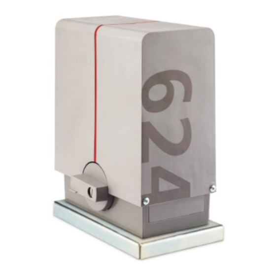
LINCE
Quick installation and programming guide
This quick guide is a summary of the complete installation manual. The manual contains safety warnings and
other explanations which must be taken into account. The most recent version of this guide and the
installation manual are available at the "Downloads" section on Erreka's website:
http://www.erreka-automation.com
WARNING
The options and functions described in this guide apply for the firmware version indicated on the circuit. The
firmware, as part of a process of continuous improvement, is subject to new functionalities or upgrades being
included as a result of new versions which are not necessarily compatible with previous ones. For this reason,
some options or functions may differ or be unavailable if your firmware is older than shown in this guide.
Electrical cabling
A: Main power supply
B: Flashing light
C: Photocells (Tx / Rx)
D: Pushbutton/wall key
E: Antenna
Assembly levels
Unlocking
Unlocking for manual operation:
• Insert the key (1) and turn clockwise 90º, without
forcing it: the cylinder will protrude a few millimetres.
• Turn the key anti-clockwise 90º and remove.
• Turn the handle (2) clockwise 270°, through to the
stopper.
O
BEWARE: the base plate is not
symmetric (a > b)
C71A
Unlocking
D71A
• Turn the handle (2) anti-clockwise 270°, through to
• Push the cylinder (3) inward and manually move the
• Activate a key device in order for the gate to carry out
Elements of the complete installation
Locking
Motorised operation locking:
the stopper.
gate to interlock it in the drive mechanism.
a "reset".
English
E71A
D71B
5
Advertisement
Table of Contents

Related Manuals for Erreka LINCE


Summary of Contents for Erreka LINCE
- Page 1 This quick guide is a summary of the complete installation manual. The manual contains safety warnings and other explanations which must be taken into account. The most recent version of this guide and the installation manual are available at the "Downloads" section on Erreka's website: http://www.erreka-automation.com WARNING The options and functions described in this guide apply for the firmware version indicated on the circuit.
- Page 2 General connections Disconnect power supply before connecting disconnecting component. DL13 24Vac power supply DL36 5Vdc power supply DL37 Closing relay activated DL38 Opening relay activated L: Line F: Main fuse N: Neutral 230VAC: 2,5A T: Earth 125VAC: 4A Display indications D1 and D2: (static) Gate closed...
- Page 3 Rotation direction change and check (C1) This operation is only necessary if the operator opens the leaf instead of closing it when making a reset (rS). P71X P71Z P71Y P71W P71V Total opening radio code programming, P1 (with RSD receiver only, C801) ...
- Page 4 Complete programming chart Pre- Parameter determined Options or values option Motor rotation direction Opening safety device (photocell or strip) Device not installed Device without testing Device with testing Closing safety device (photocell or strip) Device not installed Device without testing Closing photocell with C520 or C521, also prevents the gate from opening Device with testing...
Need help?
Do you have a question about the LINCE and is the answer not in the manual?
Questions and answers