
Related Manuals for Alto-Shaam HSM-24/5S


Summary of Contents for Alto-Shaam HSM-24/5S
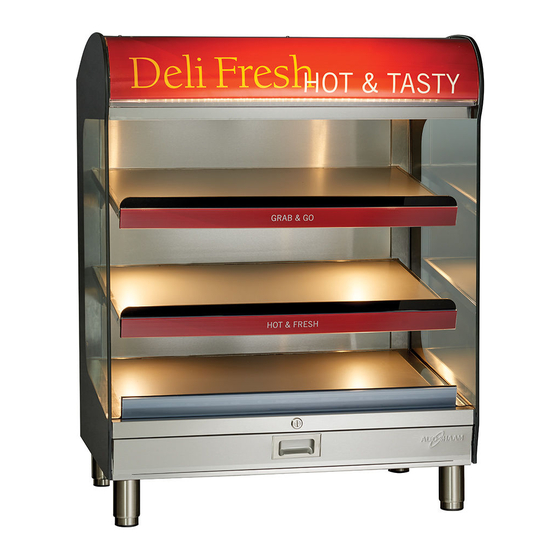
- Page 1 Service Manual Heated Shelf Merchandiser HSM-24/5S HSM-36/5S HSM-48/5S HSM-24/3S-CT HSM-36/3S-CT MN-39054 REV.01 4/17 alto-shaam.com...
-
Page 2: Manufacturer's Information
Alto-Shaam, Inc. P.O. Box 450 W164 N9221 Water Street Menomonee Falls, WI 53052 Original instructions The content in this manual is written in American English. User profile The servicer of this appliance must be a qualified and trained Alto-Shaam service partner. -
Page 3: Forward
Call 800-558-8744 to reach our twenty-four hour emergency service call center for immediate access to local authorized service agencies outside standard business hours. The emergency service access is provided exclusively for Alto-Shaam equipment and is available throughout the United States through Alto-Shaam’s toll free number. Availability Emergency service access is available seven days a week, including holidays. - Page 4 ORWARD Heated S h el f M erch an di s er S e r v ice Man u a l MN-390 54 R ev 1 4 /17...
-
Page 5: Table Of Contents
Theory HSM-24/5S (208-240V, 230V) ......20 HSM-36/5S (208-240V, 230V) ......22 HSM-48/5S (208-240V, 230V) . - Page 6 ABLE OF ONTENTS Heated S h el f M erch an di s er S e r v ice Man u a l MN-390 54 R ev 1 4 /17...
-
Page 7: Safety
AFETY The Meaning of Signal Words Technical content produced by Alto-Shaam contains signal words where needed. These signal words must be obeyed to reduce the risk of death, personal injury, or equipment damage. The meaning of these signal words is explained below. -
Page 8: Safety Precautions
Installation or repairs that are not performed by an authorized service partner or trained technician, or the use of non-factory authorized parts will void the warranty and relieve Alto-Shaam of all liability. When working on this merchandiser, observe precautions in the manual, on tags, ▪... - Page 9 AFETY Electrical usage An identification tag is permanently mounted on the cabinet. Permanent wiring or electrical outlets for this merchandiser must be installed by a licensed electrician in accordance with local, country, or national codes. This merchandiser must be connected to a dedicated circuit: (see below) HSM-48: 30 Amp circuit ▪...
- Page 10 3.0– 4.0 cord, no plug HSM-36/5S 50/60 15.0 CEE 7/7 NEMA 6-20P 208– 240 10.8– 12.5 2.3– 3.0 20A - 250V HSM-24/5S 50/60 11.5 CEE 7/7 NEMA 6-20P 208– 240 8.8– 9.2 1.9– 2.5 20A - 250V HSM-36/3S-CT 50/60 NEMA 5-20P 15.0...
-
Page 11: Operation
PERATION Operating the Merchandiser 1. Make sure the merchandiser is connected to the appropriate power source. 2. Locate the power switch below the top canopy of the left side of the merchandiser. 3. Press the power switch to the ON (l) position. 4. -
Page 12: Components
OMPONENTS Component Identification HSM-48/5S HSM-24/5S HSM-36/3S-CT HSM-24/3S-CT HDC-PHD-000538 H ea t e d S h el f M er c h a n di s e r S e r v ice Man u a l MN-390 54 R ev 1... - Page 13 OMPONENTS (RTD) Temperature sensor, 1000 ohm LED lights, non-polarized terminals LED light bar, Polarity specific wiring Positive wire (+) denoted by the white stripe. 3-inch box fan, impedance protected Airflow direction specific. HDC-PHD-000579 Heate d S h el f M er chan d i se r Se rvice Manu al MN -3 9054 Rev 1...
-
Page 14: Hsm-Ct Component Access Panels
OMPONENTS HSM-CT Component Access Panels Rear Service Panel ON/OFF Switch Control Panel Temperature Sensor HDC-PHD-000542 Heated S h el f M erch an di s er S e r v ice Man u a l MN-390 54 R ev 1 4 /17... -
Page 15: Hsm-5S Component Access Panels
OMPONENTS HSM-5S Component Access Panels Top Service Panel Rear Service Panel ON/OFF Switch Control Panel Temperature Sensor HDC-PHD-000546 Heate d S h el f M er chan d i se r Se rvice Manu al MN -3 9054 Rev 1 4/17... -
Page 16: Hsm-Electrical Assembly
OMPONENTS HSM—Electrical Assembly HSM-24/5S, HSM-36/5S, HSM-48/5S Terminal Blocks ABCDE CD E Heating Pad White Wire HSM 24 Heating Pads Fuses Fans Fuse L2/N 208-240V Lights 230V HDC-PHD-000567 Heated S h el f M erch an di s er S e r v ice Man u a l... -
Page 17: Hsm Electrical Assembly Cont
OMPONENTS HSM Electrical Assembly Cont. HSM-24/3S-CT Electrical Assembly MAIN TERMINAL BLOCK TB10 FB TB11 TB12 TB13 A B C Terminal Blocks HSM-36/3S-CT Electrical Assembly MAIN TERMINAL BLOCK TB10 FB TB11 TB12 TB13 A B C Terminal Blocks HDC-PHD-000550 Heate d S h el f M er chan d i se r Se rvice Manu al MN -3 9054 Rev 1... -
Page 18: Temperature Controller
OMPONENTS Temperature Controller Indicator light Temperature control knob HDC-PHD-000571 Heated S h el f M erch an di s er S e r v ice Man u a l MN-390 54 R ev 1 4 /17... -
Page 19: Heating Pads
OMPONENTS Heating Pads EL-36461 120 & 240 Volt, 550 Watts HSM- 24 Wire WH to either BLK BLK to BLK EL-37091 240 Volt, 750 Watts HSM-36 Wire BLK to BLK EL-37134 240 Volt, 1000 Watts HSM- 48 Wire BLK to BLK HDC-PHD-000577 Heate d S h el f M er chan d i se r Se rvice Manu al... -
Page 20: Theory
HEORY HSM-24/5S (208-240V, 230V) Electrical power is supplied into the unit to the main terminal block, the contactor and the ON/OFF switch. When the ON/OFF switch is selected to the ON position, line voltage is supplied to the A1 and A2 terminals of the contactor. The contactor activates and supplies power to L1 and L2/N terminal blocks, the fans, and the 12 VDC power supply. - Page 21 HEORY Reference image only. Use the electrical schematic for troubleshooting. Terminal L2/N Blocks Relay HDC-WD-000597 Heate d S h el f M er chan d i se r Se rvice Manu al MN -3 9054 Rev 1 4/17...
-
Page 22: Hsm-36/5S (208-240V, 230V)
HEORY HSM-36/5S (208-240V, 230V) Electrical power is supplied into the unit to the main terminal block, the contactor and the ON/OFF switch. When the ON/OFF switch is selected to the ON position, line voltage is supplied to the A1 and A2 terminals of the contactor. The contactor activates and supplies power to L1 and L2/N terminal blocks, the fans, and the 12 VDC power supply. - Page 23 HEORY Reference image only. Use the electrical schematic for troubleshooting. Terminal L2/N Blocks Relay HDC-WD-000601 Heate d S h el f M er chan d i se r Se rvice Manu al MN -3 9054 Rev 1 4/17...
-
Page 24: Hsm-48/5S (208-240V, 230V)
HEORY HSM-48/5S (208-240V, 230V) Electrical power is supplied into the unit to the main terminal block, the contactor and the ON/OFF switch. When the ON/OFF switch is selected to the ON position, line voltage is supplied to the A1 and A2 terminals of the contactor. The contactor activates and supplies power to L1 and L2/N terminal blocks, the fans, and the 12 VDC power supply. - Page 25 HEORY Reference image only. Use the electrical schematic for troubleshooting. Terminal L2/N Blocks R R R e e e la l l l a a a y y y y Re la la y y HDC-WD-000605 Heate d S h el f M er chan d i se r Se rvice Manu al MN -3 9054 Rev 1...
-
Page 26: Hsm-24/3S-Ct (120V)
HEORY HSM-24/3S-CT (120V) Electrical power is supplied into the unit and connected at the main terminal block. When the ON/OFF switch is selected to the ON position, line voltage is supplied to the L1 terminal block, the fans, and the 12 VDC power supply. The L2/N terminal block acts as neutral. - Page 27 HEORY Reference image only. Use the electrical schematic for troubleshooting. Terminal L2/N Blocks Relay HDC-WD-000584 Heate d S h el f M er chan d i se r Se rvice Manu al MN -3 9054 Rev 1 4/17...
-
Page 28: Hsm-24/3S-Ct (208-240V, 230V)
HEORY HSM-24/3S-CT (208-240V, 230V) Electrical power is supplied into the unit and connected at the main terminal block. When the ON/OFF switch is selected to the ON position, line voltage is supplied to the L1 and L2/N terminal blocks, the fans, and the 12 VDC power supply. - Page 29 HEORY Reference image only. Use the electrical schematic for troubleshooting. Terminal L2/N Blocks Relay HDC-WD-588 Heate d S h el f M er chan d i se r Se rvice Manu al MN -3 9054 Rev 1 4/17...
-
Page 30: Hsm-36/3S-Ct (208-240V, 230V)
HEORY HSM-36/3S-CT (208-240V, 230V) Electrical power is supplied into the unit and connected at the main terminal block. When the ON/OFF switch is selected to the ON position, line voltage is supplied to the L1 and L2/N terminal blocks, the fans, and the 12 VDC power supply. - Page 31 HEORY Reference image only. Use the electrical schematic for troubleshooting. Terminal L2/N Blocks Relay HDC-WD-000592 Heate d S h el f M er chan d i se r Se rvice Manu al MN -3 9054 Rev 1 4/17...
-
Page 32: Schematics
CHEMATICS HSM-24/5S (208-240V, 230V) 12VDC 12VDC 6.3A 6.3A 6.3A 6.3A 5020770 5020770 ( CD-3922 ) ( CD-3922 ) ( CD-36231 ) ( CD-36231 ) ( CD-33925 ) ( CD-33925 ) ( CD-34207 ) ( CD-34207 ) ( CD-33840 ) ( CD-33840 ) -
Page 33: Hsm-36/5S, Hsm-48/5S (208-240V, 230V)
CHEMATICS HSM-36/5S, HSM-48/5S (208-240V, 230V) 12VDC 12VDC 6.3A 6.3A 6.3A 6.3A 3.0A 3.0A 5020770 5020770 ( CD-3922 ) ( CD-36231 ) ( CD-33925 ) ( CD-34207 ) ( CD-33840 ) ( CD-3588 ) HDC-WD-000810 Heate d S h el f M er chan d i se r Se rvice Manu al MN -3 9054 Rev 1... -
Page 34: Hsm-24/3S-Ct (120V)
CHEMATICS HSM-24/3S-CT (120V) L2/N SWITCH SW-36714 LIGHT N.O. N/L2 LI-36912 SN-37077 Controller CC-36830 LIGHT N.O. N/L2 LI-36912 SN-37077 Controller CC-36830 LIGHT N.O. N/L2 LI-36912 SN-37077 Controller CC-36830 62 64 BR BU 12VDC POWER SUPPLY BA-38198 LIGHT LP-37100 TB13 6.3A TB11 TB13 6.3A TB12... -
Page 35: Hsm-24/3S-Ct (208-240V, 230V)
CHEMATICS HSM-24/3S-CT (208-240V, 230V) L2/N SWITCH SW-36714 TB1A LIGHT N.O. N/L2 LI-36912 SN-37077 Controller CC-36830 TB1B LIGHT N.O. N/L2 LI-36912 SN-37077 Controller CC-36830 TB1C LIGHT N.O. N/L2 LI-36912 SN-37077 Controller CC-36830 62 64 BR BU 12VDC POWER SUPPLY BA-38198 LIGHT LP-37100 TB13 6.3A... -
Page 36: Hsm-36/3S-Ct (208-240V, 230V)
CHEMATICS HSM-36/3S-CT (208-240V, 230V) L2/N SWITCH SW-36714 LIGHT N.O. N/L2 LI-36912 SN-37077 Controller CC-36830 LIGHT N.O. N/L2 LI-36912 SN-37077 Controller CC-36830 LIGHT N.O. N/L2 LI-36912 SN-37077 Controller CC-36830 BR BU 12VDC POWER SUPPLY BA-38198 LIGHT LP-37100 TB13 6.3A TB11 TB13 6.3A TB12 LIGHT... -
Page 37: Troubleshooting
ROUBLESHOOTING No Operation Measure the voltage at the outlet. Does the voltage Inform the customer to correspond to the voltage call an electrician. printed on the serial number tag? Measure the voltage between L1 and L2/N at the main terminal block. Does the voltage correspond to the voltage Repair or replace the... -
Page 38: One Shelf Not Heating
ROUBLESHOOTING One Shelf Not Heating Turn the temperature control for the shelf that is not heating to the highest number. Measure the voltage at Is the green indicator the L1 and L2/N terminals light illuminated for the of the temperature shelf that is not heating? controller. -
Page 39: All Lights, Or One Bank Of Lights, Will Not Illuminate
ROUBLESHOOTING All Lights, or one Bank of Lights, will not Illuminate Measure the voltage across the brown and blue wires of the power supply. Does the measured voltage correspond to the voltage Repair or replace the wiring printed on the serial number tag? Measure the voltage across the red and black wires of the power supply Is the measured voltage 12 VDC? -
Page 40: Fans Will Not Turn On
ROUBLESHOOTING Fans Will Not Turn On Measure the voltage at terminal blocks L1 to L2/N. Does the voltage correspond Repair or replace the to the voltage printed on the wiring to the terminal serial number tag? blocks L1 and L2/N. Repair or replace the wiring from terminal Is this a 48”... -
Page 41: Assembly/Disassembly
SSEMBLY ISASSEMBLY Replacing the Shelf Heating Element Disconnect the electrical power Remove the rear service panel. source to the merchandiser. Install lockout/tagout equipment. Remove the electrical service panel Record the terminal blocks that the heating pad wires are installed into. Disconnect the heating pad wires from the terminal blocks. - Page 42 SSEMBLY ISASSEMBLY Continued from previous page Disconnect the RTD temperature Remove the screws securing the sensor wires from the temperature shelf to the back of the unit. controller. (Bottom shelf only) Remove the shelf (Bottom shelf only) Remove the shelf guard assembly.
- Page 43 SSEMBLY ISASSEMBLY Continued from previous page Remove the screws securing the Remove the shelf from the unit. shelf to the support. Remove the screws securing the shelf guard. Remove the shelf guard. Remove the screws from the sides of the shelf. HDC-TS-000656 Continued on next page Heate d S h el f M er chan d i se r...
- Page 44 SSEMBLY ISASSEMBLY Continued from previous page Turn the shelf over. Remove the shelf bottom. Remove the insulation. Remove the heating pad from the shelf. HDC-TS-000658 Continued on next page Heated S h el f M erch an di s er S e r v ice Man u a l MN-390 54 R ev 1...
- Page 45 SSEMBLY ISASSEMBLY Continued from previous page Remove the covering from the heating pad adhesive. Install the heating pad onto the shelf. Install the new RTD temperature sensor. HDC-TS-000660 Continued on next page Heate d S h el f M er chan d i se r Se rvice Manu al MN -3 9054 Rev 1...
- Page 46 SSEMBLY ISASSEMBLY Continued from previous page Install the insulation. Install the shelf bottom. Install the shelf guard. Install the screws securing the shelf guard. Install the screws into the sides of the shelf. HDC-TS-000662 Continued on next page Heated S h el f M erch an di s er S e r v ice Man u a l MN-390 54 R ev 1...
- Page 47 SSEMBLY ISASSEMBLY Continued from previous page Install the shelf into the unit. Install the screws securing the shelf to the support. (Bottom shelf only) Install the shelf (Bottom shelf only) Install the shelf assembly into the unit. guard assembly. HDC-TS-000664 Continued on next page Heate d S h el f M er chan d i se r Se rvice Manu al...
- Page 48 SSEMBLY ISASSEMBLY Continued from previous page Install the screws securing the shelf Connect the RTD temperature sensor to the back of the unit. wires to the temperature controller. Connect the heating pad wires into Install the electrical service panel. the terminal blocks. HDC-TS-000666 Continued on next page Heated S h el f M erch an di s er...
- Page 49 SSEMBLY ISASSEMBLY Continued from previous page Install the rear service panel. Remove the lockout/tagout equipment. Supply electrical power to the Turn the temperature control knob merchandiser. to 10. Test all functions of the merchandiser. This procedure is complete. HDC-TS-000668 Heate d S h el f M er chan d i se r Se rvice Manu al MN -3 9054 Rev 1...
- Page 50 Heated Shelf Merchandiser...
Need help?
Do you have a question about the HSM-24/5S and is the answer not in the manual?
Questions and answers