
Related Manuals for Digital Equipment 5200 Series


Summary of Contents for Digital Equipment 5200 Series
- Page 1 DIGITAL Server 5100/5200 Series Service Maintenance Manual Part Number: ER-B52WW-SM. A01 Digital Equipment Corporation...
- Page 2 The information in this document is subject to change without notice and should not be construed as a commitment by Digital Equipment Corporation. Digital Equipment Corporation assumes no responsibility for any errors that might appear in this document. The software, if any, described in this document is furnished under a license and may be used or copied only in accordance with the terms of such license.
- Page 3 FCC ID: B5XWW1 The FCC wants you to know... This equipment has been tested and found to comply with the limits for a Class B digital device, pursuant to Part 15 of the FCC rules. These limits are designed to provide reasonable protection against harmful interference in a residential installation.
- Page 4 This equipment is in the 2nd Class category (information equipment to be used in a residential area or an adjacent area thereto) and conforms to the standards set by the Voluntary Control Council For Interference by Data Processing Equipment and Electronic Office Machines aimed at preventing radio interference in such residential area.
-
Page 5: Table Of Contents
Contents Preface ......................Product Description Introduction ..................... Reliability/Availability................. Server Expansion ..................Server Management and Security............. Server Configurations..................Server Naming Guidelines ................ Product Model Numbering Convention ............Related Material ....................Latest Product Information and Updates ............Application Server Product Information ............. Updates.................... - Page 6 Contents RAID Configuration Utility ................2-11 BIOS Upgrade Utility ..................2-11 SCSI Select Utility .................... 2-12 Diagnostics ..................... 2-13 SCU Features Introduction ..................... System - DIGITAL Server 5100/5200............System Management Group ..............Diskette Drive Group ................Boot Options Group.................. Integrated Peripherals Group..............Keyboard Features Group ................
- Page 7 Contents Server CPU Voltage and Temerature Ranges for Pentium II ......4-18 CPU Voltage Range ................. 4-18 CPU VRM Range ..................4-19 Advanced Troubleshooting ................4-20 Server Troubleshooting ................... 4-21 Disk Drive Troubleshooting................4-24 SBB Troubleshooting..................4-27 Tape Drive Troubleshooting................4-27 Monitor Troubleshooting ..................
- Page 8 Contents Server SIMMs Requirements ..............5-37 Memory Configuration Guidelines ............. 5-38 Upgrading Memory ................... 5-39 Memory Troubleshooting ................5-39 Installing Additional DIMM Memory..............5-40 Memory Configuration Guidelines ............. 5-41 Memory Configurations................5-42 Memory Troubleshooting ................5-43 Removing and Replacing the Power Supply............. 5-44 Removing and Replacing the Diskette Drive.............
- Page 9 Contents Device Mapping Introduction ..................... Processor Memory Address Map .............. I/O Address Map ..................Server Interrupt Levels ................PCI Configuration Space Address Map ............. Service Notes ....................Figures Typical DIGITAL Server 5100/5200 ................... viii 2-1. SCU Main Menu Options ................... 4-1.
- Page 10 Contents 5-22. Removing and Replacing the CD-ROM Drive............5-49 5-23. Removing and Replacing a Cooling Fan..............5-51 5-24. Removing and Replacing the Secondary Cooling Fan 2........... 5-53 5-25. Removing and Replacing Cooling Fan 5..............5-55 5-26. Removing and Replacing the Speaker..............5-57 5-27.
-
Page 11: Preface
Preface This Service Maintenance Manual is a troubleshooting guide that can be used for reference when servicing DIGITAL Servers. DIGITAL reserves the right to make changes to this Service Maintenance Manual without notice. Accordingly, the illustrations and procedures in this document might not apply to all DIGITAL Servers to be serviced since many of the diagnostic tests are designed to test more than one product. -
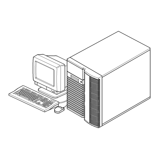
Page 12: Typical Digital Server 5100/5200
Preface DEC00421 Typical DIGITAL Server 5100/5200 viii... -
Page 13: Product Description
Product Description Introduction The DIGITAL Server 5100/5200 is a high-performance, highly-scaleable network and application server featuring the latest in modular processor, and storage technology. The DIGITAL Server provides support for the following features: Reliability/Availability Pentium Pro or Pentium Pentium Pro processor module. Each Pentium Pro II Processor Module processor operates using either 36-bit SIMMs, 60 ns access time, EDO or Fast Page memory. -
Page 14: Server Expansion
Product Description Power Supply The DIGITAL Server ships with one power supply for normal operation. An optional second power supply can be purchased to provide redundant power. Variable Fan Speed Automatically adjusts fan speed according to ambient temperature. Internal Sensors Monitors internal server temperatures, fan operation, and power supply temperatures and voltages. -
Page 15: Server Management And Security
Product Description Capacity for 10 Internal Accommodates one CD-ROM drive (standard), seven SCSI Storage Devices 3½-inch half-height drives in Storage Building Blocks (SBBs), and two narrow (50-pin) half-height, 5¼-inch devices; or one full-height, 5¼-inch device (CD-ROMs or tape drives). External I/O Ports Two serial ports and one parallel port to support external options such as a printer, modem, or local terminal. -
Page 16: Server Configurations
Product Description Server Configurations The following rules apply when Product Family Names and Product Model Names are assigned to DIGITAL Server products. These rules apply to all products developed in the NT Server Business Unit (NTSBU). Server Naming Guidelines • All products in a family carry the same name on the nameplate. -
Page 17: Product Model Numbering Convention
Product Description Product Model Numbering Convention The following example describes the product model numbering convention: DIGITAL SERVER 1234 5678A R 1 = PRODUCT FAMILY NAME (first character of family number) 2 = MAJOR PROCESSOR TECHNOLOGY DIFFERENTIATOR WITHIN THE FAMILY This number will be assigned to each new platform based on the following matrix. Open numbers will be assigned as new processor technology is introduced. - Page 18 Product Description 5 = CPU TYPE BLANK = PENTIUM 1= PENTIUM PRO 2 = PENTIUM II/SLOT 1 3 = PENTIUM II/SLOT 2 4 = Open/Available for future processors 5 = Open/Available for future processors 6 = ALPHA EV56 7 = ALPHA PCA57 8 = ALPHA EV6 9 = ALPHA EV67 6, 7, 8,9 = CPU CLOCK SPEED IN MHZ...
-
Page 19: Related Material
Product Description Related Material The following related material is available: Document or Software Title Order Number Description Service Quick Reference ER-B52WW-SR (English only) Provides troubleshooting information that can be used when servicing DIGITAL servers. This manual is a condensed version of the Service Maintenance Manual and is provided in a pocket-size format (4 x 8- inches). - Page 20 Product Description Document or Software Title Order Number Description DIGITAL ServerWORKS software QB-4WY9A-SA Contains ServerWORKS Quick (Multilanguage)* Launch and ServerWORKS Manager software and documentation. Quick Launch consists of a bootable CD-ROM disk and Getting Started guide. This program steps the user through the initial server setup and operating system installation.
-
Page 21: Latest Product Information And Updates
Product Description Latest Product Information and Updates Listed below is the current product information and update source locations. Application Server Product Information Family Name Model Name Part Number Description Prioris Family Name DIGITAL Server DIGITAL Server FR-B50WW-AX 6200/256 (PP) - KERNAL Prioris HX 6000 Series 5000 5100 1200... -
Page 22: Updates
Product Description Family Name Model Name Part Number Description Prioris Family Name DIGITAL Server DIGITAL Server FR-J2B6W-AA 6300/512 (P2) - 5000 5200 2300 KERNAL DIGITAL Server DIGITAL Server FR-J2B6W-AX 6300/512 (P2) - 5000 5200 2300 MODEL 1 PowerGrade Chip DIGITAL Server FR-PCB5U-AA 6200/512 (PP) Prioris HX 6000... -
Page 23: Server Software And Utilities
Server Software and Utilities Introduction This chapter describes the utilities supplied with the server. Server utilities include: • ServerWORKS Quick Launch This software is used to install a network operating system onto the server. The CD-ROM also contains various drivers and on-line documentation. -
Page 24: Serverworks Quick Launch
Server Software and Utilities ServerWORKS Quick Launch ServerWORKS Quick Launch is used to install the server’s Network Operating System (NOS). In addition to providing quick and seamless NOS installation, Quick Launch also provides drivers, documentation, and the ability to make diskettes of utilities such as diagnostics. -
Page 25: When To Run The Scu
Server Software and Utilities When to Run the SCU Always run the SCU each time you add, remove, or relocate ISA, PCI and/or EISA expansion boards to reconfigure server resources (IRQs). You should also run the SCU if the main logic board has been changed or after adding memory to an installed processor module. -
Page 26: Configuring Expansion Boards
Server Software and Utilities Configuring Expansion Boards Each time you add, remove, or relocate any EISA/ISA/PCI expansion board, you need to run the SCU to identify their operating characteristics, server resource requirements, and slot locations. Based on this information, the SCU will then automatically assign the proper server resources to EISA expansion boards, enable PCI boards, and inform you as to what jumper or switch settings need to be manually set on ISA expansion boards to avoid resource conflicts. -
Page 27: Starting The Scu
Server Software and Utilities Starting the SCU The SCU is located on the ServerWORKS Quick Launch CD-ROM disk. The SCU options are shown in Figure 2-1. If this is your first time using the SCU, it is recommended that you select “Learn About Configuring your Computer” for detailed information on using the SCU. - Page 28 Server Software and Utilities Welcome Screen Main Menu Configure Configure Maintain System Set Date Set Time Computer Computer Configuration Diskette With System Default See Note See Note Step 1: Important EISA Configuration Information Learn About Configuring Step 2: Add or Remove Boards Your Computer Step 3: View or Edit Details Step 4: Examine Switches or Print Report...
-
Page 29: Using The Scu
Server Software and Utilities Using the SCU To use the SCU: 1. Turn on the server and allow the Power-On Self Test (POST) to complete. If POST detects an error take the appropriate steps to correct the problem. After the problem has been resolved, restart the server. 2. -
Page 30: Scu Keyboard Function Keys
Server Software and Utilities SCU Keyboard Function Keys The following table lists the keyboard function keys used to scroll through the menu screens, and select specific menu items in the SCU. Keyboard Key Function ↓ Moves the cursor down one menu item. ↑... -
Page 31: Configure Computer
Server Software and Utilities Configure Computer This option provides step-by-step instructions on how to configure the server when adding, removing, or relocating expansion boards and when changing operating parameters. Select one of the following menu options: • “Configure Computer with System Default” Loads the SCU default settings. -
Page 32: Maintain System Configuration Diskette
Server Software and Utilities Maintain System Configuration Diskette Select this option to maintain Configuration (CFG) files and System Configuration Information (SCI) files. To access this menu item: 1. Start the SCU using one of the three methods described in “Starting the SCU.”... -
Page 33: Raid Configuration Utility
Server Software and Utilities RAID Configuration Utility RAID-ready DIGITAL Servers include a RAID adapter and RAID configuration utility. The RAID configuration utility appears when you boot the server with the ServerWORKS Quick Launch CD-ROM disc. Use this utility to configure your RAID array. -
Page 34: Scsi Select Utility
Server Software and Utilities When upgrading the BIOS, you must remove any video option cards and enable the onboard VGA. In the rare event that you may need to use the crisis recovery diskette, the server will require that the onboard VGA be used in this mode. SCSI Select Utility The DIGITAL server comes with two onboard Adaptec 7880 SCSI controllers and a SCSI Select configuration utility. -
Page 35: Diagnostics
Server Software and Utilities Diagnostics Diagnostic software is shipped with every DIGITAL Server on the Quick Launch CD- ROM. This software contains an advanced set of diagnostic utilities for identifying and correcting problems with the server. The diagnostic software can be used to verify proper hardware installation and isolate intermittent problems that are not detected by the Power-On Self Test (POST). - Page 36 Server Software and Utilities To run the diagnostics from the DOS partition, perform the following: 1. At the MS-DOS prompt, type: C:\diag\diagnose.bat 2. After the server boots, choose MS-DOS from the boot selection. 3. Once the diagnostics begin, the main screen appears. Refer to Chapter 4, “Troubleshooting,”...
-
Page 37: Scu Features
SCU Features Introduction After entering the SCU, you can edit a variety of resources and configure the server for the most optimized condition. The following tables list the SCU options that are available in the SCU. -
Page 38: System - Digital Server 5100/5200
SCU Features System - DIGITAL Server 5100/5200 Menu Fields Settings Comments System Not user selectable Displays the type of the processor processor type that is resident on the processor module. System Not user selectable Displays the clock of the processor processor clock that is resident on the processor module. -
Page 39: System Management Group
SCU Features System Management Group Menu Fields Settings Comments System Asset Number Select [Enter] to display the Asset number of information the server and the System ID. The Asset number can be changed by the user. Main logic Asset Number Select [Enter] to display main logic board board information including Asset number, Serial... -
Page 40: Diskette Drive Group
SCU Features Diskette Drive Group Menu Fields Settings Comments Enabled (1) Integrated Enables or disables the onboard diskette diskette Disabled controller. The onboard diskette controller controller must be disabled if an external diskette controller performs the interfacing to the diskette drives. Diskette drive A Not Installed Sets the size and density of diskette... -
Page 41: Boot Options Group
SCU Features Boot Options Group Menu Fields Settings Comments A: then C: (1) Boot option Each time the server boots, it will load the C: then A: operating system from the sequence selected. C: only Note, if “C: then A:” is selected, the Quick A: only Launch CD-ROM might not be bootable. -
Page 42: Integrated Peripherals Group
SCU Features Integrated Peripherals Group Menu Fields Settings Comments VGA or EGA (1) Video type Sets the video controller type. CGA 80 columns Monochrome Color (1) Monitor type Sets the type of monitor connected Monochrome to the server: Color or Monochrome. - Page 43 SCU Features Menu Fields Settings Comments Serial port 2 Disabled Enables or disables onboard serial Enable at: 3F8h-3FFh port 2 at the specified address and (IRQ4) (1) IRQ. Enable at: 2F8h-2FFh (IRQ3) Enable at: 3E8h-3Efh (IRQ4) Enable at: 2E8h-2Efh (IRQ3) Enabled (1) Embedded PCI When enabled, this device will be...
-
Page 44: Keyboard Features Group
SCU Features Keyboard Features Group Menu Fields Settings Comments Auto (1) NumLock Selects the power on state for Numlock. If Auto is selected, the server turns on Numlock if it detects a numeric keypad. Disabled (1) Key Click Enables or disables the audible key click Enabled feature. -
Page 45: Shadow Options Group
SCU Features Shadow Options Group Menu Fields Settings Comments Enabled (1) Shadow video The main logic board reserves an area of BIOS ROM Disabled DRAM for a copy of video BIOS ROM. This DRAM called “shadow memory” is write- protected and has the same addresses as the video BIOS ROM locations. -
Page 46: Security Options Group
SCU Features Security Options Group Menu Fields Settings Comments Supervisor Allows you to set a supervisor password. installed (1) password If set, you will be prompted to enter a Installed password prior to accessing the SCU. User password Can only be set in the condition that the installed (1) Supervisor password is set. -
Page 47: Cache Options Group
SCU Features Cache Options Group Menu Fields Settings Comments L1 cache Not user Indicates that the processor L1 cache is selectable; enabled. Always enabled L2 cache Not user Indicates that the processor L2 cache is selectable; enabled. Always enabled Enabled (1) Cache system Enables or disables caching request for BIOS ROM... -
Page 48: Eisa Or Pci Devices Group
SCU Features EISA or PCI Devices Group Menu Fields Settings Comments EISA [slot#] - [device] You can edit resources provided by the expansion board’s vendor. Please refer to the menu displayed on this item. PCI [slot#] - [device] Enabled Whenever PCI devices are installed in the PCI function 1 Disabled PCI slots, the device is automatically... -
Page 49: Troubleshooting
Troubleshooting Introduction This chapter provides troubleshooting information. The sections that follow describe specific problems, probable causes, and recommended actions to pursue if the server fails. Information includes: • Initial Troubleshooting • Diagnostics • Obtain Server Information Using the SCU and Server Management Software •... -
Page 50: Initial Troubleshooting
Troubleshooting Initial Troubleshooting Follow these general procedures to troubleshoot the DIGITAL server. • Record all configuration information and have it readily available. • Turn off the server, wait until all hard disk drives completely spin down, and then turn it back on. •... -
Page 51: Running The Diagnostics
Troubleshooting Running the Diagnostics To run the AMIDiag base package (Emergency Mode diskette) from a diskette, follow this procedure: 1. Insert the diskette labeled “For Emergency Use” in drive A and then boot the server. 2. Use the arrow keys to highlight the desired test. 3. -
Page 52: Running Digital Vendor Extended Tests
Troubleshooting Running DIGITAL Vendor Extended Tests To run DIGITAL Vendor Extended Tests from a diskette: Insert the DIGITAL Vendor Extended Tests diskette for the selected device and then boot the server or type A:\DMENU. 2. Select the desired test. Each diskette has a README.TXT file with a list of devices that can be tested and additional information about each diagnostic. -
Page 53: Obtaining Information About The Server
Troubleshooting Obtaining Information about the Server The DIGITAL Server provides the following system information for the main logic board and the processor module configured on the server: • Asset number User definable field for tracking these components • Part number DIGITAL part number •... -
Page 54: Digital Server Component Information
Troubleshooting The main logic board and processor module each contain memory where specific information and System ID information is stored. The main logic board also stores the server’s System Asset number (see Figure 4-1). Information is available for the server’s main logic board and processor module (such as part numbers, revisions, serial numbers, etc.). -
Page 55: Obtaining Information Using The Scu
Troubleshooting Obtaining Information Using the SCU You can use the SCU to check the Serial number, Revision number, and Asset number for the main logic board and Pentium Pro processor configured in the server. For example, if you change the main logic board or processor module in the server, you must run the SCU to re-synchronize the System ID (server model number and serial number) in the main logic board or processor module’s memory. -
Page 56: Displaying Server Status Using The Hardware
Troubleshooting DIGITAL ServerWORKS Manager allows the Network or Server Administrator to perform the following functions on the server: • Manage DIGITAL PC print, file, and application servers supported by DIGITAL servers using a Windows-based graphical user interface (GUI) for point and click simplicity. •... -
Page 57: Server Status Messages
Troubleshooting Server Status Messages Component Possible Failures Result Main logic board The voltages are outside of the power An error message displays and a voltages: +12, +5, good range. warning beep sounds. +3.3, and -12V The voltage exceeds the upper limit. The server will shutdown after 5 minutes. - Page 58 Troubleshooting Component Possible Failures Result For Pentium Pro: CPU temperature The temperature exceeds The backup fans will activate without sensing 82 °C (179.6 °F). any warning. If the temperature drops below 80 °C (176 °F), the backup fans will be turned off.
-
Page 59: Post Ocp Messages
Troubleshooting POST OCP Messages For the Pentium Pro processor, the following table lists the messages, both normal and error, that will display on the server’s OCP panel during POST and any beeps that might sound when an error occurs. NOTE: To disable the speaker, press the middle button located below the OCP once after a beep sounds. - Page 60 Troubleshooting POST Count Normal OCP OCP Error Beep Code Descriptions Down Display Display Codes Code Shadow ROMs Shadow ROMs test Test DRAM refresh 512K 512-640K DRAM and 640K Extended memory test Ext. mem test Memory test fail Set cache registers Set cache regs.
- Page 61 Troubleshooting The following table lists the messages that appear during POST in support of the Pentium II processor module only. POST Message Description PROC 01 present (ID:xxxx, L2:xxxKB) Indicates 1 or 2 processor(s) found. PROC 02 present (ID: xxxx, L2:xxxKB) The ID is the processor ID value that indicates the stepping of the processor.
-
Page 62: Ocp Messages
Troubleshooting OCP Messages During certain failure conditions, including out-of-range conditions, an error message will display on the OCP panel and a corresponding error code will sound from the server’s speaker. NOTE: To disable the speaker, press the middle button located below the OCP once after a beep sounds. -
Page 63: Ocp Status And Error Messages
Troubleshooting OCP Status and Error Messages Status Normal OCP OCP Error Description of Display Display Error Display/Action CPU ambient temperature For Pentium Pro: CPU1 temp=xxxC CPU1 over heat Temperature of CPU 1 is out of range. CPU2 temp=xxxC CPU2 over heat Temperature of CPU 2 is out of range. - Page 64 Troubleshooting Status Normal OCP OCP Error Description of Display Display Error Display/Action For Pentium Pro: No CPU exists No CPUs are present in the server. Action: Reboot server and check if the failed CPU is still malfunctioning during POST. For Pentium II: No PROC detected No processor(s) present in the server.
-
Page 65: Server Cpu Voltage And Temperature Ranges For Pentium Pro
Troubleshooting Server CPU Voltage and Temperature Ranges for Pentium Pro The following tables list the CPU and Voltage Regulator Module (VRM) operating voltage and temperature ranges for the Pentium Pro. CPU Voltage Range Nominal Nominal Tolerance Normal Voltage Server Error Server Shutdown Percentage Range... -
Page 66: Server Cpu Voltage And Temerature Ranges For Pentium
Troubleshooting Server CPU Voltage and Temerature Ranges for Pentium II The following tables list the CPU and Voltage Regulator Module (VRM) operating voltage and temperature ranges for the Pentium II. CPU Voltage Range Nominal % Range % Based Voltage Shutdown Value Hardware Bad Value Range +12V... -
Page 67: Cpu Vrm Range
Troubleshooting CPU VRM Range Power Good Shutdown Hardware Bad 1.80V +1.67 ~ 1.93V > +1.98V < +1.62V 1.85V +1.72 ~ 1.98V > +2.04V < +1.67V 1.90V +1.77 ~ 2.03V > +2.09V < +1.71V 1.95V +1.81 ~ 2.09V > +2.15V < +1.76V 2.00V +1.86 ~ 2.14V >... -
Page 68: Advanced Troubleshooting
Troubleshooting Advanced Troubleshooting DIGITAL has a Customer Replaceable Unit (CRU) process during the warranty period for: • DIGITAL monitors with screens less than 20 inches • Mice • Keyboards • Speakers • Other parts as defined by DIGITAL as CRUs The DIGITAL CRU process provides for overnight shipment of the part directly to the customer site. -
Page 69: Server Troubleshooting
Troubleshooting Server Troubleshooting Problem Possible Cause Action No response when the Server is not plugged in. Turn off the server, plug it in, and server is turned on. then turn it back on again. No power at the wall outlet. Use another wall outlet. - Page 70 Troubleshooting Problem Possible Cause Action Server operates incorrectly Processor module installed Reinstall processor module. after installing a processor incorrectly. module. SCU indicates an error Remove processor module (for after installing a processor Pentum II module, replace the module. terminator and reboot). If server boots without errors, replace processor module.
- Page 71 Troubleshooting Problem Possible Cause Action No response to keyboard Keyboard might be Enter the keyboard password. commands. password protected by a local or remote control program. Keyboard is not connected. Power down the server and connect the keyboard. Keyboard is connected to Power down the server and the mouse port.
-
Page 72: Disk Drive Troubleshooting
Troubleshooting Disk Drive Troubleshooting Problem Possible Cause Action Server does not SCSI device jumpers Refer to the supplied kit installation recognize an internal incorrectly set. instructions. SCSI device. SCSI ID conflicts. Refer to the supplied kit installation instructions and to the storage backplane jumper configuration. - Page 73 Troubleshooting Problem Possible Cause Action Server does not SCSI device jumpers Refer to the supplied kit installation recognize an external incorrectly set. instructions. SCSI device. SCSI ID conflicts. Refer to the supplied kit installation instructions and to the storage backplane jumper configuration. Terminating resistors not Remove terminating resistors.
- Page 74 Troubleshooting Problem Possible Cause Action Server does not boot Boot device not attached to the Run the SCU to define the server from an internal SCSI SCSI adapter at the lowest boot device. hard disk drive. ROM address. PCI/EISA scanning order Refer to the bus scanning incorrect.
-
Page 75: Sbb Troubleshooting
Troubleshooting SBB Troubleshooting Problem Possible Cause Action SBB fault LED lit. Disk drive failed. Replace disk drive. SBB activity and fault LEDs Disk drive hung or has Replace disk drive. lit. failed. SBB fault LED flashing. Disk drive failed and is Replace disk drive. -
Page 76: Monitor Troubleshooting
Troubleshooting Monitor Troubleshooting Problem Possible Cause Action Monitor power indicator is Monitor is turned off. Turn on the monitor. not on. Power cord is not Connect the power cord to the connected. server. No power at wall outlet. Use another outlet. Power indicator is Replace the monitor. -
Page 77: Cd-Rom Troubleshooting
Troubleshooting CD-ROM Troubleshooting Problem Possible Cause Action Cannot access the CD- Device drivers not installed. Install correct device drivers. ROM drive. Error message reading drive x. No disc in the CD-ROM Insert a disc. drive. Incorrect SCSI ID assigned. Make sure correct SCSI ID is assigned. -
Page 78: Diskette Drive Troubleshooting
Troubleshooting Diskette Drive Troubleshooting Problem Possible Cause Action Target diskette drive cannot Diskette is not formatted. Format the diskette. read or write information. Diskette is worn or Try another diskette. damaged. Diskette is write-protected. Slide the write-protect switch so the hole is not visible. -
Page 79: Raid Troubleshooting
Troubleshooting RAID Troubleshooting Problem Possible Action Cause SBB fault LED lit. Disk drive failed. Replace disk drive. SBB activity and fault LEDs Disk drive hung or has Replace disk drive. lit. failed. SBB fault LED flashing. Disk drive failed and is Replace disk drive. -
Page 80: Fru Replacement
FRU Replacement Introduction The following sections list the Illustrated Parts Breakdown (IPB) part numbers and related replacement procedures. NOTE: Customer installable devices, such as expansion boards, memory, and disk drives are discussed in the System Reference Manual. -
Page 81: Server Front View
FRU Replacement Server Front View Figure Orderable Description Legend Spare Part 70-31674-05/-06 Enclosure assembly, frost white 70-31901-05/-06 Enclosure subassembly (without power supply), frost white 70-31898-03 Front bezel assembly, frost white 74-49277-01 Push button (3) 54-23594-01 OCP module 30-43447-01 LCD,DV16100 S2FTLY 70-31897-01 Caster left (front and back) 70-31897-02... -
Page 82: Server Front View
FRU Replacement Figure 5-1. Server Front View... -
Page 83: Server Left-Side View (Pentium Pro Processor)
FRU Replacement Server Left-Side View (Pentium Pro Processor) Figure Orderable Description Legend Spare Part 12-41569-02 Primary fan 12-41569-06 Secondary fan 17-04096-01 Flat 10-pin cable assembly (OCP power/data cable) 21-39151-01 Real-time clock (server battery) (or substitute part 21-39151-02) 54-24568-01/-02 Main logic board 54-24576-01 or Module, 10/100Base-T Ethernet daughter card 54-25310-01... -
Page 84: Server Left-Side View (Pentium Pro Processor)
FRU Replacement DEC01069-2 Figure 5-2. Server Left-Side View (Pentium Pro Processor) -
Page 85: Server Left-Side View (Pentium Ii Processor)
FRU Replacement Server Left-Side View (Pentium II Processor) Figure Orderable Description Legend Spare Part 12-41569-02 Primary fan 12-41569-06 Secondary fan 17-04096-01 Flat 10-pin cable assembly (OCP power/data cable) 21-39151-01 Real-time clock (server battery) (or substitute 21- 39151-02) 54-24568-01/-02 Main logic board 54-24576-01 or Module, 10/100Base-T Ethernet daughter card 54-25310-01... -
Page 86: Server Left-Side View (Pentium Ii Processor)
FRU Replacement DEC01046-2 Figure 5-2. Server Left-Side View (Pentium II Processor) -
Page 87: Server Right-Side/Rear View
FRU Replacement Server Right-Side/Rear View Figure Orderable Description Legend Spare Part 70-31919-01 Side panel lock assembly 12-37977-04 Rear keylock assembly 70-31909-01 Microswitch cable assembly 74-48303-01 I/O expansion board cover bracket 30-43120-01 Power supply (1) 70-31890-01 Wire assembly (three wires) 70-31894-01 Wire assembly (12 wires) 70-31928-01 System power wire assembly... -
Page 88: Server Right-Side/Rear View
FRU Replacement DEC01103-2 Figure 5-3. Server Right-Side/Rear View... -
Page 89: Miscellaneous
3 Channel PCI RAID Ultra Wide adapter with EDRAM (FR-PCTAR-GC) 30-48622-01 DLT 7000 35/70 GB (FR-PCXLT-AD) 30-48985-01 SCSI Bus Expander (FR-PCSBR-AA) FR-CK450-RP RAID Array 450 NT Cluster Kit, pedestal 54-24602-01 PCI Fast Ethernet 10/100 (Digital Equipment Corp.)(FR-DE500-AA) 30-48628-01 PCI Fast Ethernet 10/100 (FR-PCXDN-BA) 5-10... -
Page 90: Labels And Nameplates
FRU Replacement Labels and Nameplates Orderable Spare Part Description 74-49386-43 Nameplate, DIGITAL Server 5000 36-44556-01 Warning label, power switch 36-45369-05 Label, user info guide (right) 36-45369-04 Label, user info guide (left) Service Procedures The following sections provide detailed service instructions for DIGITAL Servers. CAUTION: Static electricity collects on non-conductors such as paper, cloth, or plastic. -
Page 91: Disconnecting External Devices And Power
FRU Replacement Disconnecting External Devices and Power Before removing the side panels, perform the following: 1. Secure the server using the brake (see Figure 5-4). 2. Shut down any applications that are currently running, then shut down the operating system. 3. -
Page 92: Removing The Side Panels
FRU Replacement Removing the Side Panels To remove the side panels, perform the following: WARNING: Removing the side panels activates two interlock switches located at the top-left and top-right of the server. These switches inhibit power to the server when activated. You might injure yourself or damage the server if you attempt to bypass these switches. -
Page 93: Unlocking And Removing The Side Panels
FRU Replacement DEC01025-2 Figure 5-5. Unlocking and Removing the Side Panels 5-14... -
Page 94: Server Front View
FRU Replacement Server Front View Figure Component Legend CD-ROM drive 3½-inch diskette drive Front access 5¼-inch or 3½-inch half-height drive bays 3-way security lock Integral hot-swap device bay for Storage Building Blocks (SBBs) Power, OCP, and reset buttons Brake Operator control panel (OCP) Power indicator 5-15... -
Page 95: Server Front View
FRU Replacement DEC01026-2 Figure 5-6. Server Front View 5-16... -
Page 96: Server Left Side View
FRU Replacement Server Left Side View Figure Component Legend Redundant cooling fans Cooling fans Casters Five EISA expansion slots Pentium Pro processor module or Pentium II processor module Three primary PCI slots Location of main logic board Ethernet daughter card Three secondary PCI slots Power switch interlock 5-17... -
Page 97: Server Left Side View
FRU Replacement DEC01026-3 Figure 5-7. Server Left Side View 5-18... -
Page 98: Server Right Side View
FRU Replacement Server Right Side View Figure Component Legend Rear fan Power interlock switch Power supply Storage backplane SCSI terminator SCSI address jumpers (J181) Storage backplane Jumper cable Power plug Wide SCSI 68-pin connector NOTE: If installing a second redundant power supply, you must remove the rear fan, item J, and disconnect it from the main logic board. -
Page 99: Server Right Side View
FRU Replacement DEC01027-2 Figure 5-8. Server Right Side View 5-20... -
Page 100: Server Rear View
FRU Replacement Server Rear View Figure Component Legend SCSI knockouts (back panel) Keylock 10Base-T connector (RJ45) 10Base-2 connector (BNC) 10Base-5 connector (AUI) Keyboard and mouse ports Parallel port SVGA graphics port Serial ports ac power plug ac power out/monitor plug 5-21... -
Page 101: Server Rear View
FRU Replacement DEC01027-3 Figure 5-9. Server Rear View 5-22... -
Page 102: Main Logic Board Connectors
FRU Replacement Main Logic Board Connectors Figure Legend Connector EISA expansion slots (1 through 5) Remote Server Management (RSM) Primary PCI expansion slots (1 through 3) Serial ports Parallel port and video port Mouse and keyboard ports Ethernet daughter card connector Secondary PCI expansion slots (4 through 6) Diskette drive 68-pin wide SCSI connector (channel B) -
Page 103: Main Logic Board Connectors
FRU Replacement DEC01028-2 Figure 5-10. Main Logic Board Connectors 5-24... -
Page 104: Main Logic Board Components
FRU Replacement Main Logic Board Components Figure Legend Component SVGA graphic controller Ethernet controller SCSI controllers 8031 ROM Dip switch block Real-time clock/server battery BIOS flash ROM DEC01028-3 Figure 5-11. Main Logic Board Components 5-25... -
Page 105: Pentium Pro Processor Module Components And Connectors
FRU Replacement Pentium Pro Processor Module Components and Connectors Figure Component/Connector Legend Eight memory SIMM sockets Pentium Pro processor #1 ZIF socket Pentium Pro processor #2 ZIF socket Voltage Regulator Module (VRM) slot, processor 2 Voltage Regulator Module (VRM) slot, processor 1 Frequency ratio DIP switches DEC01056 Figure 5-12. -
Page 106: Pentium Ii Processor Module Components
FRU Replacement Pentium II Processor Module Components Figure Component/Connector Legend Pentium II processor Pentium II processor slot or terminator card Dip switch for processor settings Four DIMM sockets Voltage Regulator Module (VRM) slot, processor 2 Voltage Regulator Module (VRM) slot, processor 1 DEC001248-2 Figure 5-13. -
Page 107: Ethernet Daughter Card Components And Connectors
FRU Replacement Ethernet Daughter Card Components and Connectors Figure Component/Connector Legend 10/100Base-T connector (RJ45) 10Base-5 connector (AUI) 10Base-2 connector (BNC) DEC01030-2 Figure 5-14. Ethernet Daughter Card Components and Connectors 5-28... -
Page 108: Jumpers And Switch Settings
FRU Replacement Jumpers and Switch Settings The following table lists the main logic board switch settings, jumper settings, and factory-default settings. Figure 5-15 shows the switch and jumper locations. CAUTION: Do not touch any electronic component unless you are safely grounded. Wear a grounded wrist strap or touch an exposed metal part of the server chassis. - Page 109 FRU Replacement Feature Function Setting Description BIOS Disabled SW1-1, off The main logic board’s flash BIOS upgrade switch must Enabled (1) SW1-1, on (1) upgrade be set to the disabled (OFF) position to prevent unauthorized personnel from loading a new server BIOS.
-
Page 110: Main Logic Board Switch And Jumper Locations
FRU Replacement 1 2 3 DEC01028-6 Figure 5-15. Main Logic Board Switch and Jumper Locations 5-31... -
Page 111: Pentium Pro Processor Module Switch Settings
FRU Replacement Pentium Pro Processor Module Switch Settings The following table lists the Pentium Pro processor module switch settings. Figure 5- 16 shows the switch locations. CAUTION: Do not touch any electronic component unless you are safely grounded. Wear a grounded wrist strap or touch an exposed metal part of the server chassis. -
Page 112: Pentium Pro Processor Module Switch Locations
FRU Replacement DEC01029-5 Figure 5-16. Pentium Pro Processor Module Switch Locations 5-33... -
Page 113: Pentium Ii Processor Module Switch Settings
FRU Replacement Pentium II Processor Module Switch Settings The following table lists the Pentium II processor module switch settings. Figure 5-17 shows the switch locations. CAUTION: Do not touch any electronic component unless you are safely grounded. Wear a grounded wrist strap or touch an exposed metal part of the server chassis. - Page 114 FRU Replacement Speed Position Switches J19 Switch Settings 200 MHz (1) 2, 5, 6, 7, 8 DOWN 1, 3, 4 233 MHz (1) 1, 2, 5, 6, 7, 8 DOWN 3, 4 266 MHz 3, 5, 6, 7, 8 DOWN 1, 2, 4 300 MHz 1, 3, 5, 6, 7, 8...
-
Page 115: Pentium Ii Processor Module Switch Settings
FRU Replacement DEC01248-10 Figure 5-17. Pentium II Processor Module Switch Settings 5-36... -
Page 116: Installing Additional Simm Memory
FRU Replacement Installing Additional SIMM Memory Pentium Pro-based DIGITAL Servers support up to 1 GB of EDO memory or Fast- Page memory using single in-line memory modules (SIMMs). The server’s memory can be increased by adding or replacing SIMMs on the installed processor module. The server has a minimum supported memory of 32 MB. -
Page 117: Memory Configuration Guidelines
FRU Replacement Memory Configuration Guidelines NOTE: Before you begin, create an SCU diskette using Quick Launch. You must run the SCU after installing any memory upgrade. This allows the server to recognize the new memory configuration. The memory configuration guidelines for the DIGITAL server are as follows: •... -
Page 118: Upgrading Memory
FRU Replacement Upgrading Memory You can upgrade memory on the DIGITAL server by adding or replacing SIMMs on the installed processor module. You must add two SIMMs (per bank) when expanding memory starting from Bank 0. Memory Troubleshooting The DIGITAL server’s Power On Self Test (POST) can detect memory size, type, and errors when it boots. -
Page 119: Installing Additional Dimm Memory
FRU Replacement To isolate to the failing SIMM, replace one of the two SIMMs which was indicated in the POST error message with a similar SIMM and then rerun POST. If the same error message occurs, replace the second SIMM with the SIMM that was previously removed. -
Page 120: Memory Configuration Guidelines
FRU Replacement Memory Configuration Guidelines NOTE: Before you begin, create an SCU diskette using Quick Launch. You must run the SCU after installing any memory upgrade. This allows the server to recognize the new memory configuration • Supported DIMMs: 168 pin, 72-bit 60 ns access time. EDO memory, ECC protected. -
Page 121: Memory Configurations
FRU Replacement Memory Configurations Bank 0 (J15) Bank 1 (J16) Bank 2 (J17) Bank 3 (J18) Total Memory 32 MB 32 MB 64 MB 64 MB 64 MB 32 MB 96 MB 64 MB 64 MB 128 MB 64 MB 32 MB 32 MB 128 MB... -
Page 122: Memory Troubleshooting
FRU Replacement Memory Troubleshooting The DIGITAL Server’s Power-On Self Test (POST) can detect memory errors when it boots. The error can be isolated to a single DIMM on the processor module. The memory error message format is: <Type of error>: <Location>... -
Page 123: Removing And Replacing The Power Supply
FRU Replacement Removing and Replacing the Power Supply 1. Turn off the server. 2. Remove the ac power cord and monitor cables, if applicable. 3. Unlock and remove the right side panel. 4. Disconnect the wire harness connectors from the power supply. 5. -
Page 124: Removing And Replacing The Power Supply
FRU Replacement Figure 5-20. Removing and Replacing the Power Supply 5-45... -
Page 125: Removing And Replacing The Diskette Drive
FRU Replacement Removing and Replacing the Diskette Drive 1. Turn off the server. 2. Unlock and remove the left side panel. 3. Open the door. 4. Disconnect the power and data cables from the drive. 5. Remove the two screws from the drive bay. 6. -
Page 126: Removing And Replacing The Diskette Drive
FRU Replacement Figure 5-21. Removing and Replacing the Diskette Drive 5-47... -
Page 127: Removing And Replacing The Cd-Rom Drive
FRU Replacement Removing and Replacing the CD-ROM Drive 1. Turn off the server. 2. Unlock and the remove left side panel. 3. Open the door. 4. Disconnect the power and data cables from the CD-ROM drive. 5. Remove the two screws from the drive bay. 6. -
Page 128: Removing And Replacing The Cd-Rom Drive
FRU Replacement Figure 5-22. Removing and Replacing the CD-ROM Drive 5-49... -
Page 129: Removing And Replacing A Cooling Fan
FRU Replacement Removing and Replacing a Cooling Fan The following procedure can be used to remove primary cooling fan 1, secondary cooling fan 4, and primary cooling fan 3. 1. Turn off the server. 2. Unlock and remove the left side panel. 3. -
Page 130: Removing And Replacing A Cooling Fan
FRU Replacement D E C 0 0 7 7 6 Figure 5-23. Removing and Replacing a Cooling Fan 5-51... -
Page 131: Removing And Replacing The Secondary Cooling Fan 2
FRU Replacement Removing and Replacing the Secondary Cooling Fan 2 1. Turn off the server. 2. Unlock and remove the left side panel. 3. Disconnect the fan cable from the main logic board. 4. Remove the screw. 5. Remove the fan from the chassis. 6. -
Page 132: Removing And Replacing The Secondary Cooling Fan 2
FRU Replacement D E C 0 0 7 7 7 Figure 5-24. Removing and Replacing the Secondary Cooling Fan 2 5-53... -
Page 133: Removing And Replacing Cooling Fan 5
FRU Replacement Removing and Replacing Cooling Fan 5 1. Turn off the server. 2. Unlock and remove the left and right side panel. 3. Disconnect the fan cable from the main logic board. 4. Remove the four screws securing the fan and brace to the chassis. 5. -
Page 134: Removing And Replacing Cooling Fan 5
FRU Replacement Figure 5-25. Removing and Replacing Cooling Fan 5 5-55... -
Page 135: Removing And Replacing The Speaker
FRU Replacement Removing and Replacing the Speaker 1. Turn off the server. 2. Unlock and remove the left side panel. 3. Disconnect the speaker cable from the main logic board. 4. Remove the speaker from the chassis. 5. Replace the speaker by performing the removal steps in reverse order. 5-56... -
Page 136: Removing And Replacing The Speaker
FRU Replacement D E C 0 0 7 7 8 Figure 5-26. Removing and Replacing the Speaker 5-57... -
Page 137: Removing And Replacing The Main Logic Board
FRU Replacement Removing and Replacing the Main Logic Board 1. Turn off the server. 2. Disconnect all external cables from the I/O expansion modules located at the rear of server. 3. Unlock and remove the left side panel. 4. Disconnect all cables from the main logic board. 5. -
Page 138: Removing And Replacing The Main Logic Board
FRU Replacement 18. Reconnect all external and internal cable connections. 19. Reinstall and lock the left and right side panel. 20. Turn on the server. 21. Run the SCU to configure the server and restore the system management information. Figure 5-27. Removing and Replacing the Main Logic Board 5-59... -
Page 139: Removing And Replacing The Server Battery/Real Time Clock (Rtc)
FRU Replacement Removing and Replacing the Server Battery/Real Time Clock (RTC) The server’s battery runs the server clock and retains any setup information when it is turned off. If the server ever fails to retain the correct date, time, or configuration settings when it is turned on, you need to replace the server’s battery/RTC. -
Page 140: Replacing The Server Battery/Rtc
FRU Replacement 9. Reboot and run the SCU: a. Select Configure Computer from the SCU screen. b. Select View and Edit Details from the displayed screen. c. Edit the configuration settings to match what was recorded in step 1. d. Select Save and Exit to configure your server. Refer to Chapter 2, “Server Software and Utilities.”... -
Page 141: Removing And Replacing The Storage Backplane
FRU Replacement Removing and Replacing the Storage Backplane 1. Turn off the server. 2. Unlock and remove the right side panel. 3. Record all cable configuration information. 4. Disconnect all cables and terminators. 5. Before removing SBB devices, record how they are configured. 6. -
Page 142: Removing And Replacing The Storage Backplane
FRU Replacement Figure 5-29. Removing and Replacing the Storage Backplane 5-63... -
Page 143: Removing And Replacing A Caster
FRU Replacement Removing and Replacing a Caster 1. Turn off the server. 2. Carefully lay the server on its side. Note that the right and left casters are different. 3. If removing the left- or right-front caster, release the server brake. Otherwise, skip to step 4. -
Page 144: Removing And Replacing A Caster
FRU Replacement D E C 0 0 7 7 9 Figure 5-30. Removing and Replacing a Caster 5-65... -
Page 145: Processor Module Upgrades
Processor Module Upgrades Introduction DIGITAL sells processor upgrade kits known as PowerGrade kits. Installing a PowerGrade kit increases the capabilities of the server. This chapter describes the configuration guidelines that must be followed prior to adding a Pentium Pro or Pentium II processor as well as detailed procedures on removing and installing processor modules. -
Page 146: Boot The Quick Launch Cd-Rom And Create Diskettes
Processor Module Upgrades Boot the Quick Launch CD-ROM and Create Diskettes If the PowerGrade kit contained a new CD-ROM, perform this procedure to obtain new diskettes. During this procedure, you will create a crisis recovery diskette, BIOS upgrade diskette, and a System Configuration Utility (SCU) diskette. The Quick Launch CD-ROM contains the latest BIOS, crisis recovery software, and SCU. -
Page 147: Update The Bios
Processor Module Upgrades Update the BIOS Use the following procedure to update the BIOS: 1. Power up and boot the server with the BIOS Upgrade diskette in drive A. 2. Change the directory to "upgrade": A:\cd upgrade 3. At the MS-DOS prompt, type phlash and press Enter. The following message appears: ***Warning*** You are about to erase the system BIOS in this machine. -
Page 148: Pentium Pro Processor Upgrades
Processor Module Upgrades Pentium Pro Processor Upgrades Installing a higher-performance Pentium Pro processor module increases the capabilities of the server. This section describes the configuration guidelines that must be followed prior to upgrading the server, as well as detailed procedures on removing and installing a Pentium Pro processor module. -
Page 149: Installing A Processor
Processor Module Upgrades Installing a Processor The following sections provide detailed instructions on how to perform a processor installation. Removing the Pentium Pro Processor Module 1. Power down the server. 2. Place the antistatic wrist strap on your wrist and connect the grounding clip to a non-painted metal surface of the server’s chassis. -
Page 150: Removing The Retaining Clip
Processor Module Upgrades Installing a Pentium Pro Processor and Voltage Regulator Module (VRM) 1. Remove the processor from its shipping holder by removing the retaining clip. To remove the clip, press down firmly on the top of the clip. If needed, press down with a small screwdriver in the hole of the second style clip shown in Figure 6-2. -
Page 151: Removing The Processor/Heat Sink Assembly
Processor Module Upgrades 2. Remove the processor/heat sink assembly from its shipping holder. Do not pull the heat sink off of the processor. Use care not to bend the pins. DEC01212-2 Figure 6-3. Removing the Processor/Heat Sink Assembly 3. On the processor module, lift up on the lever of the empty processor socket. Position the pins of the new processor in the socket of the processor module. -
Page 152: Installing The New Processor
Processor Module Upgrades 4. Lower the lever to engage the pins (Figure 6-4). DEC01212-3 Figure 6-4. Installing the New Processor 5. Replace the retaining clip by installing the back side of the clip first, then pressing it into place as shown in Figure 6-5. -
Page 153: Installing The Retaining Clip
Processor Module Upgrades DEC01211-4 DEC01211-5 Figure 6-5. Installing the Retaining Clip 6. Remove the new VRM from its shipping container. 7. Install the VRM into the empty VRM socket (see Figure 6-6). NOTE: A voltage regulator module must be installed for each processor that is installed in the server. -
Page 154: Installing A Vrm
Processor Module Upgrades DEC01032-3 Figure 6-6. Installing a VRM 8. Set all appropriate switch settings on the processor module. 6-10... -
Page 155: Installing The Processor Module
Processor Module Upgrades Installing the Pentium Pro Processor Module 1. Install the processor module into the slot on the main logic board. 2. Secure the processor module to the main logic board using the previously removed retaining bracket and screw. DEC01024 DEC01024-3 Figure 6-7. - Page 156 Processor Module Upgrades Replace the Panel and Reconnect the Cables 1. Install the left side panel and lock the server. The server will not power up with the side panel removed. 2. Connect any cables and power cords previously removed to the back of the server.
-
Page 157: Pentium Ii Processor Upgrades
Processor Module Upgrades Pentium II Processor Upgrades Installing a higher-performance Pentium II processor increases the capabilities of the server. This section describes the configuration guidelines that must be followed prior to adding a processor as well as detailed procedures on removing and installing a Pentium II processor module. -
Page 158: Processor Configurations
Processor Module Upgrades Processor Configurations The server supports two processor configurations: a processor module with one processor or a processor module with two processors. A dual Pentium II processor module is the only upgrade kit available for DIGITAL Servers supporting Pentium II processors. -
Page 159: Upgrading To A Dual Processor Configuration
Processor Module Upgrades Upgrading to a Dual Processor Configuration To upgrade from a single-processor configuration to a dual-processor configuration: 1. Power down the server. 2. Disconnect all external devices, ac power, and monitor power. 3. Remove the side panel. 4. Place the antistatic wrist strap on your wrist and connect the grounding clip to a non-painted metal surface of the server’s chassis. -
Page 160: Removing The Terminator Module
Processor Module Upgrades 6. Remove the terminator module from the processor module (see Figure 6- 10). Grasp the terminator by each end and pull up. DEC001248-6 Figure 6-10. Removing the Terminator Module 6-16... -
Page 161: Installing The Second Processor
Processor Module Upgrades 7. Remove the new processor from its shipping container. 8. Insert the new processor into this slot (see Figure 6-11). 9. Secure the new processor to its socket by pushing out on the two plastic tabs at each side. DEC001248-7 Figure 6-11. -
Page 162: Installing A Vrm
Processor Module Upgrades 10. Remove the new VRM from its shipping container. 11. Install the second VRM into the empty VRM socket (see Figure 6-12). NOTE: A VRM must be installed for each processor installed in the processor module. DEC001248-9 Figure 6-12. -
Page 163: Installing The Processor Module
Processor Module Upgrades DEC01280-4 Figure 6-13. Installing the Processor Module 14. Replace the side panel. 15. Connect all external devices and restore power. Refer to Run the System ID Configuration Utility and Run the System Configuration Utility (SCU) sections later in this chapter to complete the installation. -
Page 164: System Identification (Id) Configuration Utility
Processor Module Upgrades System Identification (ID) Configuration Utility Each system main logic board contains a unique ID called the System ID, which allows application software to determine what system the electronics reside in. This System ID is stored also on CPU cards and memory cards in the system. When the SCU is launched, if there is a mismatch between the System ID on the main logic board and that stored on the CPU and/or memory cards, then the SCU will flag that a mismatch occurred and ask you to enter the correct system part number from the... -
Page 165: Run The System Id Configuration Utility
Processor Module Upgrades Run the System ID Configuration Utility If you upgraded your server with a new cpu type (Pentium Pro to Pentium II) or increased the cache size, you need to run the System ID utility to store the new model in your server memory. -
Page 166: Run The Scu
Processor Module Upgrades Run the SCU Power up and boot the server from the SCU diskette. The SCU enables you to check or change the server’s configuration. Run the SCU to configure the server for the new processor or processor module. To start and run the SCU: 1. -
Page 167: Troubleshooting
Processor Module Upgrades Troubleshooting Using the Crisis Recovery Diskette if Necessary If you updated the BIOS, the Crisis Recovery Diskette may be used only if the server’s BIOS fails or if the BIOS upgrade is unsuccessful. When using the Crisis Recovery diskette, you must remove any video option card and enable the on-board VGA. -
Page 168: Device Mapping
Device Mapping Introduction This chapter provides a series of tables listing map and address information related to server memory and various main logic board devices (such as keyboard controller and interrupt controller). The server memory and address locations are allocated at the factory to operate within a standard environment. -
Page 169: Processor Memory Address Map
Device Mapping Processor Memory Address Map Address Range Function Size 00000 to 9FFFF Main memory 640 KB A0000 to BFFFF PCI/EISA/ISA video buffer memory 128 KB C0000 to C7FFF Video memory BIOS 32 KB C8000 to DFFFF PCI/EISA/ISA expansion board BIOS 96 KB and buffer memory E0000 to EFFFF... -
Page 170: I/O Address Map
Device Mapping I/O Address Map Range (hexadecimal) Function 060 to 064 Keyboard/mouse controller 0F0 to 0FF Math co-processor 1F0 to 1F7 IDE controller (if enabled) 278 to 27F LPT2 (if enabled) COM4 (if enabled) COM2 (if enabled) 378 to 37F LPT1 (if enabled) 3BC to 3BE LPT3 (if enabled) -
Page 171: Server Interrupt Levels
Device Mapping Server Interrupt Levels Interrupt Number Interrupt Source IRQ1 Keyboard controller IRQ3 COM2, COM4 (if enabled) IRQ4 COM1, COM3 (if enabled) IRQ6 Diskette controller (if enabled) IRQ7 LPT1, LPT2, LPT3 (if enabled) IRQ12 Mouse interrupt IRQ13 Math co-processor PCI Configuration Space Address Map PCI Bus No. -
Page 172: Service Notes
Service Notes... - Page 173 Service Notes...
- Page 174 Service Notes...
- Page 175 Service Notes...
Need help?
Do you have a question about the 5200 Series and is the answer not in the manual?
Questions and answers