Table of Contents
Advertisement
Quick Links
Advertisement
Table of Contents
Troubleshooting

Related Manuals for Digital Equipment DECserver 90TL


Summary of Contents for Digital Equipment DECserver 90TL
- Page 1 DECserver 90TL Owner’s Manual Order Number: DSRVE-OM-001...
- Page 2 Le DECserver 90TL n’a pas été conçu pour fonctionner avec des réseaux de télécommunication ou des modules ISDN (Integrated Services Digital Network). A VISO El DECserver 90TL no ha sido diseñado para su uso con redes de IMPORTANTE telecomunicaciones ni dispositivos de Red Digital Servicios Integrados (ISDN).
- Page 3 The information in this document is subject to change without notice and should not be construed as a commitment by Digital Equipment Corporation. Digital Equipment Corporation assumes no responsibility for any errors that may appear in this document. The software described in this document is furnished under a license and may only be used or copied in accordance with the terms of such license.
-
Page 4: Table Of Contents
Contents About This Manual ........1 Overview Features . - Page 5 Offering LAT Services to the Network ....3–17 Offering Services to the Network Through the Telnet Listener ......... . 3–18 Setting Up a Port for SLIP Access by an IP Host .
- Page 6 Figures 1–1 DECserver 90TL Hardware ..... 1–2 DECserver 90TL Connection ....
-
Page 7: About This Manual
Describes troubleshooting techniques. Appendix A Describes communications server specifications. Appendix B Provides a list of reference documentation and ordering information. For additional information on the communications server software, refer to the DECserver 90TL software installation documentation available for this product. - Page 8 Conventions The following are conventions used in this manual. Convention Meaning Special type This special type in examples indicates system output or user input. UPPERCASE Uppercase letters in command lines indicate keywords that must be entered. You can enter keywords in either uppercase or lowercase.
-
Page 9: Overview
Overview This chapter describes hardware, software, and network features of the DECserver™ 90TL Ethernet communications server, referred to as ‘‘communications server’’ throughout this document. Features The communications server supports the following standard features: • Rack mountable in the DEChub™ 90 •... -
Page 10: Decserver 90Tl Hardware
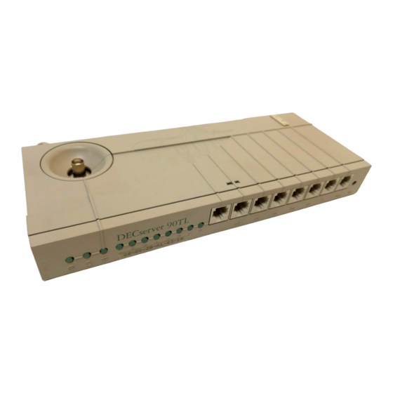
Overview Figure 1–1 shows the communications server and calls out its features. Figure 1–1 DECserver 90TL Hardware L J - 0 1 5 6 7 - T I 0 1–2 Overview... - Page 11 Overview Power Indicator – Lights and remains lit when +5 volts is supplied to the communications server. Self-Test OK Indicator – Lights when the communications server has successfully completed the ROM-based self-tests. Network OK Indicator – Lights when the communications server is connected to an appropriately terminated network.
-
Page 12: Description
Overview Description The DECserver 90TL Ethernet communications server is a multisession communications server designed to operate in multivendor environments. The communications server can be configured as a standalone device or as a module in the DEChub 90 Ethernet backplane. The DEChub™ 90 is a multifunction Ethernet backplane that provides mounting, power, and connections for up to eight Workgroup LAN products. -
Page 13: Decserver 90Tl Connection
Overview Figure 1–2 DECserver 90TL Connection TD/SMP Personal Personal Printer Terminal Computer Computer Terminal Terminal Terminal Terminal DECserver 90TL Ethernet Communications Server ThinWire Ethernet UNIX Host IP Router/Gateway DECnet Router ULTRIX Host VMS Host LJ-01615-TI0 Overview 1–5... -
Page 14: Installation
- or added to the DEChub 90 Ethernet backplane. Before beginning the hardware installation ensure that the software has been properly installed on a load host. Refer to the appropriate DECserver 90TL software installation documentation. -
Page 15: Tabletop Installation
Installation Tabletop Installation To install the communications server (standalone) as a tabletop device, follow the steps below. 1. Connect a ThinWire cable, T-connector, and terminator to the BNC connector on the communications server as shown in Figure 2-1. Connect the other end of the ThinWire cable to an active ThinWire outlet such as a faceplate or other appropriate network device. -
Page 16: Standalone Configuration
Installation Figure 2–1 Standalone Configuration T-Connector 50 Ohm Terminator PJ ,D120 SC ALE 46% 85% International Power Supply North American Power Supply T erminal Reset Switch LJ-01568-TI0 Installation 2–3... -
Page 17: Wallmount Installation
Installation Wallmount Installation To mount the communications server on a wall, follow the steps below. 1. Remove the back cover (refer to Figure 2–2). a. Insert a small screwdriver into the top mounting hole of the cover. b. Lift up the latch on the unit’s back cover. Pull the top of the cover away from the unit and down to remove it. -
Page 18: Removing The
Installation Figure 2–2 Removing the Back Cover L J - 0 0 3 2 0 - T I 0 Installation 2–5... -
Page 19: Backplane Installation
Installation Backplane Installation To install the communications server in the DEChub 90 Ethernet backplane, follow the steps below. 1. Remove the back cover (refer to Figure 2–2). 2. Place the lower mounting tab, located on the back of the communications server, in the appropriate mounting slot on the backplane (refer to Figure 2–3). -
Page 20: Backplane Installation
Installation Figure 2–3 Backplane Installation L J - 0 1 5 1 9 - T I 0 Installation 2–7... -
Page 21: Running Self-Tests
Installation Running Self-Tests The communications server runs a series of self-tests on powerup and reports test status through the communications server LEDs. Refer to Figure 1-1. Ensure that the ThinWire network connection to the BNC connector, or to the DEChub 90, is properly terminated, or connected to an active network. Failure to do this will cause the self-test to fail the network loopback test. -
Page 22: Loading Server Software
Installation Loading Server Software Once the self-tests have completed, the communications server automatically begins the boot sequence to load the software. Software is downline loaded to the communications server from a VMS, ULTRIX, or MS–DOS™ load host using the MOP or BOOTP protocol. If a device is attached to the console port, status messages can be displayed while the boot sequence is running. -
Page 23: Verifying Ports
ISO 8802/3 MOP load or dump Ethernet MOP load or dump For detailed information on installing communications server software, refer to the appropriate DECserver 90TL software installation documentation. The following settings represent default characteristics of the console port. Table 2–2 Default Console Port Terminal Characteristics... -
Page 24: Management
Management This chapter describes the following steps to help you configure and manage the DECserver 90TL Ethernet communications server: • Planning for unit setup. • Configuring the unit for use in your network. • Setting port characteristics. • Connecting interactive devices to the unit. -
Page 25: Setup Planning
Management Setup Planning Before you begin configuring the communications server, you should determine the type of network in which you plan to use the communications server; the types of devices you plan to attach to the communications server such as printers, PCs, terminals, and computers;... -
Page 26: Connecting The Communications Server To Your Network
Management Connecting the Communications Server to Your Network You can use the communications server in a LAT network, in a TCP/IP network, or in a network that includes both protocols. To issue commands to the communications server, connect a terminal into port one of the communications server;... -
Page 27: Tcp/Ip Network
Management TCP/IP Network If you are using the communications server in a TCP/IP network, perform the following steps: 1. The communications server provides a default subnet mask, based on the class of internet addresses used. The default for class A is 255.0.0.0, the default for class B is 255.255.0.0, and the default for class C is 255.255.255.0. -
Page 28: Server Management Options
Management Server Management Options Optionally, you can perform the following: • Specify the MOP maintenance password • Identify the console port • Specify the software image file name • Enable software dumps • Set up event logging at a DECnet system For a detailed description of these topics, refer to "Configuring and Maintaining a Communications Server on a Network"... -
Page 29: Setting Port Characteristics
Management Setting Port Characteristics You can set up devices on the communications server for local access, remote access, or both local access and remote access depending on the port characteristics you set. Local access is used for interactive devices such as terminals;... -
Page 30: Setting Port Access
Management Setting Port Access Set access to a port to one of the following: • LOCAL (default) - for interactive devices, such as terminals. • REMOTE - for noninteractive devices, such as computers and printers. • DYNAMIC - for devices that can be used in interactive and noninteractive mode, such as personal computers (PCs) and printers with keyboards. - Page 31 Management The following shows how to set CHARACTER SIZE to 7 for port 5: Local> CHANGE PORT 5 CHARACTER SIZE 7 The communications server software automatically formats the characters for transmission from the communications server to an internet host or LAT service.
- Page 32 Management The following example shows how to change the STOP BITS to DYNAMIC on port 5: Local> CHANGE PORT 5 STOP BITS DYNAMIC • TYPE Determine the device type: HARDCOPY (for hardcopy devices), ANSI (for ANSI standard video terminals), or SOFTCOPY (for non-ANSI video terminals).
-
Page 33: Setting Flow Control
Management Setting Flow Control The FLOW CONTROL characteristic allows the communications server to start and stop data transfer between the port and the attached device. Using flow control ensures that no data is lost due to lack of buffering space. It does not apply to data between the communications server and a network resource. -
Page 34: Setting Automatic Logout Characteristics
Management Setting Automatic Logout Characteristics You can use various characteristics to automatically log out the port when the device attached to the port is powered off or when there is no activity for a specified period of time. The automatic logout characteristics include the following: •... -
Page 35: Additional Port Customization Settings
Management Additional Port Customization Settings You can use the following commands to customize ports: • AUTOCONNECT—Issue this command when a communications server is unable to locate a particular LAT service. If a previous session has been interrupted, the communications server automatically attempts to reestablish it. -
Page 36: Connecting Interactive Devices
Management Connecting Interactive Devices Interactive devices allow users to directly access the network. Interactive devices are typically terminals, but can be PCs and computers. The communications server is preconfigured to operate with most standard terminals, PCs, or computers. To use a terminal, PC, or computer as an interactive device to access the network, simply connect it into a port on the communications server. -
Page 37: Using An Interactive Device As A Network Service
Management Using an Interactive Device as a Network Service To offer the services of a PC or computer configured as an interactive device to the network, issue the following command: Local> CHANGE PORT port_number ACCESS DYNAMIC Setting port access to DYNAMIC, allows you to toggle the device between a local interactive service and a network service. -
Page 38: Connecting Noninteractive Devices
Management Connecting Noninteractive Devices Noninteractive devices are usually network resources. They include printers, but they can also include PCs and computers if you want to use them as network-wide resources. To configure a noninteractive device, specify the following communications server port characteristics for it: 1. - Page 39 Management 6. For noninteractive communications devices, PCs and computers, enable the SIGNAL CONTROL and DTRWAIT features on the communications server. You can enable DTRWAIT only if you enable SIGNAL CONTROL. To enable SIGNAL CONTROL and DTRWAIT, perform the following: Local> DEFINE PORT port_number SIGNAL CONTROL ENABLED Local>...
-
Page 40: Offering Services To The Network
Management Offering Services to the Network Network services can include remote access to printers, PCs, or computers. You can offer the various devices connected to the communications server as network services to LAT hosts or to TCP/IP hosts. The configuration procedures differ for each type of network protocol. -
Page 41: Offering Services To The Network Through The Telnet Listener
Management Offering Services to the Network Through the Telnet Listener Establish a Telnet Listener using the CHANGE TELNET LISTENER command, as follows: 1. Specify the ports connected to the service, as follows: Local> CHANGE TELNET LISTENER 2010 PORTS port-list ENABLED 2. -
Page 42: Setting Up A Port For Slip Access By An Ip Host
Management Setting Up a Port for SLIP Access by an IP Host When you configure a PC or computer as a dedicated SLIP host, you can communicate directly with the network as an internet host making the communications server virtually transparent. You can configure an interactive device or a noninteractive device as a dedicated SLIP host;... -
Page 43: Security For Interactive And Noninteractive Devices
Management Security for Interactive and Noninteractive Devices You can specify the following security features for interactive devices: • User security levels, which can be privileged, nonprivileged, and secure. • Limited view, which restricts user access to features on the communications server. -
Page 44: Management Tools
Management Management Tools Several management tools can be used to ease communications server management tasks. They include the following: • Communications server commands • Online help • Remote console port (MOP or Telnet) • DSVCONFIG • Terminal Server Manager (TSM) software •... -
Page 45: Online Help
Management Online Help The communications server provides online information about communications server commands. The communications server offers two types of online help: tutorial and reference. Tutorial help provides an overview of end-user tasks. To access tutorial help, enter the following: Local>... -
Page 46: Remote Console Port
Management Remote Console Port The remote console port is a logical port used by the communications server software when communicating using the MOP or Telnet protocol. The remote console port has fixed port characteristics values that you cannot change. You can enter most of the communications server commands at the remote console port. -
Page 47: Communications Server Databases
Management Communications Server Databases Two databases contain all the information the communications server requires to operate: the operational database and the permanent database. The communications server operational database is maintained in random-access memory (RAM). The permanent database is stored in nonvolatile RAM (NVRAM). When the communications server is downline loaded for the first time, these databases contain identical factory-set default settings for all the characteristics, except for the Telnet remote console characteristics. -
Page 48: Operation
Operation This chapter describes communications server operation and how to establish interactive sessions using services on the network. Information covered in this chapter, can be referenced through the HELP TUTORIAL. Basic operational tasks include: • Getting started • Using online help •... -
Page 49: Getting Started
Operation Getting Started Once the communications server has successfully loaded software, you can attach a conventional terminal or PC. Use the following procedure to establish terminal or PC communications with the server: 1. Press Return once or twice. The following prompt appears: Enter Username>... -
Page 50: Establishing Sessions
Operation Establishing Sessions You can establish sessions for either LAT or Telnet. Establishing LAT Sessions Use the CONNECT command to establish LAT service sessions. Prior to creating a LAT session, ensure that the LAT group codes are properly set, as described in Chapter 3. -
Page 51: Establishing A Temporary Slip Session
Operation Establishing a Temporary SLIP Session The communications server supports PCs running SLIP software. The PC sends IP messages to the communications server as Serial Line Internet Protocol (SLIP) packets. The communications server packages the messages as regular IP packets and transmits them over the Ethernet/802.3 network. -
Page 52: Managing Sessions
Operation Managing Sessions To interrupt a service session and return to the Local prompt, press the Break key. Another session can be established with the same host or with a different host. You can establish up to four sessions simultaneously. Additional commands that can be issued at the Local prompt include: •... -
Page 53: Performing File Transfers
Operation Performing File Transfers The communications server supports file transfer using either LAT or Telnet protocols. The following procedure enables you to perform file transfers using the LAT protocol: 1. Ensure that Break is set to LOCAL. Use the SHOW PORT command to determine this. - Page 54 Operation Use the following procedure for file transfers using the Telnet protocol: 1. Ensure that Break is set to LOCAL. Use the SHOW PORT command to determine this. Use the SET PORT BREAK LOCAL command to set Break to LOCAL, if needed. The LOCAL setting is the factory default. 2.
-
Page 55: Troubleshooting
Troubleshooting This chapter provides methods of troubleshooting the DECserver 90TL Ethernet communications server. Also provided in the chapter are symptom and solution information tables for use when isolating communications server hardware, software or network problems. Before servicing the communications server you should: 1. -
Page 56: Decserver 90Tl Troubleshooting
Troubleshooting Table 5–1 DECserver 90TL Troubleshooting If... Then... Do this... The self-test fails, and The ThinWire Ethernet Terminate the network correctly. network LED does not port is not connected to light. a properly terminated network. A fatal hardware error Replace the communications server. - Page 57 Troubleshooting Table 5–1 (Cont.) DECserver 90TL Troubleshooting If... Then... Do this... The communications Terminate the T-connector on the port may not be communications port. terminated. The 50 ohm termina- Reconnect the terminator(s). tor(s) to the T-connector may have disconnected. There is no response at...
- Page 58 Troubleshooting Table 5–1 (Cont.) DECserver 90TL Troubleshooting If... Then... Do this... Ensure, BREAK and AUTOBAUD are DISABLED. Ensure CHARACTER SIZE, PARITY SPEED, STOP BITS and TYPE match printer. Flow control is not set. Set the flow control. The power LED is lit,...
-
Page 59: Physical Specifications
Specifications Specifications for the DECserver 90TL Ethernet communications server are divided into the following categories: • Physical specifications • Environmental specifications • Power specifications • Communications server connector pin out • Cable connector pin out • LAT specifications Physical Specifications Table A–1 Physical Dimensions... -
Page 60: Environmental Specifications
Appendix A Environmental Specifications The communications server is designed to operate in an office environment or in equipment room environments such as telephone closets or satellite equipment rooms. The communications server operating and shipping environments are described in the following tables: Table A–2 Operating Environment Item Value... -
Page 61: Power Specifications
Appendix A Power Specifications The following describes the communications server power specifications. Power Supply Item Value Voltage (North American) 104 Vac to 128 Vac (nominal 120 Vac) Voltage (International) 208 Vac to 256 Vac (nominal 240 Vac) Current at 120 volts .25 amps Current at 240 volts .125 amps... -
Page 62: Communications Server Connector Pin Out
Appendix A Communications Server Connector Pin Out Pin out for the communications server has been designed for compatibility with Open DECconnect™. Figure A–1 shows the circuit connections for each port. Figure A–1 Port Circuit Recv’r Rcv Gnd Driver Tx Gnd Driver Recv’r LJ-01618-TI0... -
Page 63: Cable Connector Pin Out
Appendix A Cable Connector Pin Out This section provides wiring diagrams for the following serial communication cable connectors: Item Description BN25G 8MP-to-8MP (modular plug) Equipment Cable BN24H 8MP-to-6MMP (modified modular plug) Office Cable The BN25G is a twisted-pair (four twisted pairs) cable with standard 8-pin modular plugs. -
Page 64: Bn24H Office Cable Wiring Diagram
Appendix A The BN24H is a twisted-pair (three twisted pairs) cable with a standard 8-pin modular plug on one end and a 6-pin modified modular plug on the other end. This cable is used to connect the communications server to an MMJ connector on an asynchronous device. -
Page 65: Lat Specifications
Appendix A LAT Specifications This section lists default LAT characteristics implemented by the communications server. Table A–4 lists the communications server default characteristics. Table A–4 Default Server Characteristics Characteristic Setting Product type code Node type Master Keepalive timer Master circuit timer 80ms Password 8 characters maximum... -
Page 66: B Related Documentation
Ethernet Communications Server Management AA-PMF1A-TK Ethernet Communications Server Problem Solving AA-PMF2A-TK Ethernet Communications Server Commands AA-PMF3A-TK DECserver 90TL Software Installation (VMS) AA-PMF4A-TE DECserver 90TL Software Installation (ULTRIX) AA-PMF5A-TE DECserver 90TL Software Installation (MS–DOS) AA-PMF6A-TH VMS LAT Control Program (LATCP) Manual... -
Page 67: Canada
Appendix B Canada Call 1-800-267-6146 Mail to: Digital Equipment of Canada LTD 940 Belfast Road Ottawa, Ontario, Canada K1G 4C2 Attn. A&SG Business Manager New Hampshire, Alaska, or Hawaii Call 1-603-884-6660. International Mail to: Digital Equipment Corporation A&SG Business Manager c/o Digital’s local subsidiary... -
Page 68: Index
Index Connectors backplane, 1–3 MJ8 pin out, A–5 Access network, 1–3 setting port, 3–7 port, 1–3 Activity indicators, 1–3 power, 1–3 Asian Terminal, 4–5 Conventions, viii Cover, 2–5 Customize port characteristics, 3–3 Back cover location of, 1–3 Backplane connector, 1–3 Backplane installation Default subnet masks, 3–4 See Figure 2–3, 2–6... - Page 69 Port access, 3–7 LAT specifications, A–7 customized settings, 3–12 LED error codes, 2–8 setting characteristics, 3–6 Loading troubleshooting, 5–2 the DECserver 90TL software, 2–9 Port connector, 1–3 Local access, 3–6 Power connector, 1–3 indicator, 1–3 specifications, A–3 troubleshooting, 5–2 Printer troubleshooting, 5–3...
- Page 70 3–21 ok indicator, 1–3 Troubleshooting troubleshooting, 5–1, 5–2 determining cause and solution, 5–1 to Server Management 5–4 options, 3–5 the DECserver 90TL, 5–1 Services TSM Software, 3–23 offering to network, 3–17 Session establishing LAT, 4–3 establishing SLIP, 4–4 Using establishing Telnet, 4–3...
- Page 71 P.O. Box CS2008 Nashua, New Hampshire 03061 Puerto Rico 809-754-7575 Local Digital subsidiary Canada 800-267-6215 Digital Equipment of Canada Attn: DECdirect Operations KAO2/2 P.O. Box 13000 100 Herzberg Road Kanata, Ontario, Canada K2K 2A6 International ————— Local Digital subsidiary or...
- Page 72 Reader’s Comments DECserver 90TL Owner’s Manual Order Number: DSRVE-OM-001 Please use this postage-paid form to comment on this manual. If you require a written reply to a software problem and are eligible to receive one under Software Performance Report (SPR) service, submit your comments on an SPR form.
- Page 73 If Mailed in the United States BUSINESS REPLY MAIL FIRST CLASS PERMIT NO. 33 MAYNARD MASS. POSTAGE WILL BE PAID BY ADDRESSEE DIGITAL EQUIPMENT CORPORATION Telecommunications and Networks LKG1–3/L12 550 KING STREET LITTLETON, MA 01460–1289 Do Not Tear – Fold Here...
Need help?
Do you have a question about the DECserver 90TL and is the answer not in the manual?
Questions and answers