Table of Contents
Advertisement
Quick Links
Advertisement
Table of Contents

Subscribe to Our Youtube Channel
Related Manuals for Lumel N10A


Summary of Contents for Lumel N10A
- Page 1 POWER NETWORK PARAMETER ANALYSER N10A SERVICE MANUAL...
-
Page 3: Table Of Contents
POWER NETWORK PARAMETER ANALYSER - N10A SERVICE MANUAL CONTENTS 1. APPLICATION ................. 5 2. METER SET ..................6 3. INSTALLATION ................6 3.1. FITTING ................... 6 3.2. EXTERNAL CONNECTION DIAGRAMS ........ 8 4. PROGRAMMING ................13 4.1. FACEPLATE DESCRIPTION ..........13 4.2. -
Page 5: Application
The N10A type meter is a programmable digital instrument destined to measure parameters in three-phase three-wire or four-wire power networks, in symmetric and asymmetric systems. The N10A meter is a version of the N10 meter, in which 3 bi-directional analog outputs have been added for customers’ needs. -
Page 6: Meter Set
2. METER SET The set includes: - N10A type meter 1 pc. - service manual 1 pc. - warranty card 1 pc. - holders to fix into a pannel 4 pcs. Additionally for the execution with interface: - service manual of the serial interface 1 pc. - Page 7 Fig.1 Overall dimensions and fitting way of the N10A meter.
-
Page 8: External Connection Diagrams
3.2. External connection diagrams Direct measurement in a 3-phase network Half-intermediate measurement in a 3-phase network... - Page 9 Fig. 2. Meter connection diagrams in a three-phase network...
- Page 10 Direct measurement in a 4-wire network Half-intermediate measurement in a 4-wire network...
- Page 11 Fig. 3. Meter connection diagrams in a four-wire network...
- Page 12 NOTICE: To make the IBM PC - N10A meter (RS-485) connection it is recommended to use a double-wire twisted conductor in a shield. The shield should be connected to the earth in one point. The shield is necessary when the environment is very perturbed.
-
Page 13: Programming
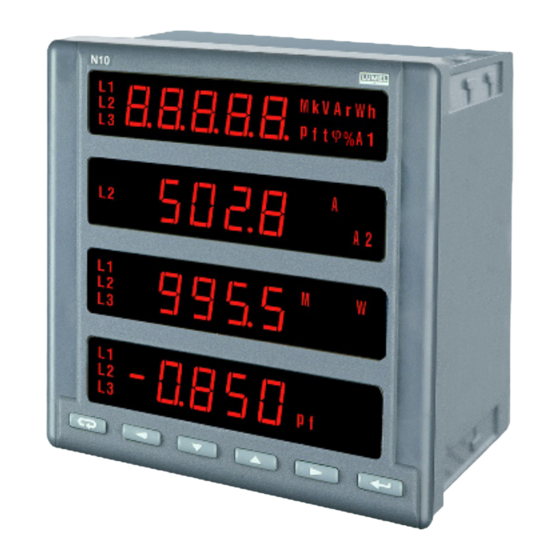
4.1. Faceplate description Fig. 5. View of the N10A meter faceplate The N10A meter has 6 keys, four 5-digits display sections, illuminated symbols and parameter units. Values of measured parameters are shown on active pages selected by successive pressures of the key. -
Page 14: N10A Operating Modes
SETUP procedure. This key enables in anytime the resignation of carried out operations. It cancels alarms in measuring mode. 4.2. N10A operating modes The N10A meter has 5 operating modes represented on the table 2. Table 2 MODE CALLING... -
Page 15: Measuring Mode
After its switching on, the meter carries out tests informing by a message: where: r.1.01 - No of the actual program version After tests carrying out, the meter enters into the measuring mode and displays the page positioned before switching off. The entry into another mode is made in the SETUP procedure. -
Page 16: Measurement Of Voltage And Current Harmonics
key must be pressed and after the key. Alarm is active if it was allocated. One must notice that the alarm do not need to be related to quantities displayed on the page, because a change of page would cause an action on the two-state output. 4.2.1.1. -
Page 17: Time Setting Mode - T
4.2.2. Setting time mode - t After the entry into the SETUP procedure one must choose the mode t by pressing key and the key. Following values will be displayed: Where: yyyy - year mm - month dd - day By means of keys required values can be set, i.e. - Page 18 In the case of 0000 code, password inquiry is omitted. If the access code is different from zero, there is the possibility of parameter reviewing, but changes are locked. Values are set in this mode acc. to the table 3. Table 3 Manu- Designa-...
-
Page 19: Alarm Configuration Mode - A
In parameters 5, 14 the range 0 means that the appropriate output, or interface switched off. Notations: N - lack of parity (no parity), E - bit checking the even parity, O - bit checking the odd parity. The entry into the procedure causes the setting on the parameter 1 or 2 if the access code is equal 0000. - Page 20 Table 4 Manu- Designa- Notice/ Parameter name Range facturer’s tion description values Two-state output 1 - quantity A1_n 0, 1... 34 Quantity code acc. table 5 Two-state output 1 - switch A1on 0... 120 [%] on value Two-state output 1 - switch A1oF 0...
-
Page 21: Page Configuration Mode - P
The A1on < A1oF setting causes the alarm inverse action, i.e. the output is swit- ched on if the prescribed value decreases below the A1on value and the output is switched off if the value, increases above the A1oF threshold. Analog outputs for parameters accepting values: - positive and negative (table 5), are bi-directional, i.e., for negative parameter values, the analog output signal is also negative,... - Page 22 Table 5. Code Quantity name Symbol Unit Signalling Mark Average 3-phase current (k)A L1,L2,L3 3-phase active power (M,k)W L1,L2,L3 3-phase reactive power (M,k)VAr L1,L2,L3 3-phase apparent power (M,k)VA L1,L2,L3 Active power factor (Pf= P/ S) L1,L2,L3 Average 3-phase t factor (t= Q/P) t...
- Page 23 By pressing keys set the number nn of user’s pages from the range 00... 20. Accept by the key the chosen mode. If the number of pages is set 00, it means that the user did not decide to define own pages and chose 7 pages programmed by the manufacturer.
- Page 24 Fig.6 N10A meter working modes.
-
Page 25: Error Codes
5. ERROR CODES During the meter operation, communicates concerning errors can occur. Causes of errors are presented below: Err1 - when the voltage or the current is too low during the measurement: Pfi ,ti below 7% Un and (or) below 2% In below 0,5% THD Ui, THD Ii, below 1% Un, In or the full interval of the PA_t averaging time is not elapsed yet,... - Page 26 Table 6 Measured quantity Range Basic error remarks 100.0 V (Ku=1) Ku = 1...4000 voltage (0.2% m.v. 400.0 V (Ku=1) +0.1% range) for Ku1... 400.0 kV 1.000 A (Ki=1) Ki = 1... 20000 current (0.2% m.v. 5.000 A (Ki=1) +0.1% range) for Ki1...
- Page 27 Serial interface RS-485 Transmission protocol MODBUS Meter reaction to decays and supply recovery: data and meter state preservation during supply decays, (battery support), work continuation after supply recovery Degree of protection ensured by the housing: - frontal side IP 40 - rear side IP 10...
- Page 28 Additional errors in % of the basic error: - input signal frequency < 50% - ambient temperature changes < 50%/10C Electromagnetic compatibility: - immunity acc. EN 61000-6-2 - emission acc. EN 61000-6-4 Safety requirements: acc. EN 61010-1+A1 - insulation ensured by the housing dual - insulation between circuits basic...
-
Page 29: Ordering Codes
7. ORDERING CODES NETWORK PARAMETER METER - N10A Input I current: 1A ( X/1 ) 5A ( X/5 ) acc. order * Input phase voltage U 100 V 400 V acc. order * Digital output: without interface with RS-485 interface Displays: red digits green digits Power supply: 85...250 V d.c., a.c., 40...400 Hz acc. order* Version: standard custom-made Acceptance test: without additional requirements with a quality inspection certificate acc. customer’s agreement ** * after agreement with the manufacturer. -
Page 30: Maintenance And Warranty
In case of some incorrect unit operations: 1. In the period of 12 months from the date of purchase: One should take the meter down from the installation and return it to the LUMEL’s Quality Control Dept. If the unit has been used in compliance with the instructions, LUMEL S.A. - Page 32 According to ISO 9001 and ISO 14001 international requirements. All our instruments have CE mark . For more information, please write to or phone our Export Department Lubuskie Zak³ady Aparatów Elektrycznych LUMEL S.A. ul. Sulechowska 1 65-022 Zielona Góra - Poland Tel.: (48-68) 32 95 100 (exchange)
Need help?
Do you have a question about the N10A and is the answer not in the manual?
Questions and answers