
Related Manuals for IBASE Technology MB886


Summary of Contents for IBASE Technology MB886
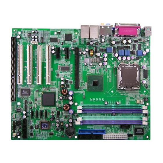
- Page 1 MB886 Socket LGA775 Pentium ® Intel 945G Chipset ® Industrial Motherboard USER’S MANUAL Version 1.1...
- Page 2 Acknowledgments Award is a registered trademark of Award Software International, Inc. PS/2 is a trademark of International Business Machines Corporation. Intel and Pentium 4 are registered trademarks of Intel Corporation. Microsoft Windows is a registered trademark of Microsoft Corporation. Winbond is a registered trademark of Winbond Electronics Corporation.
-
Page 3: Table Of Contents
............5 Installing the CPU ............... 6 ATX Power Installation ............7 Installing the Memory ............7 Setting the Jumpers ............. 8 Connectors on MB886 ............11 Watchdog Timer Configuration ........22 BIOS Setup ............27 Drivers Installation ........49 Intel 945G Chipset Software Installation Utility .... - Page 4 This page is intentionally left blank. MB886 User’s Manual...
-
Page 5: Introduction
Introduction Checklist ® Your MB886 Pentium 4 motherboard package should include the items listed below: • The MB886 motherboard • This User’s manual • 1 Back I/O shield • 1 IDE cable • 1 Floppy cable • 1 SATA cable •... -
Page 6: Product Description
Pentium® D dual core CPU and Pentium® 4 single core CPU. It also supports EMT64 processors. MB886 has four DDR2 memory sockets to support DDR2 400/533/667 SDRAM DIMM modules of up to 4GB in capacity. The board is designed with one Intel 82573L PCI Express Gigabit LAN single controllers. -
Page 7: Specifications
Max. Power Requirement Operating Temperature 0°C~60°C (32°F~140°F) Storage Temperature -20°C~80°C (-68°F~176°F) Relative Humidity 10%~90% (non-condensing) Remarks: MB886 supports Intel® Core™2 Duo processors, Pentium® D dual core CPU and Pentium® 4 single core CPU. It also supports EMT64 processors. MB886 User’s Manual... -
Page 8: Board Dimensions
INSTALLATIONS Board Dimensions MB886 User’s Manual... -
Page 9: Installations
INSTALLATIONS Installations This section provides information on how to use the jumpers and connectors on the MB886 in order to set up a workable system. The topics covered are: Installing the CPU ................ 6 ATX Power Installation ............... 7 Installing the Memory ..............7 Setting the Jumpers .............. -
Page 10: Installing The Cpu
INSTALLATIONS Installing the CPU The MB886 motherboard supports an LGA 775 processor socket for Intel® Pentium® 4 processors. The LGA 775 processor socket comes with a lever to secure the processor. Refer to the pictures below, from left to right, on how to place the processor into the CPU socket. -
Page 11: Atx Power Installation
ATX power connector in a standard ATX power supply (Min. 400watt). Note: The power supply 5VSB voltage must be at least 2A. Installing the Memory The MB886 motherboard supports four DDR2 memory sockets for a maximum total memory of 4GB in DDR memory type. It supports DDR2 533/667. -
Page 12: Setting The Jumpers
INSTALLATIONS Setting the Jumpers Jumpers are used on MB886 to select various settings and features according to your needs and applications. Contact your supplier if you have doubts about the best configuration for your needs. The following lists the connectors on MB886 and their respective functions. - Page 13 INSTALLATIONS Jumper Locations on MB886 JP1, JP2, JP3: RS232/422/485 (COM2) Selection ......10 JP4: IDE DMA Mode Setting .............. 10 JP6: Clear CMOS Contents ..............10 MB886 User’s Manual...
- Page 14 JP6: Clear CMOS Contents Use JP6, a 3-pin header, to clear the CMOS contents. Note that the ATX-power connector should be disconnected from the motherboard before clearing CMOS. Setting Function Pin 1-2 Normal Short/Closed Pin 2-3 Clear CMOS Short/Closed MB886 User’s Manual...
-
Page 15: Connectors On Mb886
INSTALLATIONS Connectors on MB886 The connectors on MB886 allows you to connect external devices such as keyboard, floppy disk drives, hard disk drives, printers, etc. The following table lists the connectors on MB886 and their respective functions. ATX1: 24-pin ATX Power Connector ..........13 ATX2: ATX 12V Power Connector ............ - Page 16 INSTALLATIONS Connector Locations on MB886 ATX1: 24-pin ATX Power Connector ........................13 ATX2: ATX 12V Power Connector ........................13 MB886 Edge Connectors ............................13 CN1: PS/2 Keyboard and PS/2 Mouse Connectors ....................14 CN2, J2, J7, J8: COM1/2/3/4 Serial Ports ......................14 CN3: Parallel Port Connector ..........................15 CN4: VGA CRT Connector ...........................15...
-
Page 17: Atx1: 24-Pin Atx Power Connector
PS-ON Ground Ground Ground Ground Ground Power good 5VSB +12V +12V Ground +3.3V ATX2: ATX 12V Power Connector Signal Name Pin # Pin # Signal Name +12V Ground +12V Ground +12V Ground +12V Ground MB886 Edge Connectors MB886 User’s Manual... -
Page 18: Cn1: Ps/2 Keyboard And Ps/2 Mouse Connectors
CTS, Clear to send DTR, Data terminal ready RI, Ring indicator GND, ground Not Used COM2 is jumper selectable for RS-232, RS-422 and RS-485. Pin # Signal Name RS-232 R2-422 RS-485 DATA- DATA+ Ground Ground Ground RTS- RTS+ CTS+ CTS- MB886 User’s Manual... -
Page 19: Cn3: Parallel Port Connector
CN4 is a DB-15 VGA connector located beside the COM1 port. The following table shows the pin-out assignments of this connector. Signal Name Pin # Pin # Signal Name Green Blue N.C. N.C. DDCDATA HSYNC VSYNC DDCCLK MB886 User’s Manual... -
Page 20: Cn5: Audio Connector
INSTALLATIONS CN5: Audio Connector CN6: 10/100 RJ-45 and USB0/1 Connector CN7: GbE RJ-45 and USB2/3 Connector CN11, CN10, CN9, CN8: SATA0/1/2/3 Connector Pin # Signal Name Ground Ground Ground MB886 User’s Manual... -
Page 21: J1: Digital I/O Connector (4 In, 4 Out)
J3: Audio Front Header Signal Name Pin # Pin # Signal Name MIC2_L Ground MIC2_R Presence# Line2_L MIC2_ID Sense Line2_R Line2_ID J5: USB4/USB5 Connector Signal Name Signal Name Ground Ground J6: USB6/USB7 Connector Signal Name Signal Name Ground Ground MB886 User’s Manual... -
Page 22: J9: Wake On Lan Connector
Speaker: Pins 1 - 4 This connector provides an interface to a speaker for audio tone generation. An 8-ohm speaker is recommended. Pin # Signal Name Speaker out No connect Ground MB886 User’s Manual... - Page 23 Hard Disk Drive LED Connector: Pins 10 and 20 This connector connects to the hard drive activity LED on control panel. This LED will flash when the HDD is being accessed. Pin # Signal Name HDD Active MB886 User’s Manual...
-
Page 24: J11: Irda Connector
Pin # Signal Name No connect Ir RX Ground Ir TX FAN1: CPU Fan Power Connector Pin # Signal Name Control Sense +12V Ground FAN2, FAN3, FAN4: Fan Power Connectors Pin # Signal Name Sense +12V Rotation detection MB886 User’s Manual... -
Page 25: Ide1: Primary Ide Connectors
No connect IDE1 Address 0 Address 2 Chip select 0 Chip select 1 Activity Ground PCIE_1: x16 PCI Express Slot PCIE_2, PCIE_3: x1 PCI Express Slots PCI1, PCI2, PCI3, PCI4: PCI Slots SL1: ISA Slot CN12: CF Socket MB886 User’s Manual... -
Page 26: Watchdog Timer Configuration
(argc != 2) printf(" Parameter incorrect!!\n"); return 1; if (Init_W627EHF() == 0) printf(" Winbond 83627HF is not detected, program abort.\n"); return 1; bTime = strtol (argv[1], endptr, 10); printf("System will reset after %d seconds\n", bTime); EnableWDT(bTime); return 0; //=========================================================================== MB886 User’s Manual... - Page 27 = Get_W627EHF_Reg( 0xF5); bBuf &= (!0x08); Set_W627EHF_Reg( 0xF5, bBuf); //count mode is second Set_W627EHF_Reg( 0xF6, interval); //set timer //=========================================================================== void DisableWDT(void) Set_W627EHF_LD(0x08); //switch to logic device 8 Set_W627EHF_Reg(0xF6, 0x00); //clear watchdog timer Set_W627EHF_Reg(0x30, 0x00); //watchdog disabled //=========================================================================== MB886 User’s Manual...
- Page 28 Init_Finish; W627EHF_BASE = 0x00; result = W627EHF_BASE; Init_Finish: return (result); //=========================================================================== void Unlock_W627EHF (void) outportb(W627EHF_INDEX_PORT, W627EHF_UNLOCK); outportb(W627EHF_INDEX_PORT, W627EHF_UNLOCK); //=========================================================================== void Lock_W627EHF (void) outportb(W627EHF_INDEX_PORT, W627EHF_LOCK); //=========================================================================== void Set_W627EHF_LD( unsigned char LD) Unlock_W627EHF(); outportb(W627EHF_INDEX_PORT, W627EHF_REG_LD); outportb(W627EHF_DATA_PORT, LD); Lock_W627EHF(); MB886 User’s Manual...
- Page 29 (W627EHF_BASE) #define W627EHF_DATA_PORT (W627EHF_BASE+1) //=========================================================================== #define W627EHF_REG_LD 0x07 //=========================================================================== #define W627EHF_UNLOCK 0x87 #define W627EHF_LOCK 0xAA //=========================================================================== unsigned int Init_W627EHF(void); void Set_W627EHF_LD( unsigned char); void Set_W627EHF_Reg( unsigned char, unsigned char); unsigned char Get_W627EHF_Reg( unsigned char); //=========================================================================== #endif //__W627EHF_H MB886 User’s Manual...
- Page 30 Set_W627HF_Reg(0xF1, ((ucDO & 0x0F) << 4)); ucBuf = Get_W627HF_Reg(0xF1) & 0x0F; if (ucBuf != ucDI) ucDI = ucBuf; printf("Digital I/O Input Changed. Current Data is 0x%X\n",ucDI); if (kbhit()) getch(); break; delay(500); return 0; //===================================================================== void ClrKbBuf(void) while(kbhit()) getch(); //--------------------------------------------------------------------------- MB886 User’s Manual...
-
Page 31: Bios Setup
PNP/PCI Configurations .............. 45 PC Health Status ................46 Frequency/Voltage Control ............47 Load Fail-Safe Defaults ..............48 Load Optimized Defaults ............. 48 Set Supervisor/User Password ............48 Save & Exit Setup ................ 48 Exit Without Saving ..............48 MB886 User’s Manual... -
Page 32: Bios Introduction
<PgUp> and <PgDn> keys to change entries, <F1> for help and <Esc> to quit. When you enter the Setup utility, the Main Menu screen will appear on the screen. The Main Menu allows you to select from various setup functions and exit choices. MB886 User’s Manual... - Page 33 These defaults have been carefully chosen by both Award and your system manufacturer to provide the absolute maximum performance and reliability. Changing the defaults could cause the system to become unstable and crash in some cases. MB886 User’s Manual...
-
Page 34: Standard Cmos Setup
The following describes each item of this menu. Date The date format is: Day : Sun to Sat Month : 1 to 12 Date : 1 to 31 Year : 1999 to 2099 MB886 User’s Manual... - Page 35 These fields identify the types of floppy disk drive A or drive B that has been installed in the computer. The available specifications are: 360KB 1.2MB 720KB 1.44MB 2.88MB 5.25 in. 5.25 in. 3.5 in. 3.5 in. 3.5 in. MB886 User’s Manual...
- Page 36 The system boot will not be halted for a disk error; it will stop for all other errors. All, But Disk/Key The system boot will not be halted for a key- board or disk error; it will stop for all others. MB886 User’s Manual...
-
Page 37: Advanced Bios Features
When the CPU requests data, the system transfers the requested data from the main DRAM into cache memory, for even faster access by the CPU. These items allow you to enable (speed up memory access) or disable the cache function. By default, these items are Enabled. MB886 User’s Manual... - Page 38 When enabled, you can set the two typematic controls listed next. By default, this field is set to Disabled. Typematic Rate (Chars/Sec) When the typematic rate is enabled, the system registers repeated keystrokes speeds. Settings are from 6 to 30 characters per second. MB886 User’s Manual...
- Page 39 If you set this feature to Disabled, the BIOS will not report the missing floppy drive to Win95/98. Small Logo (EPA) Show The EPA logo appears at the right side of the monitor screen when the system is boot up. The default setting is Enabled. MB886 User’s Manual...
-
Page 40: Advanced Chipset Features
This option allows you to insert a delay between the RAS (Row Address Strobe) and CAS (Column Address Strobe) signals. This delay occurs when the SDRAM is written to, read from or refreshed. Reducing the delay improves the performance of the SDRAM. MB886 User’s Manual... - Page 41 PEG/On Chip VGA Control: Auto PEG Force x1: Disabled On-Chip Frame Buffer Size: 8MB DVMT Mode: DVMT DVMT/Fixed Memory Size: 128MB Onboard PCI-E LAN By default, this setting is enabled. Onchip ICH7 LAN By default, this setting is enabled. MB886 User’s Manual...
-
Page 42: Integrated Peripherals
Auto Phoenix - AwardBIOS CMOS Setup Utility Super IO Device 3E8h ITEM HELP Onboard Serial Port 3 IRQ11 Menu Level > Serial Port 3 Use IRQ Disabled Onboard Serial Port 4 IRQ10a Serial Port 4 Use IRQ MB886 User’s Manual... - Page 43 When Auto is selected, the BIOS will select the best available mode. IDE Primary/Secondary Master/Slave UDMA These fields allow your system to improve disk I/O throughput to 33Mb/sec with the Ultra DMA/33 feature. The options are Auto and Disabled. MB886 User’s Manual...
- Page 44 If you install an add-in FDC or the system has no floppy drive, select Disabled in this field. This option allows you to select the onboard FDD port. MB886 User’s Manual...
- Page 45 This field determines the UART 2 mode in your computer. The default value is Normal. Other options include IrDA and ASKIR. PWRON After PWR-Fail This field sets the system power status whether on or off when power returns to the system from a power failure situation. MB886 User’s Manual...
-
Page 46: Power Management Setup
Min. Power Saving Minimum power management Max. Power Saving Maximum power management. User Define Each of the ranges is from 1 min. to 1hr. Except for HDD Power Down which ranges from 1 min. to 15 min. MB886 User’s Manual... - Page 47 This field enables or disables the power on of the system through the modem connected to the serial port or LAN. Resume by Alarm This field enables or disables the resumption of the system operation. When enabled, the user is allowed to set the Date and Time. MB886 User’s Manual...
- Page 48 When an I/O device wants to gain the attention of the operating system, it signals this by causing an IRQ to occur. When the operating system is ready to respond to the request, it interrupts itself and performs the service. MB886 User’s Manual...
-
Page 49: Pnp/Pci Configurations
MPEG ISA/VESA VGA card. When this field is disabled, a PCI/VGA cannot work with an MPEG ISA/VESA card. Maximum Payload Size The default setting of the PCI Express Maximum Payload Size is 4096. MB886 User’s Manual... -
Page 50: Pc Health Status
This field enables or disables the smart fan feature. At a certain temperature, the fan starts turning. Once the temperature drops to a certain level, it stops turning again. Smart Fan Tolerance Value The default value is 5. MB886 User’s Manual... -
Page 51: Frequency/Voltage Control
This field enables or disables the auto detection of the PCI clock. Spread Spectrum Modulated This field sets the value of the spread spectrum. The default setting is Disabled. This field is for CE testing use only MB886 User’s Manual... -
Page 52: Load Fail-Safe Defaults
Select this option to exit the Setup utility without saving the changes you have made in this session. Typing “Y” will quit the Setup utility without saving the modifications. Typing “N” will return you to Setup utility. MB886 User’s Manual... -
Page 53: Drivers Installation
Realtek Codec Audio Driver Installation ......53 Intel LAN Drivers Installation .......... 54 IMPORTANT NOTE: After installing your Windows operating system (Windows 2000/XP), you must install first the Intel Chipset Software Installation Utility before proceeding with the drivers installation. MB886 User’s Manual... -
Page 54: Intel 945G Chipset Software Installation Utility
Windows XP SP1A) 1. Insert the CD that comes with the board and the screen below would appear. Click Intel Chipsets, then Intel(R) Chipset Software Installation Utility. 2. When the Welcome screen appears, click Next to continue. MB886 User’s Manual... - Page 55 3. Click Yes to accept the software license agreement and proceed with the installation process. 4. On Readme Information screen, click Next to continue the installation. 5. The Setup process is now complete. Click Finish to restart the computer and for changes to take effect. MB886 User’s Manual...
-
Page 56: Intel 945G Chipset Graphics Driver
2. When the Welcome screen appears, click Next to continue. 3. Click Yes to accept the software license agreement and proceed with the installation process. 4. The Setup process is now complete. Click Finish to restart the computer and for changes to take effect. MB886 User’s Manual... -
Page 57: Realtek Codec Audio Driver Installation
Click Intel Chipsets, then Realtek High Definition Codec Audio Driver. 2. When the Welcome screen appears, click Next to continue. 3. The Setup process is now complete. Restart the computer when prompted for changes to take effect. MB886 User’s Manual... -
Page 58: Intel Lan Drivers Installation
Intel Chipsets and then Intel(R) PRO LAN Network Drivers. 2. On the next screen, click Install Drivers to start the drivers installation. 3. Follow the instructions accordingly and restart the computer when prompted changes to take effect. MB886 User’s Manual... -
Page 59: Appendix
Parallel Port #1(LPT1) 360h - 36Fh Network Ports 3B0h - 3BFh Monochrome & Printer adapter 3C0h - 3CFh EGA adapter 3D0h - 3DFh CGA adapter 3F0h - 3F7h Floppy Disk Controller 3F8h - 3FFh Serial Port #1(COM1) MB886 User’s Manual... -
Page 60: Interrupt Request Lines (Irq)
Serial Port #2 IRQ4 Serial Port #1 IRQ5 Reserved IRQ6 Floppy Disk Controller IRQ7 Parallel Port #1 IRQ8 Real Time Clock IRQ9 Reserved IRQ10 Reserved IRQ11 Reserved IRQ12 PS/2 Mouse IRQ13 80287 IRQ14 Primary IDE IRQ15 Secondary IDE MB886 User’s Manual...
Need help?
Do you have a question about the MB886 and is the answer not in the manual?
Questions and answers