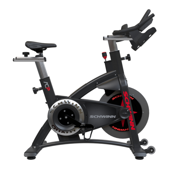
Schwinn AC Power Service Manual
Indoor cycling bike
Hide thumbs
Also See for AC Power:
- Owner's manual (16 pages) ,
- Assembly manual (7 pages) ,
- Service manual (17 pages)
Table of Contents
Advertisement
Advertisement
Table of Contents

Subscribe to Our Youtube Channel
Related Manuals for Schwinn AC Power


Summary of Contents for Schwinn AC Power
- Page 1 Core Health & Fitness Schwinn® AC Power SERVICE MANUAL...
-
Page 2: Table Of Contents
TABLE OF CONTENTS Click any text to jump to section PRODUCT SPOTLIGHT ............................. 3 OTHER MANUALS ............................. 4 ACCESSORIES ............................. 5 ..................5 Cranks & Pedals ..................6 Alternate Handlebars ..................6 Dumbbell Holder REPLACEMENT PROCEDURES ............................. 7 ..................7 Shroud Removal Belt Tension .................. - Page 3 PRODUCT SPOTLIGHT 9-7300 A.C.™ Power 9-7370 A.C.™ Power Custom Overall Weight Width Length Height User Weight 120 lbs (54 kg) 21” (53 cm) 55” (140 cm) 46” (117 cm) 0-350 lbs (0-159 kgs) Product Conformity • EN957-1 (S,H) • EN957-10 (S,H) •...
- Page 4 AC Performance (100175) AC Performance (9-7320) AC Performance Plus AC Sport SC Power IC Classic AC Power Related Installation Manuals • MYE PVS Brackets Installation Consoles For troubleshooting regarding the consoles available for this bike, chose from one of the service...
-
Page 5: Cranks & Pedals
ACCESSORIES Standard Schwinn pedals have threaded shafts that connect to the crank arms. The right pedal is right-hand threaded while the left pedal is reverse threaded, meaning you turn to the left to tight- en and right to loosen. For pictures of all different Schwinn pedals, see document... -
Page 6: Alternate Handlebars
Alternate Handlebars 718-5932 Studio Handlebar 000-0048 000-0048 718-5932 718-5932 Dumbbell Holder 718-5957 Dumbbell Holder Page 6... -
Page 7: Shroud Removal
REPLACEMENT PROCEDURES Shroud Removal Use a #2 phillips screwdriver to remove the screw securing the right side flywheel cap to the bike, then remove the cap. Use a #2 phillips screwdriver to remove the screws securing the left generator cover to the bike With the left generator cover removed, use a screwdriver to remove the screw hidden by the generator board, angled as shown. - Page 8 Remove the outer chainguard. TECH TIP: Slowly rotate the user right side crank arm toward the rear of the bike to help with removal of the outer chain- guard. Optional Step Remove the inner drive cover only if replacement is need- Page 8...
-
Page 9: Belt Tension
Belt Tension Use a 9/16” socket to loosen the axle nuts on both sides of the flywheel. Remove the tension bolt covers from the front of the bike Use a 10mm deep socket to tension/loosen the left and right tension nuts by turning clockwise to tighten and counter-clockwise to loosen. -
Page 10: Belt Replacement
Belt Replacement Use a #2 phillips screwdriver to remove the screw securing the right side flywheel cap to the bike, then remove the cap. Use a #2 phillips screwdriver to remove the screws securing the left generator cover to the bike With the left generator cover removed, use a screwdriver to remove the screw hidden by the generator board, angled as shown. - Page 11 Remove the outer chainguard. TECH TIP: Slowly rotate the user right side crank arm toward the rear of the bike to help with removal of the outer chain- guard. Use a 9/16” socket to remove the axle nuts on both sides of the flywheel.
- Page 12 Carefully move the flywheel toward the rear of the bike and down to drop the flywheel free from the frame. Remove the old belt from the front and rear sprockets, replace if needed or if belt is worn Optional Step Replace the flywheel Loop one end of the belt around the front sprocket located on the flywheel.
- Page 13 Lower the brake down and ensure that none of the brake magnets are touching the flywheel. Brake Magnets Once the belt has been tensioned so that the correct Hz is Flywheel measured and the flywheel has been checked for align- ment then tighten the axle bolts that were loosened in Step NOTE: Part of the frame has been moved for clarity Appx.
- Page 14 Pedal Replacement (Threaded) Use a 9/16” open-ended wrench to remove the pedal. Turn counter-clockwise to remove the user right pedal, turn clockwise to remove the left pedal. NOTE: The crank arm and pedal are shown detached from the bike for clarity only, it is not necessary to remove the crank arm.
- Page 15 Pedal Replacement (Morse Taper) Use an 8mm allen key to remove the pedal bolt. NOTE: The crank arm and pedal are shown detached from the bike for clarity only, it is not necessary to remove the crank arm. Thread a crank puller tool with the smaller 11mm tip into the crank arm, then use the tool to push the pedal out of the crank arm.
- Page 16 Adjusting Leveling Feet Ensure the bike is level by adjusting all four leveling feet. Turn the leveling foot clockwise to lower the bike and counter-clockwise to raise the bike. When leveled properly, the bike should not wobble or lean to any one side. Page 16...
- Page 17 Crank Arm Replacement Use a #2 phillips screwdriver to remove the screw securing the right side flywheel cap to the bike, then remove the cap. Use a #2 phillips screwdriver to remove the screws securing the left generator cover to the bike With the left generator cover removed, use a screwdriver to remove the screw hidden by the generator board, angled as shown.
- Page 18 Remove the outer chainguard. TECH TIP: Slowly rotate the user right side crank arm toward the rear of the bike to help with removal of the outer chain- guard. Walk the belt/chain off of the bike unless replacing the user left side crank arm only.
- Page 19 Install the user right crank arm by aligning the splines in the crank arm (blue) to the bottom bracket shaft (yellow). Use a dead blow hammer to pull the arm as close to the inner race as possible With the user right crank arm in the 6 o’clock position, install the user left crank arm in the 12 o’clock position.
- Page 20 4iiii Crank Replacement Use an 8mm allen key to remove the crank bolt. Thread a crank puller tool with the larger 16.5mm tip into the crank arm, then use the tool to pull the crank arm off the bottom bracket. Ensure the opposite side crank arm is at the 12 o’clock position then push the new crank arm onto the bottom bracket at the 6 o’clock position.
- Page 21 Install the pedal into the crank arm then use a torque wrench and a 8mm allen socket to torque to the pedal bolt according to the specifications below: • Threaded Pedal: 25-30 ft-lb (34-40 Nm) • Morse Taper Pedal: 33 -37 ft-lb (45-50 Nm) NOTE: The pedal MUST be torqued to the above specifications otherwise a failure of the pedal may occur.
-
Page 22: Pairing & Calibrating The 4Iiii Crank
Pairing and Calibrating the 4iiii Crank Press and hold “STAGE” and “AVG/MAX” for 3-5 seconds to access the service menu. Use “AVG/MAX” to scroll until “SENSOR TYPE” is displayed then push the backlight button to access the sensor menu. Ensure that “4iiii” is displayed as the sensor type. If the sensor type is set to “Echelon 2”... -
Page 23: Bottom Bracket Replacement
Bottom Bracket Replacement Use a #2 phillips screwdriver to remove the screw securing the right side flywheel cap to the bike, then remove the cap. Use a #2 phillips screwdriver to remove the screws securing the left generator cover to the bike With the left generator cover removed, use a screwdriver to remove the screw hidden by the generator board, angled as shown. - Page 24 Remove the outer chainguard. TECH TIP: Slowly rotate the user right side crank arm toward the rear of the bike to help with removal of the outer chain- guard. Use a 9/16” socket to loosen the axle nuts on both sides of the flywheel.
- Page 25 Use a 8mm hex key to remove both the right (shown) and left side crank arm bolts. Thread a crank puller tool with the larger 16.5mm tip into the crank arm, then use the tool to pull the crank arm off the bottom bracket.
- Page 26 After removing the bottom bracket, spray a cutting oil solvent (simple green or comparable) on the threads. Use a wire brush and clean the bottom bracket threads. CLEAN Note: Use wire brush in a clockwise/counterclockwise motion only. Do not brush across the threads. Wipe the threads clean and allow 10-15 minutes for the surface to dry.
- Page 27 With the user right crank arm in the 6 o’clock position, install the user left crank arm in the 12 o’clock position. Aligning the splines to the bottom bracket shaft, use a dead blow hammer to pull the arm as close to the inner race as possible Use a torque wrench coupled with an 8mm allen socket to reinstall the crank bolt and torque to the value below:...
- Page 28 Brake Rod Replacement Use a #2 phillips screwdriver to remove the screws secur- ing the right side sweatguard to the bike. Use a small punch or screwdriver to press the brake rod cap locking tabs in from both the left and right sides of the frame, then pull upwards on the brake rop cap.
- Page 29 Use a 27mm open-ended wrench to remove the brake rod assembly while turning clockwise to disconnect the brake rod assembly from the brake adjustment nut Page 29...
- Page 30 Brake Replacement Use a #2 phillips screwdriver to remove the screws securing the right side sweatguard to the bike. Use a small punch or screwdriver to press the brake rod cap locking tabs in from both the left and right sides of the frame, then pull upwards on the brake rod cap.
- Page 31 Remove the Brake Assembly from the bike: Use a 3mm allen key to loosen the brake bolt lock screw (blue). Using a pair of needle nose pliers, carefully disconnect the brake spring from the frame (green). Using a 16mm open-ended wrench and a 16mm socket, Spring remove the brake bolt (yellow), then remove the brake assembly.
- Page 32 Press and hold STAGE and “AVG/MAX” for 3-5 seconds to access the service menu. Once in the service menu, use the AVG/MAX button to scroll to the CALIBRATE menu. Press and release the LIGHT button to enter the menu. Scroll to CALIBRATE ZEROPOINT option and press the LIGHT button.
- Page 33 The console will display that the Zeropoint is now set. Press the LIGHT button to exit CALIBRATE ZEROPOINT. Once the calibration passes, go to CALIBRATE CURRENT ANGLE and verify the angle is 0.0 (+/- 0.1 degrees). Occa- sionally, the calibration process does not correctly set the angle on the first try.
-
Page 34: Other Replacement Procedures
Other Replacement Procedures Procedure Link Note Replacing the battery on an AC Power 637-8578 Replacing the generator belt 637-8642 Page 34... -
Page 35: Power & Mechanical Issues
TROUBLESHOOTING This page lists out all procedures available for Schwinn bikes. Use the icon to open the procedure in a new browser window. Internet connection is required. Power & Mechanical Issues Link Note Procedure No power on an Echelon 2G... - Page 36 © 2018 CORE HEALTH & FITNESS, LLC PART NUMBER 637-8648, REV A...
Need help?
Do you have a question about the AC Power and is the answer not in the manual?
Questions and answers