
Related Manuals for Champion 71001I


Summary of Contents for Champion 71001I
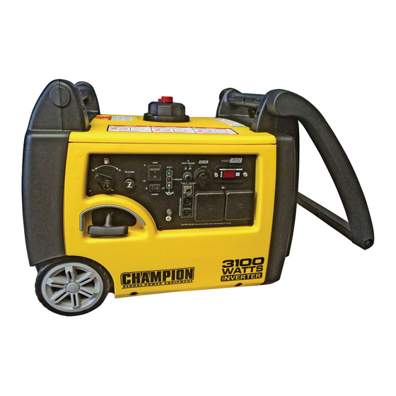
- Page 1 OWNER’S MANUAL & OPERATING INSTRUCTIONS PORTABLE INVERTER GENERATOR This manual covers the following models: 71001I (EU) / 72301 (EU) / 73001I (EU) 73001I-P (EU) SAVE THESE INSTRUCTIONS Important Safety Instructions are included in this manual.
-
Page 2: Manual Conventions
WARNING indicates a potentially hazardous help. Please contact your local dealer. situation which, if not avoided, could result in death or serious injury. Champion Power Equipment Support CAUTION CAUTION indicates a potentially hazardous situation which, if not avoided, may result in minor Model Number or moderate injury. -
Page 3: Safety Rules
SAfETy RULES SAfETy RULES WARNING dANGER dANGER WARNING Generator produces powerful voltage. Fuel and fuel vapours are highly flammable and Rapid retraction of the starter cord will pull hand and Read this manual thoroughly before operating your extremely explosive. Unintentional start up can arm towards the engine faster than you can let go generator. - Page 4 ASSEMBLy ASSEMBLy Add Engine Oil Add Engine Oil Cont’d. Your generator requires some assembly. This unit ships Connecting the Battery Cont’d. from our factory without oil. It must be properly serviced CAUTION Degrees Celsiusº (Outside) NOTE with fuel and oil before operation. If you have any questions regarding the assembly of your If the battery cables are not visible once the battery DO NOT attempt to crank or start the engine before it...
-
Page 5: Operation
ASSEMBLy OPERATION Add fuel Add fuel Cont’d. Generator Location Grounding Never operate the generator inside any building! (See Use clean, fresh, regular unleaded fuel with a The generator system ground connects the frame to the NOTE safety warnings section). In some areas generators must ground terminals on the power panel. -
Page 6: Economy Control Switch
OPERATION OPERATION Manual Choke Start Manual Choke Start Cont’d. Electric (Optional) and Recoil Start Recoil Start - Alternate Model for the 73001i-P only. Make certain the generator is on a flat, level surface. Make certain the generator is on a flat, level surface. If the battery is dead or not able to produce enough NOTE Disconnect all electrical loads from the generator. - Page 7 OPERATION OPERATION do Not Overload Generator Operation at High Altitude Connecting Electrical Loads 12V dC Outlet Be aware that engine efficiency can reduce and exhaust Let the engine stabilize and warm up for a few Capacity The 12V DC outlet can be used with the supplied emissions increase when working at high altitude.
-
Page 8: Maintenance And Storage
MAINTENANCE & STORAGE MAINTENANCE ANd STORAGE The owner/operator is responsible for all periodic Oil Cont’d. Generator Maintenance Cont’d. Charge the Battery maintenance. For a generator equipped with batteries for electric Use a damp cloth to clean exterior surfaces of the generator. WARNING NOTE starting, proper battery maintenance and storage should... -
Page 9: Troubleshooting
TROUBLESHOOTING CONTROLS ANd fEATURES Wireless Remote Control Problem Cause Solution This generator is equipped with a wireless remote Generator will not start No fuel Add fuel control system for starting and stopping. The system Faulty spark plug Replace spark plug consists of (4) main components: Unit loaded during start up Remove load from unit... -
Page 10: Parallel Operation
Wireless Set Button Parallel Operation SPECIFICATIONS 71001i-EU 72301i-EU Two (2) Champion model 100261 generators can The wireless set button is a feature that lets the user Gasoline Starting Watts 1000W 2300W sync remotes to the generator. One can set up to two... -
Page 11: Technical Diagrams
DC Operation Voltmeter Voltmeter Automatic Voltage Regulation Automatic Voltage Regulation Battery Battery Start Type Recoil Start Type Recoil/Electric Start/Wireless Remote Engine Brand Champion Engine Brand Champion Engine Size Engine Size 171cc 171cc Engine Type 4-stroke Engine Type 4-stroke Engine Speed... - Page 12 TECHNICAL dIAGRAMS TECHNICAL dIAGRAMS 71001i 71001I (EU) PARTS dIAGRAM 71001I (EU) PARTS LIST...
- Page 13 TECHNICAL dIAGRAMS TECHNICAL dIAGRAMS 71001i 71001I (EU) PARTS dIAGRAM 71001I (EU) PARTS LIST...
- Page 14 TECHNICAL dIAGRAMS TECHNICAL dIAGRAMS 72301i 72301i 72301I (EU) PARTS dIAGRAM 72301I (EU) PARTS LIST...
- Page 15 TECHNICAL dIAGRAMS TECHNICAL dIAGRAMS 72301i 72301i 72301I (EU) PARTS dIAGRAM 72301I (EU) PARTS LIST...
- Page 16 TECHNICAL dIAGRAMS TECHNICAL dIAGRAMS 73001I (EU) PARTS dIAGRAM 73001I (EU) PARTS LIST No Part Number Description No Part Number Description 1.9074.4.0516.1 Screw/Washer Assembly M5×16, Black 67 83.201600.01 Supporter, Right 2.08.052.1 Bolt M6 x 16, Black 68 83.201200.01 Motor Mount 83.200200.01.2 Cover, Left, Black 69 83.200607.01 Plug, Oil Drain Hole...
- Page 17 73001i-P-EU TECHNICAL dIAGRAMS TECHNICAL dIAGRAMS 73001I-P (EU) PARTS dIAGRAM 73001I-P (EU) PARTS LIST 73001i-P-EU...
- Page 18 73001i-P-EU TECHNICAL dIAGRAMS TECHNICAL dIAGRAMS 73001i-P-EU 73001I-P (EU) PARTS dIAGRAM 73001I-P (EU) PARTS LIST...
- Page 19 71001i TECHNICAL dIAGRAMS TECHNICAL dIAGRAMS 72301i 71001I (EU) WIRING dIAGRAM 72301I (EU) WIRING dIAGRAM...
- Page 20 TECHNICAL dIAGRAMS TECHNICAL dIAGRAMS 73001i-P-EU 73001I (EU) WIRING dIAGRAM 73001I-P (EU) WIRING dIAGRAM...
Need help?
Do you have a question about the 71001I and is the answer not in the manual?
Questions and answers