
Related Manuals for JUMO Wtrans B


Summary of Contents for JUMO Wtrans B
- Page 1 JUMO Wtrans B Programmable head transmitter with wireless data transmission Operating Manual 70706000T90Z001K000 V1.01/EN/00536757...
-
Page 3: Table Of Contents
Contents Contents Introduction ........... . 5 Safety information . - Page 4 Contents Setup program..........29 General information about the setup program .
-
Page 5: Introduction
Introduction 1 Introduction Safety information General This manual contains information that must be observed in the interest of your own safety and to avoid material damage. This information is supported by symbols which are used in this manual as indicated. Please read this manual before starting up the device. -
Page 6: Description
1 Introduction Description The Wtrans B head transmitter with wireless data transmission is used in conjunction with a Wtrans re- ceiver for stationary or mobile acquisition of temperatures with RTD temperature probes or thermocou- ples. Alternatively, resistances of up to 10 kΩ or voltages of up to 50 mV and up to 20 mA using external shunt currents can be measured. -
Page 7: Connection Elements And Connectors
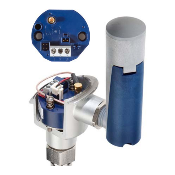
1 Introduction Connection elements and connectors (10) (11) SMB antenna connector (antenna connection) Voltage supply connector (battery connection) Cable guide for antenna cable and voltage supply Sensor connection Setup connector Fastening holes for installation in the terminal head, form B Voltage supply socket (battery connection) SMB antenna socket (antenna connection) Seal... -
Page 8: Dimensions
1 Introduction Dimensions 1.5.1 Transmitter Ø44 1.5.2 Antenna-battery housing Ø30 approx. 105 approx. 125 49.5... -
Page 9: Declaration Of Conformity
Declaration of conformity NOTE! Hereby JUMO GmbH & Co. KG declares that the radio equipment type Wtrans is in compliance with Di- rective 2014/53/EU. The full text of the EU declaration of conformity is available at the following Internet address: www.jumo.net... - Page 10 1 Introduction...
-
Page 11: Identifying The Device Version
Identifying the device version 2 Identifying the device version Nameplate Position The rating plate is glued laterally to the transmitter. The factory set transmitter ID is additionally stated on a sign fitted on top of the transmitter. Contents The nameplate contains important information. This includes: Description Designation on the nameplate Example... -
Page 12: Order Details
2 Identifying the device version Order details Basic type 707060 JUMO Wtrans B Programmable head transmitter with wireless data transmission Input Standard with default settings Customer-specific programming according to specifications Output (transmitter) Radio frequency 868.4 MHz (Europe) Extra code None The terminal head form B is not included in the scope of delivery. -
Page 13: Preparing The Transmitter
Preparing the transmitter 3 Preparing the transmitter Inserting/changing the battery CAUTION! Make sure that pollutants, moisture, and steam cannot enter the device. The device could be destroyed. When inserting/changing the lithium battery, make sure that the device is not exposed to contami- nants, moisture, or steam. - Page 14 3 Preparing the transmitter If the battery was removed or if it must be replaced, proceed as follows: 1. Undo the battery lid screw (A) on the antenna-battery housing and open the housing lid (B). 2. Press on the battery in the area of the minus pole (D) to remove the battery (C). 3.
-
Page 15: Safety Information Concerning Lithium Batteries
3 Preparing the transmitter Safety information concerning lithium batteries http://battery.jumo.info Battery operating life The battery service life, depending on the transmission interval (2 s, 15 s, 30 s, 90 s) and the ambient temperature, are shown in the following figure. - Page 16 3 Preparing the transmitter...
-
Page 17: Transmission Range
Transmission range 4 Transmission range General information about wireless transmission Wireless signals are electromagnetic waves, the signal of which weakens during travel from the trans- mitter to the receiver (this is referred to as path attenuation). The field strength drops inversely propor- tionally to the square of the distance between the transmitter and receiver. -
Page 18: Possible Impairment Of Radio Transmission
4 Transmission range Possible impairment of radio transmission Collisions in case of too many transmitters When using a large number of transmitters, do not select a transmission interval that is too low, otherwise the radio channel will be unnecessarily occupied. A transmission interval that is too low leads to a very high data volume on the selected frequency, which can lead to collisions with other transmitters. - Page 19 4 Transmission range For this reason, we recommend using a maximum of 16 transmitters for the smallest transmission inter- val of 1 s. For the factory setting of 15 s, a considerably larger number of transmitters can be used. Estimating the maximum number of transmitters If more than the recommended 16 transmitters are to be used with a transmission interval of 1 s, select a higher transmission interval to prevent an increased error quota.
- Page 20 4 Transmission range...
-
Page 21: Mounting
Mounting 5 Mounting Information about fastening, mounting, and arrangement NOTE! Install the antenna-battery housing vertically to the top and, if possible, with free view to the receiver an- tenna. NOTE! Never cover or coat the antenna-battery housing with metallic objects. Otherwise, the transmitter range is impaired. -
Page 22: Installing The Antenna-Battery Housing
5 Mounting Installing the antenna-battery housing Proceed as follows to install the antenna-battery housing: 1. Route the voltage supply socket (B) and SMB antenna socket (C) of the antenna-battery housing (A) through the opening (G) of the connection head (H). 2. -
Page 23: Installing The Transmitter
5 Mounting Installing the transmitter Proceed as follows to install the transmitter: 1. Let all connection cables hang out of the terminal head. 2. Insert the transmitter (A) into the terminal head (D). 3. Fit the transmitter (A) in the terminal head (D) using the screws and pressure springs (included in the delivery scope). -
Page 24: Aligning The Antenna
5 Mounting Aligning the antenna The recommended and unfavorable antenna alignment possibilities are shown in the following figure. The best possible reception is ensured when the recommended alignment possibilities are used. Recommended installation: Connection head vertical and antenna-battery housing vertical to the top Recommended installation: Connection head horizontal and antenna-battery housing vertical to the top... -
Page 25: Electrical Connection
Electrical connection 6 Electrical connection Safety information • The electrical connection must only be carried out by qualified personnel. • When installing and operating the transmitter ensure that no electro-static charging can take place. • The transmitter is not suitable for installation and application areas with an explosion hazard. •... -
Page 26: Connection Diagram
6 Electrical connection Connection diagram 6.3.1 Voltage supply Connection Con- Terminals Symbol and terminal designation nector Lithium battery, DC 3.6 V 6.3.2 Analog input Connection Con- Terminals Symbol and terminal designation nector RTD temperature probe 1 and 3 2-wire circuit RTD temperature probe 1 to 3 3-wire circuit... -
Page 27: Output
6 Electrical connection 6.3.3 Output Connection Con- Terminals Symbol and terminal designation nector Antenna connector 6.3.4 Interface Connection Con- Terminals Symbol and terminal designation nector Setup... - Page 28 6 Electrical connection...
-
Page 29: Setup Program
Setup program 7 Setup program General information about the setup program The setup program serves to configure transmitters and receivers by means of a PC. The configuration data can be archived on data carriers and printed. Configurable parameters include: • Transmitter detection (transmitter ID) •... -
Page 30: Establishing The Connection Between Pc And Transmitter
7 Setup program Establishing the connection between PC and transmitter The connection between transmitter and PC is established via a PC interface TTL/RS232 converter and adapter (socket) or USB/TTL converter and adapter (socket). CAUTION! Permanent interface operation! The PC interface TTL/RS232 converter or USB/TTL converter is only designed for a time-limited inter- face connection. - Page 31 7 Setup program TTL/RS232 Laptop/PC Adapter socket, 4-pin RS232 connector Transmitter interface For the setup via the TTL/RS232 converter, establish the following connections: 1. Insert the RS232 connector (2) into the laptop/PC (1). 2. Connect the adapter socket, 4-pin, (3) to the transmitter interface (4). NOTE! For the transmitter configuration, ensure that the transmitter is connected to the voltage supply of the antenna-battery housing.
- Page 32 7 Setup program USB/TTL USB/TTL Laptop/PC USB connector USB socket USB/TTL converter Modular jack RJ-45 Modular line adapter Adapter socket, 4-pin Transmitter interface For the setup via the USB/TTL converter, establish the following connections: 1. Insert the USB connector (2) of the USB cable into the laptop/PC (1). 2.
-
Page 33: Transmitter Configuration
7 Setup program Transmitter configuration This chapter explains the configuration of a transmitter via the setup program. Prerequisite being that the transmitter and the PC are connected via an interface. 7.4.1 Establishing the communication A differentiation is made between two different way of proceeding when establishing the communication between transmitter and setup program: •... -
Page 34: Reading The Current Transmitter Parameters
7 Setup program 7.4.2 Reading the current transmitter parameters How to proceed: 1. In the "File" menu select the "New" function. The "Device assistant” starts. 2. Confirm the "User-defined setting" by pressing the "Continue" button. 3. Select the "Frequency band" and confirm with "Continue". 4. -
Page 35: Parameter Overview
7 Setup program Parameter overview Parameter Factory setting Value range/selection Transmitter ID Deactivated 1 to 99999 (Transmitter ID) Transmission interval 15 s 1 to 3600 s Radio frequency 868.4 MHz Display only, cannot be edited Sensor type RTD temperature RTD temperature probes, probes Thermocouple,... - Page 36 7 Setup program Term definition Transmitter ID The transmitter ID is an unmistakable ID with max. 5 characters which is recognized by the receiver. The ID can be individually changed, for example, to achieve a better overview of a system. Ensure that an ID is not used simultanously by two transmitters within the reception range to avoid malfunctions.
-
Page 37: Technical Data
Technical data 8 Technical data Analog input RTD temperature probe Designation Standard Measuring range Measuring accuracy Pt100 DIN EN 60751 -100 to +200 °C ±0.1 K (TK value = 3.85 × 10 1/K) -200 to +600 °C ±0.2 K Pt500 DIN EN 60751 -100 to +200 °C ±0.1 K... - Page 38 8 Technical data Thermocouples Designation Standard Measuring range Measuring accuracy Fe-CuNi "L" DIN 43710 -200 to +900 °C ±0.1 % Fe-CuNi "J" DIN EN 60584 -210 to +1200 °C ±0.1 % from -100 °C Cu-CuNi "U" DIN 43710 -200 to +600 °C ±0.1 % from -100 °C Cu-CuNi "T"...
-
Page 39: Output (Radio Transmission)
8 Technical data Voltage Designation Measuring range Measuring accuracy Voltage 0 to 50 mV ±0.1 % All accuracy values in % refer to the maximum measuring range. Measuring circuit monitoring Measuring probe Out of range Probe/cable Wire break detection short circuit detection detection Thermocouple Yes/Yes... -
Page 40: Environmental Influences
8 Technical data Environmental influences Transmitter in the terminal head, form B with antenna-battery housing Ambient temperature range -30 to +85 °C -40 to +85 °C; rel. humidity ≤ 95 % Storage temperature range; stor- age humidity Temperature influence Thermocouple ≤... - Page 41 8 Technical data Antenna battery housing Type Plastic housing with M20 × 1.5 thread for terminal head, form B Material Polyetherimide Flammability class UL 94 HB or UL 94 V-0 Dimensions Diameter 30 mm Height 115 mm Protection type IP65, according to DIN EN 60529 Connection SMB inlet, 50 Ω...
- Page 42 8 Technical data...
-
Page 43: China Rohs
China RoHS 9 China RoHS... - Page 44 9 China RoHS...
- Page 48 JUMO GmbH & Co. KG JUMO Instrument Co. Ltd. JUMO Process Control, Inc. Street address: JUMO House 6733 Myers Road Moritz-Juchheim-Straße 1 Temple Bank, Riverway East Syracuse, NY 13057, USA 36039 Fulda, Germany Harlow, Essex CM 20 2DY, UK Delivery address:...
Need help?
Do you have a question about the Wtrans B and is the answer not in the manual?
Questions and answers