Table of Contents
Advertisement
Quick Links
Instruction Manual
Model 8800 series
GeoNet Wireless
No part of this instruction manual may be reproduced, by any means, without the written consent of Geokon, Inc.
The information contained herein is believed to be accurate and reliable. However, Geokon, Inc. assumes no responsibility
for errors, omissions or misinterpretation. The information herein is subject to change without notification.
Copyright © 2014-2018 by Geokon, Inc.
(Doc Rev N, 11/14/2018)
Advertisement
Table of Contents
Troubleshooting

Related Manuals for Geokon 8800-2-1A


Summary of Contents for Geokon 8800-2-1A
- Page 1 Model 8800 series GeoNet Wireless No part of this instruction manual may be reproduced, by any means, without the written consent of Geokon, Inc. The information contained herein is believed to be accurate and reliable. However, Geokon, Inc. assumes no responsibility for errors, omissions or misinterpretation.
- Page 3 Upon examination by Geokon, if the unit is found to be defective, it will be repaired or replaced at no charge. However, the WARRANTY is VOID if the unit shows evidence of having been tampered with...
-
Page 4: Table Of Contents
TABLE of CONTENTS 1. INTRODUCTION ..............................1 1.1 S ..............................1 ENSOR 1.2 N ............................1 ETWORK UPERVISOR 1.3 N ..........................2 ETWORK ONSIDERATIONS 2. NETWORK INSTALLATION..........................4 2.1 I ..............................4 TEMS EEDED 2.2 C ..........................4 HANNEL ONFIGURATION 2.3 C ............................ - Page 5 APPENDIX B. MODELS ............................25 B.1 S ..............................25 UPERVISOR B.1.1 RS-232 (8800-2-1_ and 8800-4-1_) ......................25 B.1.2 USB (8800-2-2_ and 8800-4-2_) ......................25 B.2 N ................................25 B.2.1 Gland Seal (8800-1-1_ and 8800-3-1_)....................25 B.2.2 Bulkhead (8800-1-2_ and 8800-3-2_) ...................... 26 B.3 M ..............................
- Page 6 FIGURES 1 - S ..........................1 IGURE INGLE HANNEL 2 - N ..........................1 IGURE ETWORK UPERVISOR 3 - C ......................2 IGURE LUSTER ETWORK OPOLOGY 4 - W ......................2 IGURE ORKING ROUND BSTRUCTIONS 5 - F ............................. 3 IGURE RESNEL 6 - C...
-
Page 7: Introduction
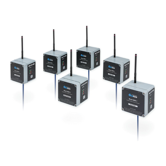
1.1 Sensor Node Sensor Nodes collect battery and temperature data and will read any of Geokon’s vibrating wire sensors. Each Node can read one sensor by itself, or up to eight sensors when connected to a GeoNet Multiplexer. Nodes ship with the following accessories: •... -
Page 8: Network Considerations
1.3 Network Considerations GeoNet uses network technology that is self-configuring and self-healing. Data from the Nodes is either sent directly to the Supervisor, or it arrives via communication between the Nodes. This effectively creates a cluster tree topology. Figure 3 illustrates this concept. Figure 3 - Cluster Tree Network Topology Each transmission from Node to Supervisor or Node to Node is considered one “hop”. -
Page 9: Figure 5 - Fresnel Zone
For optimum performance, Geokon recommends creating as much vertical space as possible between the straight-line path and obstacles, including the ground. Figure 5 illustrates what is known as the Fresnel zone. -
Page 10: Network Installation
2. NETWORK INSTALLATION 2.1 Items Needed To install a network, begin with the Supervisor and at least one Node that is within radio range of the Supervisor. 2.2 Channel Configuration Channels allow multiple networks to coexist in the same area. All devices are set to communicate on channel one from the factory and do not need to be altered if operating a single network in a given area. -
Page 11: Connecting Sensors
2.3 Connecting Sensors A sensor may be attached to a Node before or after the Node has been powered on. 2.3.1 Cable Gland Models (8800-1-1_) To wire a sensor on models featuring a cable gland: 1) Open the device by unscrewing the four captive screws on the front of the enclosure. Make sure that no dirt, water or other contaminants are allowed to enter the enclosure. -
Page 12: Battery Installation
2.5 Battery Installation Install the D cells in the Supervisor first, followed by the Nodes. Install the batteries as follows: 1) Open the device by unscrewing the four captive screws on the front of the enclosure. Make sure that no dirt, water or other contaminants are allowed to enter the enclosure. 2) Prior to installing the D cells, ensure that the battery select switch is set to the “OFF”... -
Page 13: Accessories
2.6 Accessories After the batteries have been installed: 1) Remove the desiccant packs from the plastic seal top bag they were shipped in and place them inside the enclosure. 2) Reinstall the cover. Ensure that the rubber gasket clean and properly seated in the groove on the underside of the cover. -
Page 14: Status Button Functionality
The default time a network will remain in deployment mode is one hour. When a new Node joins the network the timer will reset, extending the deployment period for another hour. If more time is needed while deploying Nodes, the default deployment timeout may be changed using Agent software. -
Page 15: Node
Changes initiated by the status button will be made on the following radio cycle. This could take up to three minutes when switching from normal mode to deployment mode, as changes to the radio settings can only occur when all the radios in the network are awake. -
Page 16: Figure 12 - Button Logic
Figure 12 - Button Logic (Node) -
Page 17: Geonet Multiplexer
3. GEONET MULTIPLEXER The GeoNet Multiplexer expands the number of vibrating wire sensors a Node can read from one to eight. Channel switching is controlled by the Node and is accomplished by solid-state (nonmechanical) circuitry. Each Node with a Multiplexer attached uses the equivalent data of four single nodes. Since the maximum number of Nodes per Network is 100, the maximum amount of Nodes with a Multiplexer attached that may be connected to a single network is 25. -
Page 18: Lightning Protection
3.1.2 Lightning Protection Each VW (Vibrating Wire) channel is protected by a 230V gas discharge tube, followed by a high-speed protector and a transient voltage suppression diode. Each TH (Thermistor) channel is protected by a 230V gas discharge tube, followed by an inductor (lower resistance than high-speed protectors) and a transient voltage suppression diode. -
Page 19: Determining Correct Wiring
Tighten the screws a little at a time, working in a diagonal pattern; this ensures that the cover seals correctly. 3.3.3 Determining Correct Wiring Geokon instruments with a single vibrating wire gage should be wired according to Table 4. (As shown on channels six, seven, and eight in Figure 14.) Position... -
Page 20: Shared Channels
3.4 Shared Channels Some Geokon instruments utilize multiple gages that share a single conductor for negative polarity. During normal operation, each channel of the Multiplexer consists of four signals, which are all switched together: VW+, VW-, TH+, and TH-. However, the Multiplexer can be configured to switch the VW- signal separately from the rest, allowing for configurations where multiple gages share one common VW- signal. -
Page 21: Geonet Addressable Sensor Nodes
4. GEONET ADDRESSABLE SENSOR NODES Model 8800-5 and 8800-6 GeoNet Addressable Sensor Nodes are used to communicate with 6150E Addressable MEMS strings (Figure 16). Figure 16 - 6150E Addressable MEMS and Addressable Sensor Node Addressable Sensor Nodes function in the same manner as other Nodes, and can be installed using the previous sections in the manual. -
Page 22: Trouble Shooting
Node Connection Conductor Color Description 485+ White Communication RS-485+ 485- Green Communication RS-485- 12 volt power to the string Black Ground SHLD Bare Analog Ground (shields) Table 5 - Addressable Sensor Wiring Figure 17 - Addressable Sensor Node with 6150E Installed 4.2 Trouble Shooting Symptom: Node does not have power ... -
Page 23: Add On Modules For Supervisor Compatibility With Ether Net And Cellular Modems
5. ADD ON MODULES FOR SUPERVISOR COMPATIBILITY WITH ETHER NET AND CELLULAR MODEMS 5.1 Introduction Model 8800-2-4A (cellular modem compatibility) and Model 8800-2-4B (Ethernet compatibility) are add-on modules for the Network Supervisor to allow the end user to easily add remote communications and data download. -
Page 24: Setting Up The 8800-2-4B (Ethernet Add-On)
5.2.2 Setting up the 8800-2-4B (Ethernet Add-on) The MOXA 5110A will be setup by Geokon to communicate with a GeoNet Network Supervisor, however, the end user will need to finish the setup so that it works with their network. Configure an IP address by following the instructions below. (Note: The following steps should only be performed by your network administrator. -
Page 25: Figure 19 - Update Fields
6) Update the “IP Address”, “Netmask”, “Gateway”, and “DNS Server 1” fields to match your network. (Note: Do not make any other changes to the settings as it may affect proper communications to the GeoNet Network Supervisor.) Figure 19 – Update Fields 7) Click OK. -
Page 26: Maintenance
Supervisor. At a one-hour scan rate or higher, with only one hop, over 1,000 days of battery life can be expected. If greater battery life is needed, a 12-volt nominal input is available. Contact Geokon technical support for help utilizing this feature. Battery Life Estimates... -
Page 27: Replacing Batteries
6.3 Replacing Batteries Batteries should be replaced when the measured voltage of the D cells drops below 2.0 VDC or 11 volt for an external 12-volt battery. Units will cease operation at ~2.0 volts. When this occurs, a new set of batteries must be installed before the unit becomes operational again. (Refer to Section 2.5 for battery installation instructions.) In order for a Node to resume normal operation after replacing the batteries, it needs to synchronize with the network and acquire the network time. -
Page 28: Troubleshooting
Extending the sensor cable may enable moving the Node to a better location. If the signal does not improve, a higher gain directional antenna may be necessary. Contact Geokon for help. Symptom: Node will not synchronize with network... -
Page 29: Appendix A. Specifications
APPENDIX A. SPECIFICATIONS A.1 Device Specifications 8800-1 (Node) 8800-2 (Supervisor) Units Measurement Accuracy ±0.1% F.S. (400-5000 Hz) Data Memory Storage Capacity 1.44E+06 1.06E+06 Arrays Temperature Range -40 to +85 °C Thermistor Accuracy 2% F.S. °C Thermistor Resolution Communication Type USB/RS-232 Communication 115k,8-N-1 Communication Protocol... -
Page 30: 8800-8 Multiplexer Specifications
A.3 8800-8 Multiplexer Specifications GENERAL 2.8-3.6 VDC (regulated 3.3V provided by GeoNet Node) Power Requirements: Quiescent Current: 50uA Active Current: 1.5mA typical, 10mA MAX Operating Temperature: -30 ° to +85 °C MUX Cable Length: 10 ft. (max) Dimensions: 279.4 mm x 177.8 mm x 88.9 mm (11" x 7" x 3.5") ANALOG SWITCH Type: CMOS, Solid-state... -
Page 31: Appendix B. Models
B.1.1 RS-232 (8800-2-1_ and 8800-4-1_) Connects to a PC running the Agent program or other Modbus RTU master via an RS- 232 cable. Model # PC Connection Frequency Region 8800-2-1A RS-232 2.4 GHz North America 8800-2-1B RS-232 2.4 GHz International... -
Page 32: Bulkhead (8800-1-2_ And 8800-3-2_)
Model # Cable Connection Frequency Region 8800-1-1A Cable Gland 2.4 GHz North America 8800-1-1B Cable Gland 2.4 GHz International 8800-3-1A Cable Gland 900 MHz North America 8800-3-1B Cable Gland 900 MHz Brazil 8800-3-1C Cable Gland 900 MHz Australia Table 13 - Gland Seal Node Models B.2.2 Bulkhead (8800-1-2_ and 8800-3-2_) For use with sensor cables that have a male, 10-pin bulkhead connector attached. -
Page 33: Addressable Sensor Nodes
B.4 Addressable Sensor Nodes Addressable Sensor Nodes are used to read Addressable MEMS sensors. Model types are distinguished by radio output, as well as their sensor connection options. B.4.1 Gland Seal (8800-5-1_ and 8800-6-1_) For use with sensors cables with stripped and tinned ends. The sensor cable passes through an external cable gland and is wired into the terminal block according to Section 4.1. -
Page 34: Appendix C. Connector Pinouts
APPENDIX C. CONNECTOR PINOUTS C.1 Transducer Cable Connections C.1.1 Cable Gland, Models 8800-1-1_ and 8800-3-1_ Terminal Strip Description Cable Wire Color Position Vibrating Wire + Vibrating Wire - BLACK Thermistor + WHITE Thermistor - GREEN Analog Ground (shields) BARE WIRE Table 19 - Transducer Cable Connections (Gland Seal) C.1.2 10-Pin Bulkhead, Models 8800-1-2_ and 8800-3-2_ 10 Pin Bulkhead... -
Page 35: Appendix D. Modbus
APPENDIX D. MODBUS D.1 Protocol The Supervisor protocol is Modbus RTU. Information about Modbus can be found here: http://www.modbus.org/specs.php D.2 Supported Modbus Commands Modbus was originally developed for communicating with programmable logic controllers. Many Modbus commands do not make sense with respect to modern embedded devices. GeoNet Supervisors utilizes four commands: (0x03) Read Holding Registers (0x04) Read Input Registers... -
Page 36: Node Tables
Address (hex) Data Type 0xE00 Firmware Version uint16_t 0xE01 Hardware Version uint16_t 0xE02 Debug Version uint16_t 0xE09 Configuration bitfield 0xE0A Alarm Minutes uint16_t 0xE0B Minutes uint16_t 0xE0C Temp Command Code 0xE0D Channel uint16_t 0xE0E RTC Calibration uint16_t 0xE0F Serial Number LSW uint32_t 0xE11 Serial Number MSW... -
Page 37: Extended Memory
Data can be collected from the Node tables at a query interval equal to or less than the scan interval. Readings will appear in the Node tables as soon as they are successfully communicated from each Node to the Supervisor. The contents of channel zero through channel nine depends on the code at offset four (address 0xE95 in this example). -
Page 38: Figure 21 - External Flashr
Figure 21 - External Flash Read Flow Diagram Table 26 - Data Array Details (EXT Memory) -
Page 39: Conversions
D.8 Conversions The following equations can be used to obtain real numbers for the various sensors. D.8.1 Battery Voltage v=5* � � 16383 Raw = value from table v = volts D.8.2 Board Temperature mV=2.5* � � * 1000 16383 - �... -
Page 40: Data Types
D.9 Data Types uint8_t = unsigned 8 bit integer int8_t = signed 8 bit integer uint16_t = unsigned 16 bit integer int16_t = signed 16 bit integer uint32_t = unsigned 32 bit integer int32_t = signed 32 bit integer uint64_t = unsigned 64 bit integer int64_t = signed 64 bit integer IEEE-754 = single precision... -
Page 41: Appendix E. Sensemetrics Management Platform
APPENDIX E. SENSEMETRICS MANAGEMENT PLATFORM GeoNet Wireless nodes are compatible with the Sensemetrics sensor management platform. This combination of technologies greatly expands the ways in which data can be collected remotely, with “plug and play” connectivity and with the ability to be displayed in near real-time on a user- friendly, browser-based data platform. -
Page 42: Status Button
E.2 Status Button When the status button is pressed, nodes indicate their connection status with the network by briefly illuminating the LED indicators located above the status button. A red flash means the node has not yet discovered and joined the network. A green flash means the node has joined the network and is operating. -
Page 43: Appendix F. Firmware Upgrade
APPENDIX F. FIRMWARE UPGRADE F.1 Procedure To perform a firmware upgrade on a Node or Supervisor, complete the following: 1) Power off the unit by moving the battery select switch to the “OFF” position (Figure 24), or by disconnecting the external battery. (For units manufactured prior to June 2017, which do not have an OFF position, remove the D cells from the battery holder.) Figure 24 - Battery Selector Switch in OFF Position 2) Ensure that the unit is completely discharged of electrical potential by pressing the status... -
Page 44: Figure 26 - Upgrade Cabled
4) Connect the B8800-5 upgrade cable to the 8001-7 USB to RS-232 adapter cable, and then connect the 8001-7 USB to RS-232 cable to the computer. See Figure 26 for the completed set up. Figure 26 - Upgrade Cable Detail 5) Move all channel select dipswitches to the “On”... -
Page 45: Figure 28 - Update Progress
7) The green LED indicator on the right side of the unit will flash in one-second intervals. 8) Run the GeoNet Firmware Updater program. 9) Click “Select File” and choose the latest firmware file. (Firmware files are named in the following format: “GeoNet_Firmware_YYMMDD.txt”, where YY is the last two digits of the year, MM is the month, and DD is the day of the month.) 10) Using the drop down box below the “Select File”... -
Page 46: Troubleshooting
The B8800-5 multicolored upgrade ribbon cable must be used on all units with the exception of the RS-232 version supervisor. Updates should be done using the Geokon provided 8001-7 USB to RS232 adapter. Other adapters and native serial ports have been unreliable.
Need help?
Do you have a question about the 8800-2-1A and is the answer not in the manual?
Questions and answers