Table of Contents
Advertisement
Advertisement
Table of Contents
Troubleshooting

Related Manuals for DoAll C-4100NC


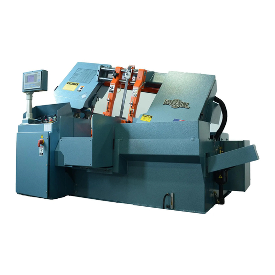
Summary of Contents for DoAll C-4100NC
- Page 1 C-4100NC Serial No: 524-97116 to 524-11322 524-13338 to Band Sawing Machine...
- Page 2 DAMAGE CLAIM PROCEDURES VISIBLE DAMAGE AT THE TIME OF DELIVERY: Note damage on carrier’s delivery receipt. Accept the shipment. It can be returned later if repairs are not possible in the field. Request a “damage inspection” from the delivery carrier: The carrier will send his own people or contract an independent agency to make the inspection.
- Page 3 For general information, visit our web site at: www.doallsawing.com DoALL SAWING PRODUCTS 2375B TOUHY AVENUE ELK GROVE, ILLINOIS 60007 U.S.A. The following registered trademarks of the DoALL Company are used in this manual: DoALL, Imperial Bi-Metal, Kleen-Kool, Polypac, Power-Cut and Tensigage. PB-482.5 (7-13) PRINTED IN U.S.A.
-
Page 4: Table Of Contents
TABLE OF CONTENTS MACHINE DIMENSIONS LUBRICATION Foot Pad Layout ........... 1 Lubrication Chart ..........32 Floor Plan (5 Foot Index Option) ......2 Lubrication Diagrams ..........33 Front View ............3 Side Views (Standard and 5 Foot Index Option) .. 4 MAINTENANCE MACHINE FEATURES Replacing Saw Guide and Back-Up Inserts .. -
Page 5: Machine Dimensions
MACHINE DIMENSIONS FOOT PAD LAYOUT... -
Page 6: Floor Plan (5 Foot Index Option)
MACHINE DIMENSIONS (Continued..) INCHES (± .03) MILLIMETERS (± 1 mm) FLOOR PLAN (5 Foot Index Option) -
Page 7: Front View
MACHINE DIMENSIONS (Continued..) INCHES (± .03) MILLIMETERS (± 1 mm) FRONT VIEW... -
Page 8: Side Views (Standard And 5 Foot Index Option)
MACHINE DIMENSIONS (Continued..) INCHES (± .03) MILLIMETERS (± 1 mm) SIDE VIEW (Standard) SIDE VIEW (5 Foot Index Option) -
Page 9: Machine Features
MACHINE FEATURES FRONT VIEW TOP VIEW... -
Page 10: Proximity Switch/Limit Switch Locations
MACHINE FEATURES (Continued..) PROXIMITY SWITCH/LIMIT SWITCH LOCATIONS Before machine number 218, limit switches (in parenthesis) were used instead of proximity switches. FRONT VIEW SIDE VIEW... -
Page 11: Installation
INSTALLATION LIFTING All the “left”, “right”, “front” and “rear” designations in this manual are as viewed by the operator facing the control console. NEVER lift the machine by its sawing head. Four (4) permanent eye holes are provided for LOCATION machine lifting purposes: (a) Two (2) lifting eyes are located at the rear of the index vise roller table;... -
Page 12: Electrical Installation
FLOOR INSTALLATION (Continued..) • The enclosure on the machine’s right rear side houses the band drive motor control. Place the level front to back on the fixed vise rails and adjust. Again, weight must bear evenly on all foot pads. The following are important dimensions to be obtained during leveling: •... -
Page 13: Preparation For Use
ELECTRICAL INSTALLATION (Continued..) Check the band drive transmission reservoir level gauge while the saw head is down. Capacity is approximately 18 quarts (17.0 liters). Electrical Connections to Disconnect Switch. Bring the power cable leads up to the disconnect Band Drive Transmission. switch. - Page 14 PREPARATION FOR USE (Continued..) If the hydraulic or band drive motor overloads open, the machine will shut down. Machine Start-Up Always use extreme care when handling saw bands. DO NOT attempt to remove the saw band cap while the band drive motor is running.
-
Page 15: Operation
USING THE JOB SELECTOR Job Selector recommendations are a general guide for correct power sawing on a prop- erly-maintained DoALL saw. They are based Refer to the Job Selector chart on the left bandwheel on cutting five (5) inch (127.0 mm) round,... -
Page 16: Control Console
CONTROL CONSOLE During manual or automatic mode: (a) If the saw • band is running and the fixed vise is clamped, the saw head will move down rapidly until the work Electrical Controls sensing arm contacts the material. The saw head continues moving down under Feed Force valve Band/Cycle Start. -
Page 17: Operator Workstation
CONTROL CONSOLE (Continued..) Hydraulic Controls Head Approach. This valve regulates the saw head’s descending rate. Turn the knob counterclockwise Lower the saw head completely when the to “increase” the velocity; clockwise to “decrease” hydraulic pump is to be shut down for an extended period of time (such as overnight). - Page 18 OPERATOR WORKSTATION (Continued..) Most screens have instructions on the screen to assist in entering information. Do not push two (2) or more buttons at the same time. Screens SCREENS (F1). When both the variable frequency drive disconnect and the control enclosure disconnects are "ON", push Hydraulic Start.
- Page 19 OPERATOR WORKSTATION (Continued..) Vise Control: Choices are STANDARD and • NESTING. The first time user is advised to use this screen STANDARD: Allows the operator to select to initially view the operation of the saw. “OVERLAP” or “NO OVERLAP” at the Vise Overlap option. The minimum butt end length is set to 2.50 inches (63.5 mm).
- Page 20 OPERATOR WORKSTATION (Continued..) A Fixed Vise Delay of .3 seconds is suggested for the first time user. • Vise Overlap: Choices are OVERLAP and NO OVERLAP. • Index Vise Delay. This allows time allotted for the index vise jaws to clamp before index movement OVERLAP: After the index has moved forward and is allowed (due to longer closing time resulting the fixed vise jaws clamp, a time lapses before the...
- Page 21 OPERATOR WORKSTATION (Continued..) • In the JOB SELECT area, using the "UP" or "DOWN" arrows keys, the operator should select the type of saw operation from three JOB HANDLING • Band speed range is 40 - 360 fpm (12 - 110m/ modes: SINGLE JOB, RUN LIST A and RUN LIST min).
- Page 22 OPERATOR WORKSTATION (Continued..) • If less than ten (10) jobs are entered in a list, a zero must be entered in the position following the last job entered in the list. For example, if RUN LIST A • Press the "UP" or "DOWN" arrow keys to view jobs is to contain eight (8) jobs, a zero must be entered in the library in groups of ten (10) or;...
- Page 23 OPERATOR WORKSTATION (Continued..) Job Screen Display (6 of 6) (F4) or Cut Time (F7). BAND SPEED (F5). (See F4-Screen 4) Pushing Job Screen Display (5 of 6) (F4). this button displays the band speed. Band speed may be changed by: (a) Entering a number; (b) If less than ten jobs are entered in a list, a zero Pushing the "UP"...
- Page 24 OPERATOR WORKSTATION (Continued..) FIXED CLAMP (F12). Push this button to clamp the fixed vise jaws during "MANUAL" operation (this function is latched on). The LED above the • A password must be entered to clear Jobs or Dones. button shines only when clamping force is applied. The password is the same as the model number of When the band drive motor is running, the fixed the saw (i.e.
-
Page 25: Other Controls
OPERATOR WORKSTATION (Continued..) HELP. This key is non-functional. CLEAR. Used to clear existing data. ENTER. Push this key to enter data. OTHER CONTROLS Variable Vise Pressure Controls The two Variable Vise Pressure control valves (positioned to the right of the electrical control panel) are used to adjust vise clamping force against materials which cannot tolerate full vise clamping pressure (examples are thin-walled tubing, pipe,... -
Page 26: Saw Band Preparation
(c) Turn the Band Tension selector to "OFF" (this be noted when applicable. moves the idler bandwheel to the right). A high-speed DoALL Imperial Bi-Metal 100 saw Open both bandwheel doors and engage each prop band with protective Saw Cap is supplied with the rod in its catch hole;... -
Page 27: Left Hand Guide Arm Adjustment
SAW BAND PREPARATION (Continued..) Reposition the band brush and tighten the clamp screw (brush bristles should clean the blade teeth gullets, but not contact the bottom of the Maneuver the drive bandwheel end loop of the saw gullets). Then: (a) Close both bandwheel doors; (b) band outward and to the right while maneuvering Jog the band drive motor;... -
Page 28: Feed Force Adjustments
LEFT SAW GUIDE ARM ADJUSTMENTS Proceed as follows when it becomes necessary to modify solid section sawing recommendations: (a) (Continued..) Measure the thinnest stock section to be cut; (b) Apply the corresponding percentage factor from Use the upper portion of the slide bar scale to the following chart;... -
Page 29: Automatic Head Elevation And Sensing Arm (Auto Mode Only)
SAW HEAD POSITIONING & APPROACH The sensing arm can be moved horizontally by: (a) Loosening the locking knob; (b) Sliding the arm (Continued..) up or down to desired position; (c) Tightening the Upward saw head movement during automatic cycle locking knob. is made with the head clear proximity sensor (3 or 2 PRS) is initiated. -
Page 30: Minimum Bar End/Split Front Vise
AUTOMATIC HEAD ELEVATION and SENSING Literature describing these and other coolant types is available from a DoALL sales ARM (Auto Mode Only) (Continued..) representative. Sensing Arm Operation When the Saw Head Lowers Coolant Application The saw head lowers at the rapid approach rate until stock is contacted by the sensing arm. - Page 31 They should be removed with the Chip Conveyor - Top View. Flushing Hose as soon as possible. The chip conveyor motor operates simultaneously The DoALL Company recommends using the with the hydraulic pump motor. The conveyor Flushing Hose to remove chips at least twice screw rotates slowly at the bottom of the trough.
-
Page 32: Idler Wheel Motion Detector
CHIP REMOVAL (Continued..) Alternate Method. Raise the saw head by moving • the Saw Head Control selector to "UP". Then: (a) Move the Saw Head Control selector to the "HOLD" setting when the saw head reaches the desired height; (b) Before starting a new job, it may be more convenient to raise the saw head to its maximum to be sure it will clear the material to be loaded;... - Page 33 Select the automatic cycle by pushing the Auto TYPICAL OPERATING PROCEDURES (F6) button. The LED above the button will shine (Continued..) to indicate that the automatic cycle is set-up. After the cut has been completed, the saw band With the material now in position for a crop cut: (a) will shut off with the saw head in the down position.
- Page 34 TYPICAL OPERATING PROCEDURES (Continued..) • If the fixed vise is not clamped, the Display will show "Clamp Fixed Vise". • If the index vise is not clamped, the Display will show "Clamp Index Vise". • If there is no stock in front of the out-of-stock photoelectric sensor, the Display will show "Out- of-Stock".
-
Page 35: Lubrication
LUBRICATION NEXT 2 PAGES... -
Page 36: Lubrication Chart
Band Mist Lubricator (Optional). Keep reservoir filled CHECK DAILY/ application. and hoses clear. AS REQUIRED DoALL cutting fluids and/or oils (AL-2000). Multi-purpose automatic transmission Hydraulic System. Ten (10) gallon (37.8 liter) capacity. CHECK DAILY/ fluid. Check fluid level daily and keep the reservoir full. Drain, AS REQUIRED change the filter element and refill after the 1st month;... -
Page 37: Lubrication Diagrams
LUBRICATION DIAGRAM FRONT VIEW REAR VIEW - LEFT SIDE SIDE VIEW... -
Page 38: Maintenance
MAINTENANCE REPLACING SAW GUIDE AND BACK-UP ADJUST OR REPLACE SAW BAND LEAD-IN/ INSERTS EXIT ROLLERS These instructions can be used to replace To adjust and position the fixed spindles/rollers: (a) the saw guide and back-up inserts on both left Raise the saw head until the saw band is above the and right saw guide arms. -
Page 39: Hydraulic System
If another type of coolant is to be used, the entire Hydraulic system pressure is correctly set at the coolant system must be flushed (use DoALL’s Kleen factory and should not require adjustment for Flush). -
Page 40: Machine Alignment
(a) Fix the Tensigage to a tensioned saw band; (b) not track properly if the taper is worn from the wheel Relax tension. tread. A DoALL Tensigage reading of 3.8 to 4.0 indicates Replace the entire bandwheel if the rim becomes correct saw band tension. badly worn. -
Page 41: Cleaning Chip Conveyor
CLEANING CHIP CONVEYOR To clean the chip conveyor, turn the machine off. Then: (a) Disconnect the hydraulic hoses; (b) Pull the conveyor from its cradled position in the base; (c) Clean the conveyor trough; (d) Clean the reservoir floor; (e) Replace the conveyor and cover. -
Page 42: Trouble Shooting
Check to see if drive belt tension is adequate to be made only by experienced maintenance resist "cogging" underload. personnel, or by a DoAll service representative. Reference to the machine's electrical and Use a Tensigage to check for proper saw band hydraulic schematics will be helpful. - Page 43 0.020- being used. inch (0.5 mm). The saw band is not properly tensioned. Have a DoALL service representative check machine alignment. Decrease feed pressure to "break in" a new saw band on its first few cuts.
- Page 44 TROUBLE SHOOTING (Continued..) Check to see if Solenoid 2 is energized. Check to see if Solenoids 8 and 11 are Check for coolant not being supplied evenly to both operating. sides of the saw band. SAW HEAD WON’T LOWER SURFACE FINISH OF CUT-OFF PIECE IS TOO ROUGH The feed rate setting is too low.
-
Page 45: Trouble Shooting
TROUBLE SHOOTING (Continued..) SLUGGISH HYDRAULIC OPERATION Check for low hydraulic system pressure or low reservoir level. Check for air in the hydraulic system. Check for a blocked or clogged hydraulic filter. Check for faulty hydraulic pump operation. Check for cold hydraulic oil. BAND DRIVE TRANSMISSION GETS HOT Check for low transmission fluid level. -
Page 46: Accessories
ACCESSORIES ROLLER STOCK CONVEYORS For nesting fixture, an additional vertical roller is mounted to the index roller bed rail to provide another laterally adjusted vertical roller ( the roller Your machine may be equipped with one of the on the fixed jaw side is standard). following roller stock conveyors for moving long stock into cutting position (or as an unloading The vertical roller is adjusted along the guide rail... -
Page 47: Nesting Fixture
NESTING FIXTURE (Continued..) If the horizontal clamping vises and the vertical nesting clamp do not release at approximately the same time: (a) Adjust the hydraulic restrictor valve Proper stacking of round stock is important because at the rod end of the front and/or index vise cylinders saw band breakage may occur if round nested pieces to achieve relatively equal release. -
Page 48: Band Twist Indicator
NESTING FIXTURE (Continued..) Amber LED's indicate a caution region. These LED's remain on and flash if there is a condition which remains for a period of time (seconds). This Apply as much coolant as possible while cutting. is intended to caution the operator that a potentially out-of-range condition may occur and corrective Replace wear plates on the moveable vise jaw and action should be taken. -
Page 49: Band Lubricator
Contact your full scale of the display. "1" is the least sensitive DoALL sales representative for information on any to twist and "10" is the most sensitive. The actual material handling needs that could increase your values depend on the calibration of the device.
Need help?
Do you have a question about the C-4100NC and is the answer not in the manual?
Questions and answers