
Related Manuals for DoAll C-260 NC


Summary of Contents for DoAll C-260 NC
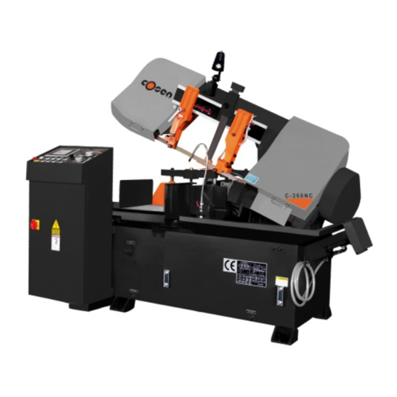
- Page 1 Pag.1 & P NSTRUCTION ARTS ANUAL Edition A INSTRUCTION & PARTS MANUAL Band Saw Machine type C-260 NC EAR OF PRODUCTION 2001 ERIAL NUMBER 21117...
- Page 2 CE declaration which follows the European Directive 89/392 requirements. DoAll is sure to assure with this machine the state of the art solutions for the opera- tor safety, and to be part of the general improvement of labour conditions.
- Page 3 Pag.3 Instruction & Parts Manual Edition A We declare that the product “Band saw machine type C-260 NC”: Serial number 21117 Year of production 2001 referred to in this declaration is in compliance with : • CEI EN 60204-1 • UNI EN 292/1 •...
- Page 4 Pag.4 Instruction & Parts Manual Edition A INDEX General information 1. General information. 2. Machine identification data. 3. How to use this instruction manual. 4. Manufacturer liability limits. 5. Type of use allowed. 6. Technical description. 7. Machine protections. 8. How to move the machine. 9.
- Page 5 Pag.5 Instruction & Parts Manual Edition A GENERAL INFORMATION This machine has been designed and built adopting the state of the art technologies, and with respect of the European Laws for machine tools. Notwithstanding what above, it is implicit that working underestimating or forgetting the dangers related to this kind of ma- chine can generate, the operator could cause serious injuries to him/herself.
-
Page 6: Goal Of This Manual
Pag.6 Instruction & Parts Manual Edition A 1. GENERAL INFORMATION 1.1. G OAL OF THIS MANUAL This manual wants to explain instructions about how to operate safely, using texts, drawings, pictures and diagrams used by themselves or combined to instruct the operator to use the machine. 1.2. -
Page 7: Machine Identification Data
24Vdc Dangerous area Area around the machine (1.5meters) Working place Machine control panel Type of tool Band saw blade Machine Description Band saw machine, type C-260 NC Total amperage 19.5 Maximum power Approximate weight 2.000 TAB 2.2 Technical Characteristics Description... -
Page 8: Main Costructive Characteristics
Pag.8 Instruction & Parts Manual Edition A 2.1 M AIN COSTRUCTIVE CHARACTERISTICS The machine uses : ☺ NC controller with operator display and 28 customizable function keys integrated. ☺ Multi language diagnostic with info messages. ☺ Material libraries. ☺ Band speed readout integrated. ☺... -
Page 9: Strength Of This Manual
ISES Vises are hydraulic. The jaws are tempered. TAB 2.3 Cutting tolerances Machine Description C-260 NC ±0,15 mm / 500 mm On the length On the perpendicularity ±0,2 mm /100 mm 3. HOW TO USE THE INSTRUCTION MANUAL 3.1. W HO SHOULD READ THE INSTRUCTION MANUAL TAB 3.1 Who should read the manual... -
Page 10: Liability Limits
Pag.10 Instruction & Parts Manual Edition A The manufacturer does not have to update this manual if improvements are adopted on newer machines of the same kind of the one this manual make reference to. This manual will be updated by the manufacturer only if : •... - Page 11 Pag.11 Instruction & Parts Manual Edition A • wrong installation of protective equipment after maintenance or service ; • hydraulic or electrical problems due to the producer of the component and not to the producer of the machine ; • big deficiency in maintenance ; •...
-
Page 12: Type Of Use Allowed
Pag.12 Instruction & Parts Manual Edition A 5. TYPE OF USE ALLOWED 5.1. ADDRESSEE MACHINE This machine was design and built to comply a professional use, meaning that, besides the technical knowledge required, it is necessary to have a specific knowledge to operate the saw to obtain the required goals. 5.2. -
Page 13: Workable Materials
Pag.13 Instruction & Parts Manual Edition A Characteristic Cutting speed cmq/m Material feeding speed Mt./m Cutting bridge falling rate (w/o material) Mt./m ∅ 13 ∅ 260 Bars size Bar weight 1.000 5.5. L IMITS USING THE SAW The machine has two limits of use due to : •... -
Page 14: Command Modes
Pag.14 Instruction & Parts Manual Edition A Only authorized people and maintenance personnel should be allowed to reach the saw work place. The operator must be equipped with personal protection instruments, like gloves and safety glasses. 5.9. C OMMAND MODES STOP EMERGENCY STOP AND OUT OF SERVICE 5.9.1 Command modes... -
Page 15: Technical Description
Pag.15 Instruction & Parts Manual Edition A 6. TECHNICAL DESCRIPTION 6.1. M ACHINE STRUCTURE This saw is manly made by : 1. Base frame 2. Cutting bridge 3. Hydraulic power unit 4. Control Panel 5. Coolant system Pos. Tab 6.1. Base frame 6.1.1. - Page 16 Pag.16 Instruction & Parts Manual Edition A Pos. Tab 6.2 Cutting bridge 6.2.1 Cutting bridge frame 6.2.2 Guiding columns 6.2.3 Columns connection 6.2.4 Lifting cylinder 6.2.5 Blade tension assembly 6.2.6 Blade drive assembly 6.2.7 Band brush assembly 6.2.8 Left and right band guide 6.2.9 Cutting servo-control 6.2.10...
-
Page 17: Hydraulic Power Unit
Pag.17 Instruction & Parts Manual Edition A 6.2.8 Left and right band guides. The band guides have to straighten the blade coming out the wheel, and keep it vertical helping the blade insertion between the inserts. Left guide arm : Moves horizontally on guides machined on the bridge, and it is moved by the movement of the vise. Right guide arm : Fixed on the cutting bridge. - Page 18 Pag.18 Instruction & Parts Manual Edition A 6.4.1 Control console The control console is on the upper part of the control enclosure, and all the push-buttons and switches are integrated in the control unit. There is a 5” monitor, which displays the control commands. 6.4.2 Control enclosure It is made bending metal sheets and it complies the IP55 standards.
-
Page 19: Machine Protections
Pag.19 Instruction & Parts Manual Edition A 7. MACHINE PROTECTIONS This machine is entirely protected where it can be dangerous. Despite of this, there are some parts that cannot be protected, and where the operator must never work. The biggest of these parts is where the blade touches material. There is a sticker close to every part which is not completely safe, to show to the operator that he should be extremely con- scious. -
Page 20: Safety Devices
Pag.20 Instruction & Parts Manual Edition A This machine can be installed by: • the manufacturer; • a manufacturer representative ; • the customer. It is customer duty to get the place ready to install the machine, arranging also the anchor bolts to secure the machine on the ground. - Page 21 Pag.21 Instruction & Parts Manual Edition A 11.1 L IMIT SWITCHES AND SEGNALATION DEVICES 11.1.1. Limit switches On the machine there are the following limit switches ESIGNATION ESCRIPTION Home position Out of stock FC5, FC6 Safety band wheel door interlock switches Head down Hed up Blade broken...
-
Page 22: How To Use The Machine
Pag.22 Instruction & Parts Manual Edition A 12.1. H OW TO USE THE MACHINE 12.1.2 First operations When switching the machine on, the SAW3 automatically switchs on too, and it will ask if setting the zero point of the in- dex. - Page 23 Pag.23 Instruction & Parts Manual Edition A To insert a new cutting lenght To delete all the cutting lenght listed in the program To go to the previous page To go to the next page To save 12.1.3 Modifying an existing program By pressing the PGM soft key, the operator can change program variables set while programming the job.
- Page 24 To close the index vise The C-260 NC does not allow a manual cut to avoid possible injuries to the operator. When it is necessary to make a single cut, position the material manually and clamp it with the index vise, then press simultaneously the “SHIFT” and “I” keys.
-
Page 25: Very Important
The only parameters the operator can reset are the “band life” and the “total number of cuts”. VERY IMPORTANT Never modify the machine parameters without a DoAll technician present. This could cause severe injuries to the operator and machine failure. -
Page 26: How To Dismantle The Machine
Pag.26 Instruction & Parts Manual Edition A No tuning-up is needed, because the machine was tuned-up by the manufacturer. 13 HOW TO DISMANTLE THE MACHINE Only experts can dismantle the machine. -
Page 27: Ordinary Problems
Pag.27 Instruction & Parts Manual Edition A 14. ORDINARY PROBLEMS WARNING It is defined as ordinary service the maintenance due to breaks or wear of parts. Even in these circumstances, only expert op- erators should service the saw. They have to be able to work safely knowing which are the machine dangers, and avoiding unnecessary risks. - Page 28 Pag.28 Instruction & Parts Manual Edition A 14.2.4 Blade tension assembly Blade tension assembly Dwg. 210/16 Pos. Tool Adjust the guide track Spanner Check locknut 03-052 Do not regulate the central screw of the blade tension guide 14.2.5 Band drive assembly Band drive assembly dwg.
-
Page 29: Coolant System
Pag.29 Instruction & Parts Manual Edition A 14.2.10 Rapid approach Check that the rapid approach limit switch is in working properly 14.3 COOLANT SYSTEM Check the reservoir level and, if necessary, add oil type OSO46. 14.4 HYDRAULIC POWER UNIT Keep the pressure to 50 bar. 14.5 ELECTRIC CONTROL PANEL Replace, if necessary, broken components. -
Page 30: Maintenance
Pag.30 Instruction & Parts Manual Edition A 15. MAINTENANCE 15.1 L UBRICATION Reducer A Loading plug AGIP BLASIA 150 Replace oil after first 100 hours B Level Check the level every 2000 hours ESSO SPARTAN EP 150 C Unloading plug Replace every 4000 hours MOBILGEAR 632 BP ENERGOL GR-XP150... -
Page 31: Blade Replacement
Pag.31 Instruction & Parts Manual Edition A 15.2. P ROBLEMS Problems Reasons How to solve the problem Twisted cut Feed rate Reduce the feed rate Blade is not perpendicular Register the blade The blade looses the sharpness Cutting speed Reduce the speed quickly Wrong teeth Use a blade with the right teeth... -
Page 32: Remaining Dangers
Pag.32 Instruction & Parts Manual Edition A 16. REMAINING DANGERS This machine is powered by electrical power. The manufacturer, building the machine, used the state of the art solutions also meeting the regarding regulations to assure maximum safety to the operator. When servicing the machine with power on to check particular electrical components, always respects the basic safety rules. - Page 33 XHIBIT ROOF OF TEST This band saw machine: ERIES ERIAL NUMBER C-260 NC Has been tested in accordance with the following norms: " UNI-EN 292-1 " UNI-EN 292-2 " CEI 60204-1 (CEI 44-5) The test had positive result as per testing sheet #...
- Page 34 Pag.34 & P NSTRUCTION ARTS ANUAL Edition A...
- Page 35 Pag.35 Instruction & Parts Manual Edition A...
- Page 36 Pag.36 Instruction & Parts Manual Edition A...
- Page 37 Pag.37 Instruction & Parts Manual Edition A...
- Page 38 Pag.38 Instruction & Parts Manual Edition A...
- Page 39 Pag.39 Instruction & Parts Manual Edition A...
- Page 40 Pag.40 Instruction & Parts Manual Edition A...
- Page 41 Pag.41 Instruction & Parts Manual Edition A...
- Page 42 Pag.42 Instruction & Parts Manual Edition A...
- Page 43 Pag.43 Instruction & Parts Manual Edition A...
- Page 44 Pag.44 Instruction & Parts Manual Edition A...
- Page 45 Pag.45 Instruction & Parts Manual Edition A...
- Page 46 Pag.46 Instruction & Parts Manual Edition A...
- Page 47 Pag.47 Instruction & Parts Manual Edition A...
- Page 48 Pag.48 Instruction & Parts Manual Edition A...
- Page 49 Pag.49 Instruction & Parts Manual Edition A...
- Page 50 Pag.50 Instruction & Parts Manual Edition A...
- Page 51 Pag.51 Instruction & Parts Manual Edition A...
- Page 52 Pag.52 Instruction & Parts Manual Edition A...
- Page 53 Pag.53 Instruction & Parts Manual Edition A...
Need help?
Do you have a question about the C-260 NC and is the answer not in the manual?
Questions and answers