Sign In
Upload
Download
Table of Contents
Contents
Add to my manuals
Delete from my manuals
Share
URL of this page:
HTML Link:
Bookmark this page
Add
Manual will be automatically added to "My Manuals"
Print this page
×
Bookmark added
×
Added to my manuals
Manuals
Brands
DoAll Manuals
Saw
C-4033NC
Instruction manual
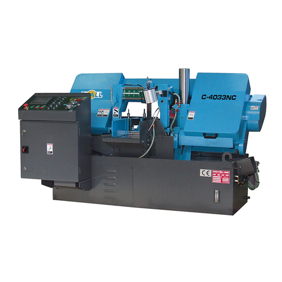
DoAll C-4033NC Instruction Manual
Metal cutting band sawing machine
Hide thumbs
1
2
3
4
Table Of Contents
5
6
7
8
9
10
11
12
13
14
15
16
17
18
19
20
21
22
23
24
25
26
27
28
29
30
31
32
33
34
35
36
37
38
39
40
41
42
43
44
45
page
of
45
Go
/
45
Contents
Table of Contents
Troubleshooting
Bookmarks
Table of Contents
Table of Contents
Safety Rules
Machine Specifications
Machine Dimensions
Installation Dimensions
C-3028NC Dimensions
C-3028NC Boxed Dimensions
C-4033NC Dimensions
C-420NC Dimensions
C-420NC Boxed Dimensions
C-5650NC Dimensions
C-560NC Dimensions
C-6260NC Dimensions
Machine Features
Installations
Locations
OSHA Notice
Unpacking
Lifting
Cleaning
Floor Installation
Electrical Installation
Preparation for Use
Operation
Selecting Band Speed and Cutting Rate
Control Console
Operator Workstation
Setup for Creating Jobs
Machine Preparation
Band Speed Range
Left Saw Guide Arm Adjustment
Feed Force Adjustment
Feed Rate
Head Elevation and Sensing Arm
Minimum Bar End
Vertical Guide Rollers
Hydraulic System
Coolant System
Chip Removal
Nesting Fixture
Typical Operating Procedures
Lubrication
Lubrication Chart
Lubrication Diagrams
Maintenance
Replacing Saw Guide and Backup Inserts
Band/Brush Drive Belt Replacement
Hydraulic System
Coolant System
Band Drive Gear Box
Machine Cleaning
Machine Alignment
Band Brush
Band Tension Measurement
Wear Plate Replacement
Band Wheels
Cleaning Chip Conveyor
Trouble Shooting
Trouble Shooting
Advertisement
Quick Links
1
Selecting Band Speed and Cutting Rate
2
Control Console
3
Trouble Shooting
4
Trouble Shooting
Download this manual
Utility Line
Models:
C-3028NC/BOXED
C-4033NC
C-420NC/BOXED
C-5650NC
C-560NC
C-6260NC
Metal Cutting
Band Sawing Machine
May 2018
Table of
Contents
Previous
Page
Next
Page
1
2
3
4
5
Advertisement
Table of Contents
Troubleshooting
TROUBLE SHOOTING
43
TROUBLE SHOOTING
45
Need help?
Do you have a question about the C-4033NC and is the answer not in the manual?
Ask a question
Questions and answers
Related Manuals for DoAll C-4033NC
Saw DOALL C-820 M Instruction & Parts Manual
(39 pages)
Saw doall c-530 nc Instruction Manual
Band saw machine (72 pages)
Saw DOALL C-530 NC Instruction & Parts Manual
(59 pages)
Saw DoAll C-916S Instruction Manual
Band sawing machine (30 pages)
Saw DoAll C-8056SA Instruction Manual
Metal cutting band sawing machine (26 pages)
Saw DoAll C-530 M Instructions And Parts Manual
Band saw machine type (38 pages)
Saw DoAll C-520NC Instruction Manual
Band saw machine type (34 pages)
Saw DoAll C-4100NC Instruction Manual
Band sawing machine (49 pages)
Saw DoAll C-3028NC Boxed Instruction Manual
Metal cutting band sawing machine (45 pages)
Saw DoAll C-420NC Boxed Instruction Manual
Metal cutting band sawing machine (45 pages)
Saw DoAll C-260 NC Instruction & Parts Manual
Machine (60 pages)
Saw DoAll C-260 NC Instruction & Parts Manual
Band saw machine type (54 pages)
Saw DoAll C-3350NC Instruction Manual
Band sawing machine (40 pages)
Saw DoAll C-7 Instruction Manual
Metalcutting band saw (34 pages)
Saw DoAll C-916 Instruction Manual
Metal cutting band saw (22 pages)
Saw DoAll DS-320SA Instruction Manual
Band saw machines (73 pages)
This manual is also suitable for:
C-3028nc boxed
C-3028nc
C-420nc
C-5650nc
C-560nc
C-6260nc
...
Show all
C-420nc boxed
Table of Contents
Print
Rename the bookmark
Delete bookmark?
Delete from my manuals?
Login
Sign In
OR
Sign in with Facebook
Sign in with Google
Upload manual
Upload from disk
Upload from URL


Need help?
Do you have a question about the C-4033NC and is the answer not in the manual?
Questions and answers