
Related Manuals for DoAll DS-320SA


Summary of Contents for DoAll DS-320SA
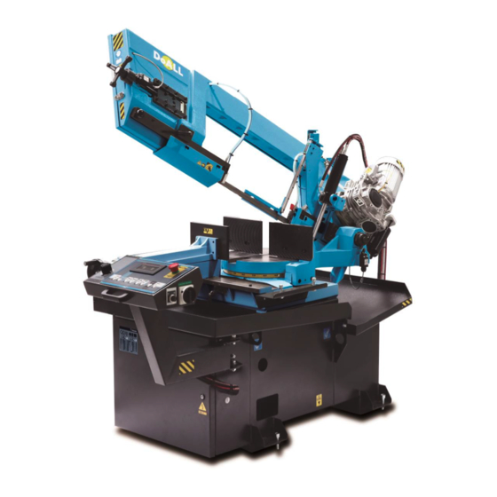
- Page 1 INSTRUCTION MANUAL BAND SAW MACHINES DS-320SA TYPE Version II.generation – version 2 DoALL Sawing Products 800-321-9913 5505 West 123rd Street Minneapolis, MN 55378 www.doallsaws.com...
-
Page 2: Table Of Contents
DS-320SA CONTENT 1. CONTENT ..............................2 2. INTRODUCTION ............................4 2. DESCRIPTION OF THE MACHINE ....................... 4 2.1 OPERATING CYCLE ..........................4 2.2 CONTROL SYSTEM ..........................4 2.3 CONSTRUCTION ............................ 5 2.4 STANDARD EQUIPMENT ........................5 2.5 BASIC EQUIPMENT OF MACHINE ......................5 2.5.1... - Page 3 DS-320SA 9.8.2 ADJUSTMENT OF THE DOWN WORKING POSITION ............38 9.9 VICE ADJUSTMENT - HOW TO CLAMP THE MATERIAL WELL ............39 9.10 GUIDE POSITION ADJUSTMENT ...................... 39 9.11 LUBRICATION OF THE SAW - BAND ....................40 9.12 HOW TO SET THE ADJUSTABLE END STOP ................. 40 9.13 HANDLING THE MATERIAL .......................
-
Page 4: Introduction
DS-320SA 2. INTRODUCTION The Instruction Manual was written to comply with the rules and regulations established by the Federal Trade Commission (FTC) for equipment being sold to customers. The Instruction Manual contains installation, operation and safety instructions. The operator should read the manual and keep it handy for future reference. -
Page 5: Construction
DS-320SA 2.3 CONSTRUCTION The machine is designed in that way, so that it corresponds to extreme exertions in productive conditions. The arm on the machine is designed to make precision cuts. The arm is sloped twenty-five degrees to increase blade life. -
Page 6: Set Of Tools For Common Service
DS-320SA 2.5.1 SET OF TOOLS FOR COMMON SERVICE Item Descritpion Allen wrenches Allen wrench for blade tightenns Wrenchs pic: 2-1 www.doallsaws.com Instruction Manual - 6 -... -
Page 7: Purpose Of The Machine
When ordering maintenance service, always give the name and model of the sawing machine, year of production, serial number, name and code of the spare part. Describe the malfunction as clearly as possible. band saw machine DS-320SA it is a product that answers demands of technical directives. www.doallsaws.com Instruction Manual... -
Page 8: Technical Data
DS-320SA TECHNICAL DATA To achieve the right function of the machine and the safety of the operator following data can not be changed in any case: Protection by cover IP44 performance parameters drive of the blade drive of the hydraulic agregate... -
Page 9: Information On Drive
DS-320SA 3.3 INFORMATION ON DRIVE rated rated rated Turns performance type output voltage current [*min-1] [l/min] Pn [hp] Un [V] In [A] Indukta – 1745 M1 - blade 3SIEK90L4A Varvel: SRT08528G635, i=28 M1 - gearbox 4COA2-14 HP1+S - 0,17 M2 – coolant pump... -
Page 10: Production Label
Specifications contained herein were in effect at the time this manual was approved for printing. The DoALL Company, whose policy is one of continuous improvement, reserves the right, however, to change specifications or design at any time without notice and without incurring obligations. -
Page 11: Main Parts And Functions
DS-320SA MAIN PARTS AND FUNCTIONS 1. Base of machine 2. Wire installation 3. Control panel 4. Hydraulically operating vice for clamping of material. The adjustment is manual with a wheel and trapeze thread. 5. Screw for manually tightening of the band. -
Page 12: Vice
DS-320SA 4.1 VICE 1. Crank for manual operation of the moveable jaw 2. Short step hydraulic cylinder of the vice 3. Locking lever for a quick setting of the jaw, pressed lever control the spring and release the trapese seminut, it is possible to move with the jaw according to your needs 4. -
Page 13: Arm
DS-320SA 4.2 ARM 1. Microswitch of the pulley guard 2. Tensioning pulley 3. Fixed band guide 4. Band cleaning brush 5. Drive pulley 6. Adjustable guide of the saw-band. Washed by coolant. 7. Band tensioning 8. Locking lever of the adjustable guide 9. -
Page 14: Hydraulic Unit
DS-320SA 4.3 HYDRAULIC UNIT pic: 4-4 1. Motor 2. Pressure regulation screw 3. Pressure gage of the main hydraulic circuit 4. Oil plug 5. Reservoir oil 6. Drain plug 7. Hydraulic valve -main vice 8. Hydraulic valve - arm of the machine www.doallsaws.com... -
Page 15: Safety Rules
14. Never clutter the working space with tools or unnecessary objects. 15. After finishing work, the operator turns off the main power switch. 16. When troubleshooting problems with the saw, follow the procedures in the manual or call DoALL (1- 888-362-5572) to schedule an appointment for service. -
Page 16: List Of Possible Dangers When Working With Machine
DS-320SA 34. The machine may only be used for purposes to which it is technically applicable in accordance with the conditions stipulated by the manufacturer and must conform to the safety rules with regard to its design, construction and technical condition. -
Page 17: Electrical Equipment
DS-320SA 5.4 ELECTRICAL EQUIPMENT Work on electrical equipment and can only be performed by licensed contractors with the appropriate electrical qualification. They must be fully acquainted with the equipment. The electrical enclosure on the machine was designed to meet the established electrical requirements, regulations and technical standards for electrical equipment. -
Page 18: Safety Regulations
DS-320SA 5.6 SAFETY REGULATIONS The machine has revolving and moving parts that could hurt you. So it is necessary that there is only one operator who works in the working area of the machine. It is the operator's responsibility to keep others out of the work zone. -
Page 19: Safety Components
DS-320SA 5.6.1 SAFETY COMPONENTS WARNING: The operator is endangered by the rotating or movable parts of the machine. It is prohibited to remove safety covers during machine operation and stop safety, protective and ensuring arrangements ! EMERGENCY STOP button stops all controlling circuits of the machine and band movement. -
Page 20: Description Of Labels
DS-320SA Microswitch of the pulley cover. With the pulley cover closed, the microswitch is closed, and machine operation is enabled. With the pulley cover open, the microswitch is open, and machine operation is disabled. pic: 5-8 Microswitch for band tension. - Page 21 DS-320SA Moving part of the machine - when the machine is working or when manipulating with parts labeled like this, be very careful Adjustment label - MAX- the highest value ( speed, force, pressure) - MIN - the lowest value...
-
Page 22: Instructions For Transport
DS-320SA INSTRUCTIONS FOR TRANSPORT Use a forklift truck (low or high) when moving the machine a short distance. Note: To avoid equipment damage, only use personnel who have a forklift certificate to transport the machine. When moving the machine, insert the forklift forks in places that are marked with a label. -
Page 23: Machine Installation
DS-320SA MACHINE INSTALLATION 8.1 INSPECT MACHINE FOR SHIPPING DAMAGES Inspect the machine for damage. If there is visible damage as a result from transporting the machine to the customer's installation site, notify the carrier and the manufacturer immediately to report the damages. -
Page 24: Achoring Instructions
DS-320SA Attention: Make sure that there is enough space for operators, repair, maintenance and material manipulation space when installing the machine. For additional information, refer to Heading 5.6., Safety Regulations. 8.3.2 ACHORING INSTRUCTIONS: Check the foundation to ensure it meets the requirements outlined in Heading 8.2.1, Foundation Requirements. -
Page 25: Installing The Roller Table
DS-320SA pic: 8-2 8.4 INSTALLING THE ROLLER TABLE It is very important to correctly level the conveyors with the plane of machine (plane defined by tangents of supporting rollers, eventually by plane of the table). The machine won’t be cutting straight, the lifespan of the blade, vices and hydraulic cylinder will be lowered and material handling problems will occur if the conveyors are not leveled properly. -
Page 26: How To Anchor Machine To The Floor
DS-320SA 8.5 HOW TO ANCHOR MACHINE TO THE FLOOR Drilled hole in floor D=0,5in, depth 9in Anchor M12 (1/2”), length 8in If the mechanical anchor cannot be used, then the threaded rod M12 (1/2“) can be used, to depth 9in, drill hole D=0,6in, use chemical glue and fix the threaded rod with the glue. -
Page 27: Description Of Main Panel
DS-320SA DESCRIPTION OF MAIN PANEL pic: 9-1 Item Description MAIN SWITCH of the machine that is possible to lock. It serves also as the emergency stop. In 0 position no electric circuit is under voltage. If you want to switch on the machine, turn to 1. When the operator of the machine is absent, we recommend to lock the machine using the padlock. -
Page 28: Keypad
DS-320SA 9.1 KEYPAD pic: 9-2 Button Description Button Description Start the cutting cycle: push both Arm DOWN START buttons simultaneously movement to cut by set cutting speed. In case of press the button with SHIFT together, The bow is moving by fast speed. -
Page 29: Hmi Panel
DS-320SA 9.2 HMI PANEL The MITSUBISHI HMI panel uses the touchscreen technology. The graphical fields described below are activated by touching the center of the symbol with your finger. WARNING: Touch the screen with your clean bare fingers. Do not wear gloves or use any tool (screwdriver, pencil, toothpick, ...) to operate the touchscreen. -
Page 30: Menu
DS-320SA 9.2.2 MENU Following screen will appear after pressing the MENU button. pic: 9-4 Item. Description User parameters Manual saw control: This screen allows the basic saw motions to be controlled. It can be used, for instance, if the keypad has failed. only for authorized personnel (service technician), access under service password. -
Page 31: 1.Par/ User Parameters
DS-320SA 9.3 /1.PAR/ USER PARAMETERS User (i.e. user-adjustable) parameters pic: 9-6 Name Description / Settings Par. 1: Initial band speed The user can set the band speed for starting the saw up with the ON/OFF button default setting: 40 Par. 2:... - Page 32 DS-320SA pic: 9-8 Name Description/Settings Par. 7: Cutting travel delay Setting of the delay of the arm motion to the cut. The arm waits for the time set and only then starts moving to the cut. Par. 8: User DPP position User setting of the top arm position.
-
Page 33: 2.Man/ Manual Saw Control
DS-320SA 9.4 /2.MAN/ MANUAL SAW CONTROL Manual saw control pic: 9-10 Under user´s password (123456) and it´s used in case of blade changing or error message W003 (bleaking or loosing the blade). Machines with hydraulic blade tightening, which have service mode: It is possible to handle with machine by... -
Page 34: Preparations Before Cutting
Before being shipped to the customer's site, the machine is inspected and tested for proper operation by qualified personnel at DoALL. All screws of the hydraulic system must be well tightened. Use two spanners for tightening the screws, one is for socket, one is for nut. -
Page 35: Initiation Of The Machine Into The Stand-By Mode
DS-320SA 9.6 INITIATION OF THE MACHINE INTO THE STAND-BY MODE pic: 9-2 1. The saw must be connected to the mains. 2. Turn on the main switch to position 1 (pos.5). 3. If the saw was turned off with EMERGENCY STOP button (pos. 4) unlock the EMERGENCY STOP button by turning it to the right. -
Page 36: Angle Setting
DS-320SA 9.7 ANGLE SETTING The machine is designed to make linear cuts (vertical cuts) and miter cuts (angle cuts 45° left and 60° right). General angles are adjusted by the nonius. It is possible to equip the machine by digital indication of the angle for a wish. -
Page 37: Digital Pointer Of The Angle (Accessories)
DS-320SA 9.7.3 DIGITAL POINTER OF THE ANGLE (ACCESSORIES) The angle is indicated by the digital pointer on the panel. pic: 9-11 Item Description Actual turn table position (Not standard equipment). RTO: angle is set as the first, moving with turn table after.(Not standard equipment). -
Page 38: Adjustment Of The Working Position
DS-320SA 9.8 ADJUSTMENT OF THE WORKING POSITION 9.8.1 ADJUSTMENT OF THE UPPER WORKING POSITION The machine is equipped by the automatic end stop of the upper position (DPP). The upper working position is set automatically according to the diameter of the cut material. -
Page 39: Vice Adjustment - How To Clamp The Material Well
DS-320SA 9.9 VICE ADJUSTMENT - HOW TO CLAMP THE MATERIAL WELL pic: 9-8 Put the material into the vice Check the position of the material regarding the blade (for a precise cutting it is necessary to cut the front part of the material –... -
Page 40: Lubrication Of The Saw - Band
The operator can regulate the amount of the emulsion using ball joints on individual supplies. Use only coolants supplied by the DoALL company at the recommended blending ratios. Make sure you attach the milling reservoir, emulsion tank or waste-free lubricating system (applicator) in the proper locations. -
Page 41: Cutting - Semiautomatic Cycle
DS-320SA CUTTING - SEMIAUTOMATIC CYCLE 10.1 BASIC CONDITIONS FOR CUTTING The vice must be well arrested before cutting. The turntable must be well arrested before cutting. WARNING: Before starting the cutting cycle the worker must make one cycle without material to be sure that the machine is well adjusted ! 10.2 HYDRAULIC UNIT –... - Page 42 DS-320SA pic: 10-2 a and after it press pic: 10-3 Using go back. E.G: after breaking a communication with frequency converter an error number and description appears at the top of the screen. pic: 10-4 At resolving the system error, it is necessary to restart the frequency converter. Click the error description line.
- Page 43 DS-320SA pic: 10-6 Press to restart the converter. If the system error is cleared, the display stops blinking in red. The machine returns to normal operation. Return using www.doallsaws.com Instruction Manual - 43 -...
-
Page 44: Rules For Optimal Cut
DS-320SA 10.5 15 RULES FOR OPTIMAL CUT 1. Chose the type of machine and accessories ( the way of cutting must be evident and all designs and the quality of material must be clear) 2. the quality of the blade M42, M51 is directly proportional to the hardness of the material to be cut. -
Page 45: Information About The Blade
DS-320SA INFORMATION ABOUT THE BLADE 11.1 TENSIONING OF THE SAW-BAND The band is correctly tensioned when the light on the control panel is active. The band is tensioned by tightening tensioning screw A on the front part of the saw arm. -
Page 46: Band Replacement
DS-320SA 11.2 BAND REPLACEMENT When replacing the saw-band, it is absolutely important to disconnect the machine from the mains socket and turn it on again after the installation of a new band and closing the pulley and band guards. pic: 11-1 1. -
Page 47: Guides Of The Blade
The guides are factory pre-set. If new adjustment is necessary, we recommend ordering maintenance service of the DOALL company. When cutting, try to adjust the front adjustable guide as close to the sawn material as possible. -
Page 48: How To Replace The Cleaning Brush
DS-320SA 11.4 HOW TO REPLACE THE CLEANING BRUSH The right function of the cleaning brush is one of the very important factors to achieve the highest possible blade life. Edges of teeth that aproaches the material must be clean ( without chips). That is why we ask you to check the cleeaning brush and its position to blade teeth. -
Page 49: How To Choose The Right Saw-Blade
There is a connection between the right choice of saw-blade and an ideal output of machine. DoALL company also deals with a production and selling of saw-blades for metals. Warning : In case of wrong choice of teeth shape and size regarding the material to be cut, pulley, bearings, gear box and engine could be overloaded and enormously worn away. -
Page 50: How To Choose The Right Teeth For Cutting
DS-320SA 12.2 HOW TO CHOOSE THE RIGHT TEETH FOR CUTTING The table for choosing saw-blade is attached to the machine. CONSTANT VARIABLE CONSTANT VARIABLE teeth teeth teeth teeth -0,25 -0,8 6/10 -0,6 - 0,6 10/14 0,25-0,4 0,8-1,6 0,6-1,6 0,6 – 1,6... -
Page 51: How To Clamp Material
DS-320SA 12.4 HOW TO CLAMP MATERIAL pic 12-2 Material clamping influences the precision of cut and life cycle of saw-blade. pic 12-3 12.5 SPEED OF ARM MOVEMENT WHEN CUTTING The shape and color of the metal chips removed from the bandsaw helps you with the setting of the right... -
Page 52: Extra Accessories
DS-320SA 12.5.1 EXTRA ACCESSORIES pic: 12-1 CODE OPTION 300-M2V Engine with the gear box- 2 speed 300-F Motor and frequency converter for a fluent change of the circumferential speed of the blade. Measuring end stop which is mounted directly to the machine, length 1m. - Page 53 DS-320SA 300x320 HP Hydraulical upper vice. Hydraulic upper clamping tighten the material in vertical sense by the hydraulic cylinder. 300x320 HP-A Hydraulical upper vice for mounted on the main vice and on the feeding vice. Hydraulic upper clamping tighten the material in vertical sense by the hydraulic cylinder. Set of 2 pcs.
-
Page 54: Mini-Lube
DS-320SA 12.6 MINI-LUBE The mini-lube system lubricates cutting tools in a dissipating manner. Using a spraying process of oil x air achieves a minimum consumption of lubricant while cooling the tool. Use LB 10000 lubrication oil. For correct operation of the mini-lube system, six-bar pressurised air supply is necessary. -
Page 55: Hydraulical Upper Vice
DS-320SA 12.7 HYDRAULICAL UPPER VICE Hydraulic upper vice mounted on the main vice. Hydraulic upper clamping tightens the material in vertical sense by the hydraulic cylinder connected with the cylinder of the main vice. WARNING: upper clamping can be used only when doing vertical cuts, there could be a collision when doing angle cuts. -
Page 56: Controlling Of Upper Thrust
DS-320SA When assembly / dismantle thrust jaw of the upper clamping we recommend to dismantle the whole upper thrust from the vice: open the movable jaw (pos. 6) to maximum and loose screws (pos.1 and 5) , then dismantle upper thrust. -
Page 57: Roller Table
DS-320SA 12.9 ROLLER TABLE To properly connect roller tables to machine DS-320SA is necessary: 1) Before the cutting zone, on input you have to equip machine with LR-RDP. On output you have to use roller table LR-RDZ. To connect directly the table to machine, there is connecting part used – 290 LR-PR –... - Page 58 DS-320SA Connection of the roller table on input (before the cutting zone): pic: 12-4 pic: 12-5 www.doallsaws.com Instruction Manual - 58 -...
- Page 59 DS-320SA Connection of the roller table on output (after the cutting zone): pic: 12-6 pic: 12-7 www.doallsaws.com Instruction Manual - 59 -...
- Page 60 DS-320SA 2) On input is necessary to use roller table LR-RDTP. For output is necessary to use roller table LR-RDTZ. Both those roller tables are being connected directly to machine, no need to use separate connecting parts. pic: 12-8 WARNING: When installing roller tables, it is important to align them correctly with the horizontal level of the saw (i.e.
-
Page 61: Maintenance
Inspect the band for wear; replace the band, if necessary. WEEKLY: If the hydraulic or gear oil does not extrudes, see the regulations for changing the fillings. In other case order DoALL service. To clean and oil all movable parts and leading surfaces. Check the control panel functions. -
Page 62: Lubrication Checking
DS-320SA 13.1 LUBRICATION CHECKING pic: 13-1 position description lubrication Item necessary activities interval (tab. 16-2) dovetail leading for moving of the lubricate surfaces that are in weekly vice contact clean the device weekly Basements of movable jaw of the Apply plastic lubricant... -
Page 63: Recommended Fillings- Intervals For Changing Fillings
Every change of oil must be written down in the Service book by the authorized service of DoALL. In case of missing notice about regular change of oil the warranty will not be considered. Your Service book must be always kept near the machine. -
Page 64: Filling The Tank With Oil
Do not dump the oil on land or dispose of it in waterways. 13.5 FILLING AND CHANGING PUMP COOLANT use only liquids delivered by DoALL – and mix them in recommended proportions. Pay attention to right placement of the tank for chips and liquid tank. ... -
Page 65: Stirring The Coolant
DS-320SA 13.5.1 STIRRING THE COOLANT optimum state : stir the coolant oil permanently and pour it slowly into the lukewarm water when stirring the coolant oil. The mixing will be ideal and you make the right coolant. 13.5.2 PROPORTION OF OIL AND WATER MIXTURE Proportion of oil and water mixture comes from the recommendation of the producer of machines and producer of blades. -
Page 66: Service Instructions
Before you embark on the below-mentioned procedures on your own, you must be sure that you can manage the task. The DoALL company does not vouch for the accuracy of the text or your potential failure. 14.1 ADJUSTMENT OF BAND GUIDES The band guides are factory-adjusted. -
Page 67: Adjustment Of Clearance Between The Saw-Band And Carbide Pads
DS-320SA pic 14-2 14.2 ADJUSTMENT OF CLEARANCE BETWEEN THE SAW-BAND AND CARBIDE PADS ¨ Adjustments of clearance between the belt and the guide plates are made: Loosen the screw A, insert a 0.037in thick plate between the guide plates, and then tighten the screw B. -
Page 68: Adjustment Of The Tensioning Pulley
DS-320SA 14.3 ADJUSTMENT OF THE TENSIONING PULLEY We suggest leaving the adjustment to authorized assistance. Pic: 14-1 The position of the tensioning pulley is pre-set from the factory. The position can be adjusted by means of adjusting screws and nuts. -
Page 69: Adjusting The Hydraulic Pump Pressures
DS-320SA 14.4 ADJUSTING THE HYDRAULIC PUMP PRESSURES: main pressure – preset from the factory, not necessary to change saw-band tensioning pressure – with tensiometer main vice jaw pressure – adjust according to the size and weight of the material; the lower the pressure, the longer the life of mechanical parts of the vice. -
Page 70: Replacing The Coupling Between The Electric Motor And Hydraulic Pump
DS-320SA 14.6 REPLACING THE COUPLING BETWEEN THE ELECTRIC MOTOR AND HYDRAULIC PUMP After replacing (or lubricating) the coupling, make sure to reassemble the parts back into their correct position. There should be a clearance of 0.5 – 1 mm between the heading of the coupling (Pos. 1) and the spacer (Pos. - Page 71 DS-320SA pic: 14-3 www.doallsaws.com Instruction Manual - 71 -...
-
Page 72: How To Solve Problems-Machine
DS-320SA 14.7 HOW TO SOLVE PROBLEMS-MACHINE problem solution blade motor does not work 3,4,5,9 motor of hydraulic circuit does not work 1,2,3,4,5,9,17 el.panel does not shine 6,7,8,9, cooling is insufficient 18,19,20,21,24 cut piece is moving or is deformed 22,23 plug is not in the socket... -
Page 73: Closing
Contact our service department to set up an appointment for service and maintenance on your machine. For Sales, Parts, and Service, call 1-888-362-5572. For a complete machine inspection, schedule a service appointment with a DoALL service technician. For additional information when the customer elects to review the CE Mark Declaration of Conformity for the machine and other certificates, visit the official DoALL website at: www.dosawing.com.
Need help?
Do you have a question about the DS-320SA and is the answer not in the manual?
Questions and answers