Kaba 7104 series Installation Instructions Manual
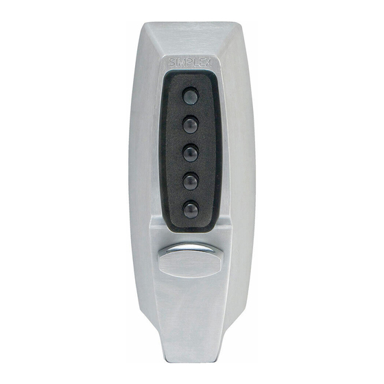
Pushbutton lock
Hide thumbs
Also See for 7104 series:
- Installation instructions manual (16 pages) ,
- Installation instructions manual (40 pages) ,
- Instructions (4 pages)
Table of Contents
Advertisement
Quick Links
Advertisement
Table of Contents

Related Manuals for Kaba 7104 series


Summary of Contents for Kaba 7104 series
- Page 1 English Installation Instructions Pushbutton Lock 7 1 0 4 S E R I E S PK782...
- Page 2 Please keep these instructions. The combination of this lock has been factory preset: 2 and 4 pressed together, then 3. WARNING For your own safety, you must change the combination at the time of installation. PLEASE READ AND FOLLOW ALL DIRECTIONS CAREFULLY Since every installation is unique, carefully check windows, frame, door, etc.
-
Page 3: Table Of Contents
Table of Contents Checklist ......4 Determining the Lock Location ..5 Marking the Door . -
Page 4: Checklist
Checklist Use this checklist to make sure that everything has been included. A - Front Lock B - Adjustable Latch (7104) C - Inside Thumbturn Assembly D - Inside Combination Change Assembly E - Strike Plate Screw Pack: F - 4 thru-bolts (3”) G - 4 combination wood/metal screws 3"... -
Page 5: Determining The Lock Location
Determining the 4" Lock Location Install the lock with the exterior thumbturn at least 7" (18 cm) above your primary lock set so it is comfortable to operate and not in the way when you turn the door knob. 7" (18 cm) *A minimum stile width of 4"... -
Page 6: Drilling Holes In The Door
Drilling Holes in the ⁄ " (19 mm) Hole Door CAUTION: Positioning and drilling must be done straight to ensure troublefree operation of the 7100 Series lockset. Improper drilling may result in excessive force being exerted ⁄ " (6 mm) Holes A on the lock which may result in the 1"... -
Page 7: Making The Latch Face Plate Cutout
Making the Latch Face Plate Cutout This procedure is applicable to wood doors. 1) Insert the latch into the 1" (25 mm) hole until the face plate butts up against the door edge. Draw a line around the face plate, figure 5-1, A. Remove the latch from the door. -
Page 8: Adjusting The Lock
Adjusting the Lock The lock has been pre-assembled to ⁄ accommodate doors up to 2 " (57 mm) ⁄ thick.If your door is 1 " to 2" (35 mm to 51 mm) thick, you must shorten both tailpieces X & Y, figure 7-1. 1) Shorten the combination change tailpiece X according to your door thickness. -
Page 9: Installing The Lock
Installing the Lock ⁄ ⁄ - For 1 " - 1 " (33 - 44mm) thick doors, ⁄ use the 2 " (45mm) thru bolts. ⁄ - For 2"- 2 " (51- 57mm) thick doors, use the 3" (76mm) thru bolts. Mount the lock from the outside of the door. -
Page 10: Checking The Lock's Operation
IMPORTANT: Tailpiece X must be inserted in the horizontal slot in order to change your combination. 5) Make sure that assemblies A and B are correctly centered over the holes, figure 8-4.Tighten the thru-bolts evenly. Uneven tension could cause a malfunction of the lock. - Page 11 7) If the latch does not fully retract, loosen the two thru-bolts of the inside thumbturn assembly. Move the inside thumbturn assembly upward or downward to properly center the inside thumbturn assembly with the tailpiece, (figure 9-2) then tighten the thru-bolts, and repeat Steps 1 to 5. 8) If the latch (figure 9-2) still does not fully retract after repeating Step 7, loosen the two thru-bolts of the inside thumbturn...
-
Page 12: Installing The Strike
Installing the Strike 1) Mark the vertical and horizontal center lines of the strike on the door frame by using the center line of the bolt. Make sure the vertical and horizontal center lines are well aligned with the latch bolt center lines. 2) Where the center lines meet, drill a ⁄... - Page 13 Gently turn to the right (clockwise) ⁄ approximately " (3 mm), figure 11-1. A slight click should be felt. Do not force. IMPORTANT: When removing the screwdriver, the central piece must return to its initial position, if not, set it back to its original position using the screwdriver;...
- Page 14 9) If, without entering the combination, you can retract the latch by turning the outside thumbturn to the right, it means that a step was done out of order and therefore no combination was entered. In this case, you must repeat Steps 1 to 7 but omit Step 2, as the lock does not have a combination.
-
Page 15: Troubleshooting
Buttons of intended combination are not fully depressed when changing combination. This is a lost combination situation. Please call our Technical Service Dept. For further information at (800) 849-TECH. Outside U.S.A. and Canada, please call your KABA ILCO dealer. - Page 16 ONE YEAR WARRANTY This KABA ILCO product is warranted to be free from defects in material and workmanship under normal use and service for a period of one (1) year from date of purchase. However, this warranty does not cover problems arising out of improper installation or use.
Need help?
Do you have a question about the 7104 series and is the answer not in the manual?
Questions and answers