
Subscribe to Our Youtube Channel
Related Manuals for Extraflame COSTANZA IDRO


Summary of Contents for Extraflame COSTANZA IDRO
- Page 1 THERMO PRODUCTS USER MANUAL costanza IDRo MADE ITALY design & production 004277268 - Rev 002...
- Page 2 ENGLISH...
-
Page 3: Table Of Contents
FUMES EXHAUST SYSTEM.............................................11 HydrauLIc SyStEM ...................................... 12 INSTALLATION AND SAFETY DEVICES ......................................12 aNtI-coNdENSatIoN dEVIcE (MaNdatory) ............................13 dEtaILS coStaNZa Idro ..................................... 14 ON/OFF ..................................................14 fEaturES........................................15 cHEckS aNd MEaSurES for coMMISSIoNING ............................15 THE PELLET LOAD MOTOR DOES NOT FUNCTION: ..................................15 bULb THERMOSTATS - REARM ..........................................15... - Page 4 ATTENZIONE TASSATIVO ATENÇÃO - OBrIgATÓrIO PrImA dI mOVImENTArE lA STufA TOglIErE lE mAIO- ANTES dE mOVImENTAr A SAlAmANdrA, rETIrAr AS lIchE INdIcATE PEr EVITArE dANNI. cErâmIcAS INdIcAdAS PArA EVITAr dANOS. PArA O AlINhAmENTO SuPErIOr uSE 4 PArAfuSOS. PEr l’AllINEAmENTO dEl TOP uTIlIZZArE lE 4 VITI. ATTENTION - cOmPulSOrY TÄhElEPANu! BEfOrE mOVINg ThE STOVE, kINdlY TAkE ThE cErA-...
- Page 5 Silicone ENGLISH...
-
Page 6: English
We thank you for having chosen our company; our product is a great heating solution developed from the most advanced technology with top quality machining and modern design, aimed at making you enjoy the fantastic sensation that the heat of a flame gives, in complete safety. Warnings This instructions manual is an integral part of the product: make sure that it always accompanies the appliance, even if transferred to another owner... - Page 7 Š THE GENERATOR MUST NOT BE USED BY PERSONS (INCLUDING CHILDREN) WITH REDUCED PHYSICAL, SENSORY AND MENTAL CAPACITIES OR WHO ARE UNSKILLED PERSONS, UNLESS THEY ARE SUPERVISED AND TRAINED REGARDING USE OF THE APPLIANCE BY A PERSON RESPONSIBLE FOR THEIR SAFETY. Š...
-
Page 8: Routine Maintenance
THAT SWITCH THE GENERATOR OFF. IF THIS OCCURS, CONTACT THE TECHNICAL AFTER-SALES SERVICE AND ALWAYS DISABLE THE SAFETY SYSTEMS. Š IN THE EVENT THE FLUE CATCHES FIRE, USE SUITABLE SYSTEMS FOR SUFFOCATING THE FLAMES OR REQUEST HELP FROM THE FIRE BRIGADE. -
Page 9: Installation
InstallatIOn general The flue gas exhaust and hydraulic connections must be carried out by qualified personnel who must issue installation conformity documentation compliant with national standards. The installer must provide the owner or person acting for him, according to the legislation in force, with the declaration of conformity, supplied with: 1) the use and maintenance manual of the appliance and of the system components (such as for example, the smoke ducts, chimney, etc.);... - Page 10 In the presence of type B gas appliances with intermittent operation not intended for heating, they must have their own aeration and/or ventilation opening. The air inlets must meet the following requirements: Š they must be protected with grids, metal mesh, etc., but without reducing the net useful section; Š...
-
Page 11: Hermetically Sealed Installation
Hermetically sealed installation The generator is a fully sealed product with respect to the environment in which it is installed. This means that it is ideal for passive houses because it does not take air in from within the house. combustion air To ensure the stove remains hermetically sealed, the connection pipe for the combustion air must be directly connected to the exterior, using special pipes and sealed connectors. -
Page 12: Hydraulic System
Standards in force, national, regional and municipal, as well as these instructions. For Italy, installation must be carried out by professionally qualified staff (Ministerial Decree dated 22.01.08 n°37). Extraflame S.p.A. declines all responsibility for damage to objects and/or persons caused by the system. TYPE OF SYSTEM Š... -
Page 13: Anti-Condensation Device (Mandatory)
DISTANCES OF SAFETY DEVICES ACCORDINg TO THE STANDARD The temperature safety sensors must be in place on the machine at a distance no greater than 30 cm from the flow connection. Whenever the generators lack a device, those missing can be installed on the generator flow pipe, within a distance no greater than 1 m from the machine. COMMISSIONINg CHECkS Before connecting the boiler: a) wash all system piping thoroughly in order to remove any residues which might compromise the correct functioning of certain system... -
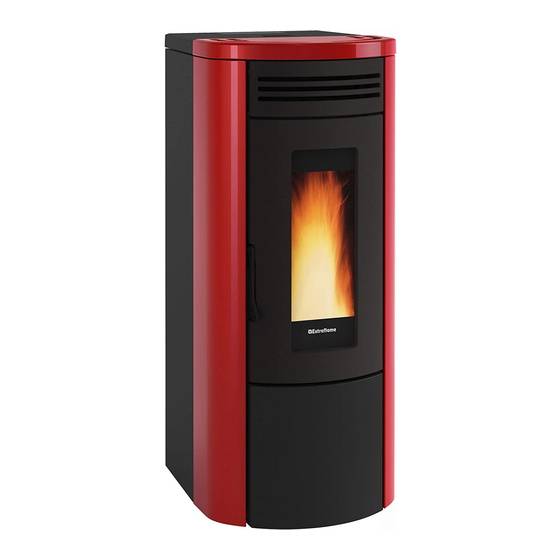
Page 14: Details Costanza Idro
Details COstaNZa iDRO Room air outlet Display Door handle Pellet hopper Access to the ash pressurised closure drawer Room air outlet Combustion air inlet Rearming fumes exhaust On/Off fuse Power supply 230v HyDRauliC iNstallatiON 3 bar safety drain Boiler flow/output... -
Page 15: Features
featuRes Water content of the thermo-product heat exchanger (l) volume of expansion vessel integrated into thermo-product (l) 3 bar safety valve integrated into the thermo-product Minimum and maximum pressure switch integrated into the thermo-product PWM Pump integrated into the thermo-product Pump max. -
Page 16: Stove Positioning
stOve pOsitiONiNg To ensure the stove works correctly, it should always be positioned so that it is perfectly level, using a spirit level. NOte fOR CORReCt OpeRatiON Pellet hopper lid The following indications must be respected for correct pellet stove operation: During stove operation, the pellet hopper lid and the door must always be closed. -
Page 17: Pellets And Feeding
Pellets and feeding Pellets are made by subjecting wood shavings i.e. the rejects of pure wood (without paint) sawmill, carpenter products and products from other activities connected to working and transforming wood, to very high pressures. This type of fuel is fully ecological as no glues are used to hold it together. Indeed, the compactness of the pellets over time is guaranteed by a natural substance found in wood: lignite. -
Page 18: Remote Control
Remote contRol The remote control can be used to adjust the main stove functions. Transmitter Select air mode* Display Lock keyboard On/off stove (hold for 3 seconds) Degrees Celsius / Fahrenheit Set power Press the button once to enable or disable the chrono Set switch-off delay: The button allows to set the switch- off delay. -
Page 19: Remote Control Icons
Remote contRol Icons Air mode selected: * Enable chrono Flashing COMFORT Light on = activated On AUTO Light off = deactivated Indicates the transmission of the radio signal Set switch-off delay * On = during all radio communication Off = radio communication absent Battery low Keys locked Set power level. -
Page 20: Touch Screen Display
TOUCH SCREEN DISPLAY The stove is equipped with a modern touch screen display with WiFi technology that allows for the individual functions of the unit to be adjusted by the user in an easy and intuitive manner. Touch the buttons (icons) on the display to activate the actions. The touch screen display reacts with the touch of you fingers. CAUTION! Š... -
Page 21: Control Board
CONTROL BOARD vieWing oF various TexT messages on/off stove. increase operating power / scroll through the menus. Decrease operating power / scroll through the menus. increase operating thermostat set / scroll through the menus. Decrease operating thermostat set / scroll through the menus. To access the menu / confirm key. -
Page 22: General Menu
gENERAL mENU go back - exit scroll parameters: next (3); previous (2) modify data settings: increase (4); decrease (5) confirm - access menu vENTILATION ENABLINg SPEED EASY SETUP SET THERMOSTAT CHRONO ENABLINg PRg1 PRg2 SETTINgS DATE-TIME PRg3 LANgUAgE PRg4 DISPLAY STAND-BY FIRST LOAD OUTLET AIR... -
Page 23: Commissioning Settings
COmmISSIONINg SETTINgS Once the power cable at the back of the stove has been connected, move the switch, also located on the back, to (I). The switch at the back of the stove powers the stove board. The stove remains off and a first screen appears on the panel reading OFF . mAINS POwER fREqUENCY 50/ 60Hz if the generator is installed in a country with a frequency of 60hz, the display will show "poWer FreQ error". -
Page 24: Operation And Logic
OPERATION AND LOgIC IgNITION once the points listed previously have been checked, press key 1 for three seconds to ignite the stove. 15 minutes are available for the ignition phase. after ignition and having reached the control temperature, the stove interrupts the ignition phase and passes to sTarTing. PREPARATION During the start-up phase, the stove stabilises combustion, increasing it progressively, to then start ventilation and pass on to WorK. -
Page 25: Additional Thermostat
ADDITIONAL THERmOSTAT N.B. : INSTALLATION mUST BE PERfORmED BY AN AUTHORISED TECHNICIAN There is a possibility to control the temperature of a room adjacent to the room where the stove has been placed; simply connect a thermostat following the procedure described in the following section (it is advisable to place the optional mechanical thermostat at a height from the ground equal to 1.50m). -
Page 26: Ventilation
vENTILATION The menu allows you to enable and adjust the speed (-2, -1, 0, +1, +2) of the front fan. enaBLing conTroLs proceDure Š press key 6. Š press 3 until vENTILATION appears and confirm by pressing 6. Š confirm enaBLing by pressing the 6 key. Š... -
Page 27: Chrono
CHRONO This function allows the stove's ignition and switch-off to be automatically programmed. The factory setting for chrono is off. The chrono allows the programming of 4 time slots within a day, which can be used every day of the week. Ignition and switch-off times can be set for each time slot, along with the specific days of application for the programmed time slot, the desired temperature and power setting. - Page 28 EXAMPLE OF CHRONO OvERLAPPINg TIME/SLOTS Time sLoT 02:00 08:00 16:30 23:00 seT poWer 02:00 08:00 16:30 23:00 seT h2o 72° 68° 02:00 08:00 16:30 23:00 start 02:00 Time slot 1 power 3 - seT h2o 72°c stop 23:00 start 08:00 Time slot 2 power 1 - seT h2o 68°c stop 16:30...
-
Page 29: Settings
SETTINgS • DATE-TImE • LANgUAgE See chapter: commiSSioning SettingS. • SET DEgREES DISPLAY This menu allows you to adjust the brightness of the display. The values range from oFF, 1 to 20. if set to oFF, the display backlighting is set to maximum brightness and then, turns off after a 60 second delay. -
Page 30: Wi-Fi
Wi-Fi The display can connect to the internet using Wi-Fi technology. This allows for the stove to be managed and controlled remotely via the special app for smartphones "Totalcontrol 2.0" ( apple store / play store). it is possible to configure the Wi-Fi network directly from the display following this procedure (home network configuration). Wi-Fi enaBLing conTroLs proceDure Š... -
Page 31: Cleaning And Maintenance
TO FIND OUT WHERE YOUR NEAREST SERVICE CENTRE IS, CONTACT YOUR DEALER OR GO TO THE WEBSITE: WWW.LANORDICA-EXTRAFLAME.COM Cleaning and maintenanCe always follow the instruCtions in Complete safety! Š Make sure that the power cord is unplugged because the generator may have been programmed to turn on. - Page 32 burn pot and Combustion Chamber: Š Open the fire door. Š Suck the ash deposited between the partition and the fire door. Š Remove the resistor assembly. Š Remove the burn pot. Š Clean the combustion chamber and the bottom of the burn pot completely, using a suitable vacuum cleaner.
-
Page 33: Routine Maintenance Performed By Qualified Technicians
Qualified person, so as to avoid all risks. TO FIND OUT WHERE YOUR NEAREST SERVICE CENTRE IS, CONTACT YOUR DEALER OR GO TO THE WEBSITE: WWW.LANORDICA-EXTRAFLAME.COM routine maintenanCe performed by Qualified teChniCians routine maintenance must be performed at least once a year. - Page 34 TO FIND OUT WHERE YOUR NEAREST SERVICE CENTRE IS, CONTACT YOUR DEALER OR GO TO THE WEBSITE: WWW.LANORDICA-EXTRAFLAME.COM THE IMAGES ARE FOR ILLUSTRATIVE PURPOSES ONLY. Fumes motor (dismantle and clean the smoke duct and "T"), new seal where required Seals, pallet hopper, inspections, ash drawer and door (replace and apply a new seal where required) Combustion chamber and heat exchanger (full cleaning) including ignition-plug pipe Hopper (complete emptying and cleaning).
- Page 35 TO FIND OUT WHERE YOUR NEAREST SERVICE CENTRE IS, CONTACT YOUR DEALER OR GO TO THE WEBSITE: WWW.LANORDICA-EXTRAFLAME.COM THE IMAGES ARE FOR ILLUSTRATIVE PURPOSES ONLY. Fumes motor (dismantle and clean the smoke duct and "T"), new seal where required Seals, pallet hopper, inspections, ash drawer and door (replace and apply a new seal where required) Combustion chamber and heat exchanger (full cleaning) including ignition-plug pipe Hopper (complete emptying and cleaning).
-
Page 36: Displays
Check pellet feed (see “EASY SETUP”), if the problem cannot be solved, HoT fuMes High fumes temperature contact an authorised technician. TO FIND OUT WHERE YOUR NEAREST SERVICE CENTRE IS, CONTACT YOUR DEALER OR GO TO THE WEBSITE WWW.LANORDICA-EXTRAFLAME.COM ENGLISH... - Page 37 IPWM output interface damaged, in short Contact after-sales centre alaRM circuit or not connected * if there is an additional system data-sheet. TO FIND OUT WHERE YOUR NEAREST SERVICE CENTRE IS, CONTACT YOUR DEALER OR GO TO THE WEBSITE WWW.LANORDICA-EXTRAFLAME.COM ENGLISH...
-
Page 38: Guarantee Terms
Extraflame S.p.A. cannot be held liable for injury or damage which may - either directly or indirectly - be caused to persons, animals and property ensuing from failure to observe all the instructions provided in the relevant instruction manual and the warnings regarding installation, use and maintenance of the product, that can also be downloaded on the website. - Page 39 AddITIONAL wARNINGs Š Only use the fuel recommended by the manufacturer. The product must not be used as an incinerator. Š Do not use the product as a ladder or supporting structure. Š Do not place laundry on the product to dry it. Any clothes-horse or similar objects must be kept at due distance from the product. Danger of fire or damage to the coating.
-
Page 40: Disposal
Disposal InformatIon for management of electrIc and electronIc applIance waste contaInIng batterIes or accumulators This symbol, which is used on the product, batteries, accumulators or on the packaging or documents, means that at the end of its useful life, this product, the batteries and the accumulators included must not be collected, recycled or disposed of together with domestic waste. Improper management of electric or electronic waste or batteries or accumulators can lead to the leakage of hazardous substances contained in the product. - Page 41 ENGLISH...
- Page 42 ENGLISH...
- Page 43 ENGLISH...
- Page 44 The manufacturer reserves the right to vary the characteristics and the data reported in this pamphlet at any moment and without notice, in order to improve its products. This manual, therefore, cannot be regarded as a contract towards other parties. 05/10/2018 004277268-002 – MAN.UT COSTANZA IDRO...
Need help?
Do you have a question about the COSTANZA IDRO and is the answer not in the manual?
Questions and answers