Advertisement
Quick Links
Description and operating instructions
Industrial ETHERNET Rail Switch 2 Family
RS2-TX/TX
i
7
+24V
Fault
+24V*
6
FAULT
P2
P1
Stand by
RM
7
6
5
4
5
4
3
2
2
3
2
1 0
RM
Stand by
1
V.24
Stand by
RS2-TX/TX
RS2-FX/FX ST
i
7
+24V
Fault
+24V*
6
FAULT
P2
P1
Stand by
RM
7
6
5
4
5
4
3
2
1
3
2
1 0
RM
Stand by
1
V.24
Stand by
RS2-FX/FX ST
RS2-FX-SM/FX-LH
i
7 LH
+24V
Fault
+24V*
6 SM
FAULT
P2
P1
Stand by
RM
7
6
5
4
5
4
3
2
2
3
2
1 0
RM
Stand by
1
V.24
Stand by
RS2-FX-SM/FX-LH
Hirschmann. Simply a good Connection.
RS2-FX/FX
i
7
+24V
Fault
+24V*
6
FAULT
P2
P1
Stand by
RM
7
6
5
4
5
4
3
2
2
3
2
1 0
RM
Stand by
1
V.24
Stand by
RS2-FX/FX
RS2-FX-SM/FX-SM
i
7
+24V
Fault
+24V*
6
FAULT
P2
P1
Stand by
RM
7
6
5
4
5
4
3
2
2
3
2
1 0
RM
Stand by
1
V.24
Stand by
RS2-FX-SM/FX-SM
RS2-FX-LH/FX-LH
i
7
+24V
Fault
+24V*
6
FAULT
P2
P1
Stand by
RM
7
6
5
4
5
4
3
2
2
3
2
1 0
RM
Stand by
1
V.24
Stand by
RS2-FX-LH/FX-LH
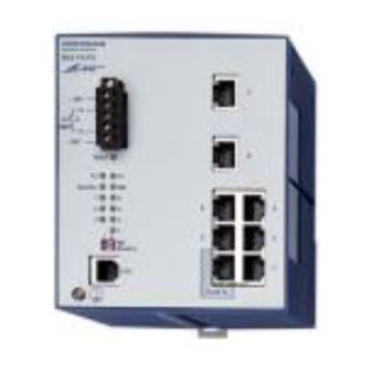
RS2-.../...
Order No.
943 ...-50.
The Rail Switch RS2 has been especially
designed for use in industrial environments.
It supports ETHERNET 10 MBit/s and Fast
ETHERNET 100 MBit/s.
The RS2.../... modules
– RS2-TX/TX
– RS2-FX/FX
– RS2-FX/FX ST
– RS2-FX/FX NAVY
– RS2-FX-SM/FX-SM)
– RS2-FX-SM/FX-LH
– RS2-FX-LH/FX-LH
are manageable. They support SNMP and
Web based management.
The Rail Switch modules support switched
ETHERNET networks in accordance with
IEEE standard 802.3 using copper
technology, and backbones in accordance
with IEEE standard 802.3u using copper
technology or optical waveguide (F/O), in
both line and ring structures. The switch
modules are plugged onto the standard bar.
The RS2.../... modules have five
10/100 Mbit/s twisted pair (TP/TX) ports
(RJ45 connectors) and two backbone ports
(100 Mbit/s Ports). Depending on the model,
the backbone ports to connect further more
RS2-.../... are available with FX or TX inter-
faces (SC or RJ45 connectors).
It is possible to connect data terminal
equipments or other network segments to
the 10/100 Mbit/s ports using twisted pair
cabling TP/TX. The ports support auto
negotiation and autopolarity.
The RS2.../... modules in addition have one
V.24 interface for external management and
one „Stand by" port (RJ45 connector).
The built-in control intelligence supports
redundant links between networks.
In the„RS2-.../... Management Manual –
Industrial ETHERNET Rail Switch 2" you
find a detailled description on the RS2 Rail
Switch.
F, the Hirschmann network manage-
ment system, is the optimum management
solution for this product. Your sales partner
keeps information ready.
Advertisement

Related Manuals for Hirschmann RS2-FX-SM/FX-SM


Summarization of Contents
Safety Instructions
Certified usage
Specifies the approved applications and proper handling of the device.
Safety Guidelines Power Supply
Instructions for safe connection and operation of the power supply.
Safety Guidelines Shielding Ground
Guidance on proper grounding for shielding and preventing short circuits.
Safety Guidelines Housing
Rules for safe operation and installation related to the device housing.
Safety Guidelines Environment
Precautions for operating the device within specified ambient conditions.
Staff qualification requirements
Defines the necessary training and qualifications for personnel.
General Safety Instructions
Notes on CE identification
Information regarding compliance with European directives and certifications.
Based specifications and standards
Lists the technical standards and specifications the device adheres to.
1. Functional description
1.1 FRAME SWITCHING FUNCTIONS
Explains how the device switches and forwards data frames.
1.2 SPECIFIC FUNCTIONS OF THE TP/TX INTERFACE
Details the functions of the Twisted Pair (TP/TX) network ports.
1.3 SPECIFIC FUNCTIONS OF THE F/O INTERFACE
Describes the specific functions of the Fiber Optic (F/O) network ports.
1.4 REDUNDANCY FUNCTIONS
Covers features like HIPER-Ring and redundant coupling for network reliability.
1.5 GMRP
Protocol for distributing multicast information between switches.
1.6 SECURITY
Outlines port security features to prevent unauthorized access.
1.7 FURTHER FUNCTIONS AND FEATURES
Details additional functionalities like diagnosis and reset procedures.
1.8 DISPLAY ELEMENTS
Explains the meaning of various LEDs indicating equipment status.
1.9 CONTROLS
Describes user-operable controls like DIP switches on the device.
1.10 INTERFACES
Details the various physical interfaces available on the device.
2. Configuration
2.1 LINE STRUCTURE
Explains how to build network backbones using line structures.
2.2 REDUNDANT RING STRUCTURE
Describes how to create a redundant ring topology for increased network availability.
2.3 REDUNDANT COUPLING OF NETWORK SEGMENTS
Details how to connect network segments redundantly for fault tolerance.
3. Assembly, startup procedure and dismantling
3.1 UNPACKING, CHECKING
Instructions for checking the package contents and inspecting for damage.
3.2 ASSEMBLY
Guidance on the correct procedure for installing the device.
3.3 STARTUP PROCEDURE
Steps to follow for powering up and initiating the device.
3.4 BASIC SETTINGS
Information on configuring essential parameters like IP addresses.
3.5 DISMANTLING
Procedures for safely removing the device from its installation.
4. Management
4.1 INTODUCTION
Overview of the device's management capabilities and protocols.
4.2 SNMP MANAGEMENT
Details on using SNMP for device configuration and monitoring.
4.3 USER INTERFACE
How to interact with the device using its command-line interface.
4.4 WEB-BASED INTERFACE
Instructions for accessing and using the web interface for management.
4.5 SYSTEM MONITORS
Information on system monitors for software updates and diagnostics.
6. Technical data
Control line (crossover TP cable)
Technical specifications for the control line used in redundant configurations.
Interfaces
Detailed technical specifications for all device interfaces.
Need help?
Do you have a question about the RS2-FX-SM/FX-SM and is the answer not in the manual?
Questions and answers