Table of Contents
Advertisement
INSTALLATION AND
OPERATION MANUAL
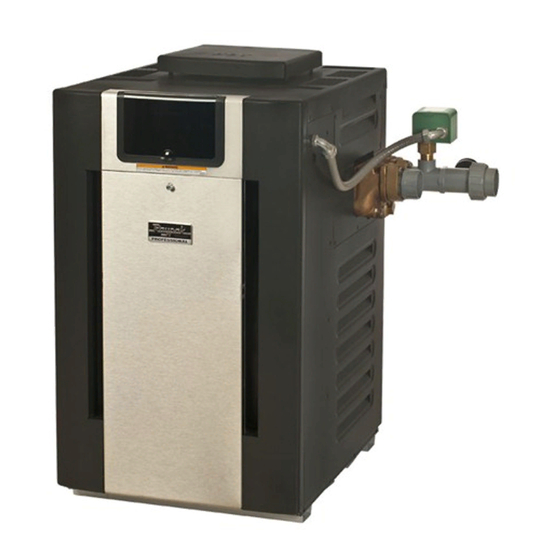
Gas-Fired Pool
and Spa Heater
Atmospheric Models 268 and 408
WARNING: If these instructions are not followed exactly, a fire or explosion may result causing property
A
damage, personal injury or death.
FOR YOUR SAFETY: Do not store or use gasoline or other flammable vapors and liquids or other com-
bustible materials in the vicinity of this or any other appliance. To do so may result in an explosion or
fire.
WHAT TO DO IF YOU SMELL GAS:
• Do not try to light any appliance.
• Do not touch any electrical switch; do not use any phone in your building.
• Immediately call your gas supplier from a neighbor's phone. Follow the gas supplier's instructions.
• If you cannot reach your gas supplier, call the fire department.
Installation and service must be performed by a qualified installer, service agency or the gas supplier.
This manual should be maintained in legible condition and kept adjacent to the heater or in a safe place for future
reference.
Catalog No. 6000.64B
TM
Effective: 07-15-18
Replaces: 11-15-17
P/N 241452 Rev. 3
Advertisement
Table of Contents

Related Manuals for Raypak 408


Summary of Contents for Raypak 408
- Page 1 OPERATION MANUAL Gas-Fired Pool and Spa Heater Atmospheric Models 268 and 408 WARNING: If these instructions are not followed exactly, a fire or explosion may result causing property damage, personal injury or death. FOR YOUR SAFETY: Do not store or use gasoline or other flammable vapors and liquids or other com- bustible materials in the vicinity of this or any other appliance.
- Page 2 Revision 3 reflects the following changes: Manual updated to the new format style. Removed California Proposition 65 warning.
-
Page 3: Table Of Contents
CONTENTS 1. WARNINGS ..............4 5.6. Gas Supply Connections ........16 1.1. Pay Attention to These Terms ......4 5.7. Water Connection Installation ......18 5.8. Unitherm Governor Operation ......18 2. WATER CHEMISTRY ........... 5 5.9. Internal Automatic Bypass Valve ..... 18 2.1. -
Page 4: Warnings
1. WARNINGS 1.1. Pay Attention to These Terms Indicates the presence of immediate hazards which will cause severe personal injury, death or DANGER substantial property damage if ignored. Indicates the presence of hazards or unsafe practices which could cause severe personal injury, WARNING death or substantial property damage if ignored. -
Page 5: Water Chemistry
2. WATER CHEMISTRY • Automatic chemical dosing devices and salt chlorinators are usually more efficient in heated water, unless controlled, they can lead to excessive NOTE: Corrosive water voids all warranties. chlorine level which can damage your heater. Chemical imbalance can cause severe damage to your •... -
Page 6: Operating Instructions
3. OPERATING INSTRUCTIONS 3.3. Visual inspection 3.1. Start-Up Procedures 3.3.1. Atmospheric Heaters Your pool/spa heater has been designed for years of safe With the heater on, remove the door and make a visual and reliable pool/spa water heating. It is available with check of the pilot and burner. - Page 7 CAUTION: Propane gas is heavier than air and will settle on the ground. Since propane can accumulate in confined areas, extra care should be exercised when lighting propane heaters. OPERATING INSTRUCTIONS AND SHUT-OFF PROCEDURES ELECTRONIC IGNITION SYSTEM (AUTOMATICALLY LIGHTED PILOT) *If you cannot reach your gas supplier, call the This appliance is equipped with an ignition fire department.
-
Page 8: Maintenance
(or your gauge is broken). Try to get the pump to run at its Figure 2. Return Header Drain Valve normal flow rate. 5. Check flow switch operation and paddles (“F” paddle on 268 or “A” paddle on 408). -
Page 9: Before Installation
4. BEFORE INSTALLATION Be sure that you receive the number of packages indicated on the Bill of Lading. 4.1. Receiving equipment When ordering parts, you must specify the model and serial numbers of the heater. See below for location of The manufacturer recommends that this manual be serial number. -
Page 10: Clearances
5.2. Clearances Distance Description Location in. (mm) Back 9 (229) 5.2.1. All Heaters Right 9 (229) a. 3-1/2" (89 mm) thick For indoor and outdoors clearances from combustible Left 9 (229) masonry walls without Vent 5 (127) surfaces, see the chart below. ventilated air space Indoor Top 39 (991) -
Page 11: Outdoor Heater Installation
For U.S. installations, the point from where the flue This will enable the heater to be serviced in its installed location, that is, without movement or removal of the heater. products exit the heater must be a minimum of 4' (1.2 m) Clearances less than these (6"... -
Page 12: Combustion And Ventilation Air
5.4. Combustion and Ventilation Air 5.3.3. Outdoor and Indoor Stack The outdoor and indoor stacks are optional equipment 5.4.1. Indoor Units Only and do not come standard with the heater. Refer to installation instructions inside box for instructions on how The heater must have both combustion and ventilation air. - Page 13 FLORIDA AND TEXAS BUILDING CODES WIND SPEED = 150 MPH, 3 SECOND GUST EXPOSURE = C 268/408 ATMOSPHERIC Model 23" (583 mm) 29" (735 mm) 40" (1 m) 28" (709 mm) 2" x 6" x 1/8" Pallet Anchor Bracket (4 Total) (Kit# 011636) 3"...
- Page 14 Prefix “B” is for brass (ASME) headers. Suffix “X” is for cupro-nickel tubing. EXAMPLE: B-R408-EN-X = Brass headers, 408 model size, AFT, natural gas, cupro-nickel. Reduce input 4% for each 1000 ft (305 m) above sea level when installed above 2000 ft (610 m) elevation.
-
Page 15: Vent Piping
6000.57.1. (1.5 m) VENT PIPE DRAFT HOOD Figure 11. Optional Raypak D-2 Power Vent HEATER The unit, when installed as directed, is capable of operating in applications such as through-the-wall venting and reduced horizontal and vertical vent pipe sizes in new Figure 12. -
Page 16: Gas Supply Connections
5.5.1. Appliance Categories 5.6.1. Supply Pressure Heaters are divided into four categories based on the CAUTION: Only sealant tape or a pipe compound rated pressure produced in the exhaust and the likelihood of for use with natural and propane gases is recommended. condensate production in the vent. - Page 17 Gas Pressure Adjustment Figure 18. External Bypass Valve Pressure Drop (Ft of Head) Flow GPM (lpm) 30 (114) Figure 17. Honeywell VR8304 (Heater Models 268 and 408) 40 (151) 50 (189) 5.6.4. Pipe Sizing for Gas Connection 60 (227) 10.5 10.5...
-
Page 18: Water Connection Installation
The heater must be located so that any water leaks will not 5.7. Water Connection Installation damage the structure of adjacent area. High temperature Gather the loose items that were shipped with the heater. 2" plastic pipe (CPVC) may be threaded directly into the header flanges. -
Page 19: External Auxiliary Bypass Valve
5.12. Pressure Relief Valve Installation To conform to local building codes, it may be necessary to install a pressure relief valve. A 3/4" pressure relief valve, having a capacity equal to the BTUH output of the model to be installed, is recommended for this heater. The maximum acceptable pressure relief valve setting is 125 psi. -
Page 20: Electrical Wiring
Plumbing from the heater back to the pool or spa must 6.1. Electrical Power Draw not have any valves or restriction that could prevent flow when the pump is operating. CAUTION: Heater must be electrically grounded and bonded. Bonding lug is provided loose with the heater. CAUTION: An additional source of heated water, e.g. -
Page 21: Transformer Wiring
6.2. Transformer Wiring NOTE: If the transformer’s primary side is wired for 120 VAC and 240 VAC is applied, damage to the transformer and PC board may result. Such damages are not covered 6.2.1. 120 VAC Wiring under manufacturer’s limited warranty. For 120 VAC input power to the unit, connect the black wire to the “L1”... - Page 22 THIS DIAGRAM IS RAYPAK’S RECOMMENDATION AND IS NOT INTENDED TO REPLACE AN ENGINEERED PIPING SYSTEM BY A PROFESSIONAL ENGINEER. Figure 29. Single Pool Heater Installation THIS DIAGRAM IS RAYPAK’S RECOMMENDATION AND IS NOT INTENDED TO REPLACE AN ENGINEERED PIPING SYSTEM BY A PROFESSIONAL ENGINEER.
-
Page 23: Wiring Diagram
7. WIRING DIAGRAM... -
Page 24: Controls
8. CONTROLS 8.2. Control Adjustments The pool heater touchpad, located on the upper front MOUNTED ON RETURN panel of the heater, allows the user to select either POOL HEADER or SPA operation, and to adjust the setpoint temperature. HL2 - HIGH LIMIT MOUNTED ON IN/OUT DRAIN PLUG HEADER... - Page 25 Figure 38. Run Time Indicator Press the DOWN button. The Fault History displays up to ten faults in memory. The order of the faults begins with Figure 34. Alternating Display During Heating “Fault Last,” which is the most recent fault, and proceeds through ten most recent messages in chronological order.
-
Page 26: Status And Diagnostics
Cleared.” Failure to enter the correct PIN will display Set Factory Defaults “Invalid PIN.” Refer to step one above to access the program screen. Set In the event that the user-selected PIN is lost or does not Factory Defaults should appear on the screen. If it does clear the Control Lockout, use the Program Button to Set not, press the MENU/SET button until it appears on the Factory Defaults. - Page 27 The following conditions are displayed in Pool, Spa and 8.4.1. Remote Control Installation and Remote modes. Operation Display Condition CAUTION: Before installing remote controls to the Thermistor temperatures disagree by heaters, read the following: The digital thermostat Sensor Failure more than 2°F (1°C) model is remote-ready in most cases.
-
Page 28: Remote Control Wiring
8.4.3. Activating the Remote NOTE: The remote wires must be connected to the 7-pin connector before the connector is plugged into the board. To activate or deactivate the remote function, follow these steps: 8.5.1. 2-Wire Remote Control (On-Off) 1. Press and hold the UP and DOWN arrow buttons for This application assumes that only one heating function 3 to 5 seconds. - Page 29 On heaters, splice into the red/white wire to connect the time clock. For heaters the fireman’s switch connection is located on the 14-pin header connected to the digital control board. Splice into the red wire jumper tagged “Where necessary add “Fireman’s” switch circuit here” to connect the time clock.
- Page 30 2. Shut off gas upstream of heater. 8.5.5. Flame Roll-Out Safety Switch 3. Remove front door. The heater is equipped with a thermal cutoff device to 4. Disconnect gas line from gas valve. prevent flame roll-out in the event the heat exchanger becomes blocked.
- Page 31 After reaming, mount the wire brush in place of the auger 8.5.11. Pilot Removal And Cleaning and clean out debris remaining in the tubes. Another 1. Disconnect pilot tubing and wires from gas valve. method is to remove the heat exchanger, ream tubes and immerse heat exchanger in non-inhibited de-scale solvent 2.
-
Page 32: Replacement Parts
9. REPLACEMENT PARTS 8.5.17. Unitherm Governor Replacement 1. Shut water, gas and electricity off, close valves and NOTE: To supply you with the correct part, it is important relieve pressure. that you supply the heater model number, serial number and type of gas when applicable. 2. -
Page 33: Troubleshooting
10. TROUBLESHOOTING 10.1. Mechanical IMPORTANT NOTICE: These instructions are intended for the use of qualified personnel who are specifically trained and experienced in the installation of this type of heating equipment and related system components. Installation and service personnel may be required by some states to be licensed. Persons not qualified shall not attempt to install this equipment nor attempt repairs according to these instructions. -
Page 34: Control Logic - Flow Chart
10.2. Control Logic - Flow Chart Power On • Check On/Off switch (under lid on control panel) Is the water • Check for 120/240 volts to the transformer temperature displayed? (time clock, circuit breaker, wire connections) • Check for 24 volts to Circuit Board (P6 connector) “Remote”... -
Page 35: Illustrated Parts List
11. ILLUSTRATED PARTS LIST 15-H 19-H 23-H 13-H 20-H 14-H 10-H 11-H 12-H 20-H 24-H 22-H 21-H 23-H 25-H 22-H 21-H 12-S 18-H 17-H 16-H 18-H 11-S HONEYWELL IID ATMOSPHERIC PILOT 12-M 13-S 11-M 10-S... - Page 36 CALL DESCRIPTION 268A 408A BURNER TRAY Burner Tray w/Burners (sea level)* 013796F 013797F Burner Tray w/o Burners (sea level)* 013798F 013799F Burner Tray w/Gas Valve Nat 013800F 013801F Burner Tray w/Gas Valve Pro 013802F 013803F Burner Spacer/Hold Down Kit 013804F 013805F Burner 301210/18...
- Page 37 CALL DESCRIPTION 268A 408A MISCELLANEOUS COMPONENTS Thermal Fuse 005899F 005899F PRV 125 PSI 011912F 011912F Deliming Kit 052871F 052871F T & P Gauge 014647F 014647F Wire/Harness 013817F 013817F Control Bezel (Includes Switch Decal) 013491F 013491F Switch/Decal-Membrane 013492F 013492F Control Bezel Cover 009487F 009487F Gasket Insulation (Swaybrace &...
- Page 38 NOTES...
- Page 39 NOTES...
- Page 40 Raypak, Inc., 2151 Eastman Avenue, Oxnard, CA 93030 (805) 278-5300 Fax (805) 278-5468 Litho in U.S.A.
Need help?
Do you have a question about the 408 and is the answer not in the manual?
Questions and answers