Table of Contents
Advertisement
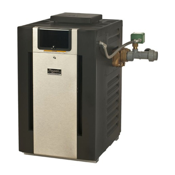
INSTALLATION & OPERATING
Gas-Fired
Pool & Spa
Heater
Atmospheric Models
268 & 408
WARNING: If these instructions are not followed exactly, a fire or explosion may result
causing property damage, personal injury or death.
Do not store or use gasoline or other flammable vapors and liquids in the vicinity of
this or any other appliance.
WHAT TO DO IF YOU SMELL GAS:
• Do not try to light any appliance.
• Do not touch any electrical switch; do not use any phone in your building.
• Immediately call your gas supplier from a neighbor's phone. Follow the gas sup-
plier's instructions.
• If you cannot reach your gas supplier, call the fire department.
Installation and service must be performed by a qualified installer, service agency or
the gas supplier.
This manual should be maintained in legible condition and kept adjacent to the heater or in a safe place for future
reference.
Catalog No. 6000.64
INSTRUCTIONS
TM
Effective: 08-18-11
Replaces: NEW
P/N 241452 Rev. 1
Advertisement
Table of Contents

Related Manuals for Raypak 268


Summary of Contents for Raypak 268
- Page 1 Pool & Spa Heater Atmospheric Models 268 & 408 WARNING: If these instructions are not followed exactly, a fire or explosion may result causing property damage, personal injury or death. Do not store or use gasoline or other flammable vapors and liquids in the vicinity of this or any other appliance.
- Page 2 WATER CHEMISTRY (Corrosive water voids all warranties) For your health and the protection of your pool equipment, it is essential that your water be chemically balanced. The following levels must be used as a guide for bal- anced water. Other Pool & Spa Recommended Level(s) Fiberglass Pools Fiberglass Spas Types...
-
Page 3: Table Of Contents
CONTENTS PART ONE Auxiliary Bypass Valve Adjustment OWNER'S OPERATING INSTRUCTIONS Pressure Relief Valve Installation Plumbing—Water Connections SECTION 1 Electrical Wiring START-UP PROCEDURES Transformer Wiring Before Start-Up Wiring Diagram Operating Instruction & Shut-Off Procedures - SECTION 4 Automatically Lighted Pilots IID SERVICING INSTRUCTIONS After Start-Up General Location of Controls... -
Page 4: Part One
PART ONE OWNER'S OPERATING INSTRUCTIONS FOR YOUR SAFETY - READ BEFORE OPERATING WARNING: IF YOU DO NOT FOLLOW THESE INSTRUCTIONS EXACTLY, A FIRE OR EXPLOSION MAY RESULT, CAUSING PROPERTY DAMAGE, PERSONAL INJURY OR LOSS OF LIFE. SECTION 1 - START-UP PROCEDURES Your pool/spa heater has been designed for years of safe and reliable pool/spa water heating. - Page 5 CAUTION Propane gas is heavier than air and will settle on the ground. Since propane can accumulate in confined areas, extra care should be exercised when lighting propane heaters. OPERATING INSTRUCTIONS AND SHUT-OFF PROCEDURES ELECTRONIC IGNITION SYSTEM (AUTOMATICALLY LIGHTED PILOT) *If you cannot reach your gas supplier, call the This appliance is equipped with an ignition fire department.
-
Page 6: After Start-Up
AFTER START-UP WARNING: Operation of the heater without water circulation will cause rapid and severe damage to Feel the inlet and outlet pipes. Outlet pipe should be the heater, and will void the warranty. only slightly warmer than the inlet. It should not be hot. SECTION 2 - CAUTION WARNING: Should overheating occur or the gas supply fail to shut off, turn off the manual gas control... -
Page 7: Pool & Spa Water Chemistry
5. Check flow switch operation and paddles (“F” pad- tion. dle on 268 or “A” paddle on 408). CAUTION: Soot may be combustible. Wet sooted POOL & SPA WATER CHEMISTRY surfaces completely prior to cleaning. Do not use steel wire brush. -
Page 8: Cold Weather Operation
WINTERIZING THE POOL & SPA HEATER COLD WEATHER OPERATION Heaters installed outdoors in freezing climate areas IMPORTANT FREEZE INFORMATION may be shut down for the winter. Observe the follow- ing procedure for winterizing the heater: MODERATE CLIMATE: Heater operation can contin- ue during short-term cold spells. -
Page 9: Part Two
PART TWO INSTALLATION AND SERVICE INSTRUCTIONS SECTION 1 - RECEIVING EQUIPMENT INSTALLERS - The manufacturer recommends that this manual be reviewed thoroughly before installing the pool/spa heater. If there are any questions that this manual does not answer, please contact the factory or your local representative. -
Page 10: General Specifications
SECTION 2 - GENERAL SPECIFICATIONS These heaters are design-certified and tested under the latest requirements of the ANSI Z21.56 / CSA 4.7 Standard for Gas-Fired Pool Heaters. All heaters can be used either indoor or outdoors. The appropriate top designated for each type of use is required. If necessary, the top can be changed at a later date to change from outdoor to indoor or vice versa. -
Page 11: Clearances
CLEARANCES ALL HEATERS For clearances from combustible surfaces, see the When installed according to the listed minimum clear- chart below. ances from combustible construction, the pool heater can still be serviced without removing permanent CLEARANCE FROM construction around the heater. COMBUSTIBLE CONSTRUCTION However for ease of servicing, we recommend a clear- INDOOR INSTALLATIONS:... - Page 12 Heaters must not be installed under an overhang of less than three 3 ft from the top of the heater. Three sides must be open in the area under the overhang. Roof water drainage must be diverted away from the heaters installed under overhangs with the use of gutters.
-
Page 13: Florida And Texas Building Codes
FLORIDA AND TEXAS BUILDING CODES WIND SPEED = 150 MPH, 3 SECOND GUST EXPOSURE = C 268/408 Atmospheric MODEL # 23” 29” 40” 28” 2” x 6” x 1/8” Pallet Anchor Bracket (4 Total) (Kit# 011636) 3” Min. Conc. Pad by others 1/4”... -
Page 14: Indoor Heater Installation
INDOOR HEATER INSTALLATION The heater is also design-certified for indoor installation when equipped with the approved drafthood. For Canada, indoor installation is restricted to an enclosure that is not occupied and does not directly commu- nicate with an occupied area. Refer to the latest edition of CAN/CSA-B149 for specific requirements. Locate heater as close as is practical to a chimney or gas vent. -
Page 15: Specifications And Dimensions
SPECIFICATIONS AND DIMENSIONS Amp Draw 120 Volt 240 Volt FLUE 10" 6-5/8" 3-3/8" INDOOR DRAFTHOOD 32-11/16" 40" 38" ELECTRICAL STACKLESS CONNECTION OUTDOOR TOP 28-5/8" 13-1/4" CONNECTION 28" Shipping Weights (lbs) Standard ASME BTUH Heater Heater Indoor Heater Input Cabinet Flue Indoor Min. -
Page 16: Combustion And Ventilation Air
CATEGORY III 010745 009833 appliance. Optional Raypak D-2 Power Vent For more information consult the D-2 Power Vent manual, (Catalog No. 6000.57.1). The unit, when installed as directed, is capable of operating in applications such as through-the-wall venting and reduced horizontal and vertical vent pipe sizes in new and current installations. -
Page 17: Gas Supply Connections
The discharge opening must be a minimum of 2 ft ver- GAS SUPPLY CONNECTIONS tically from the roof surface and at least 2 ft higher than any part of the building within 10 ft. Vent stack shall be at least 5 ft in vertical height above the drafthood out- let. -
Page 18: Gas Pressure Regulator
50 125 210 480 445 399.0 95 225 215 480 *A 3/4” gas line can be used for up to 5 ft maximum length from the gas valve in addition to the sediment trap. Honeywell VR8304 (Heater Models 268 and 408) -
Page 19: Flow Rates
HEAT EXCHANGER PRESSURE DROP FLOW RATES MODEL PIPE SIZE MIN. GPM MAX. GPM* PRESSURE DROP (FT OF HEAD) FLOW 1-1/4”–1-1/2” - 2” 1-1/4”–1-1/2” - 2” *When flow rates exceed maximum GPM an external auxil- iary bypass valve is required. See external bypass valve section for details. -
Page 20: Water Connection Installation
The heater must be located so that any water leaks will WATER CONNECTION INSTALLATION not damage the structure of adjacent area. High tem- perature 2" plastic pipe (CPVC) may be threaded Gather the loose items that were shipped with the directly into the header flanges. -
Page 21: Internal Automatic Bypass Valve
INTERNAL AUTOMATIC BYPASS VALVE AUXILIARY BYPASS VALVE ADJUSTMENT In addition to the Unitherm Governor, a built-in auto- To set bypass: With clean filter, adjustment is made by matic bypass valve is provided in the in/out header. feeling the inlet and outlet pipes at the heater. Outlet While the Unitherm Governor responds to the changes pipes should be slightly warmer than inlet and comfort- in water temperature in the heater, the internal bypass... -
Page 22: Plumbing-Water Connections
PLUMBING—WATER CONNECTIONS Single Pool Heater Installation Multiple Pool Heater Installation The heater requires water flow and positive pressure to fire and operate properly. It must therefore be installed downstream of the discharge side of the filter pump. A typical installation is plumbed as follows: 1. -
Page 23: Electrical Wiring
ELECTRICAL WIRING NOTE: If it is necessary to replace any of the original CAUTION: Heater must be electrically grounded and wiring, use 105°C wire or its equivalent, and/or 150°C bonded. Bonding lug is provided loose with the wire or its equivalent, like the original wiring. heater. -
Page 24: Transformer Wiring
TRANSFORMER WIRING 120 VAC WIRING For 120 VAC input power to the unit, connect the black wire to the “L1” or hot leg of the power supply. Connect the white wire to the “Ret” or neutral leg of the power supply. Attach the wire nut to the red wire. There should be no connection to the red wire for 120 VAC operation. -
Page 25: Wiring Diagram
WIRING DIAGRAM... -
Page 26: Servicing Instructions
SECTION 4 - SERVICING INSTRUCTIONS GENERAL LOCATION OF CONTROLS Mounted on Return Header HL2 - High Limit Drain Plug Mounted on In/Out Transformer Header (behind panel) HL1 - High Limit Temp Sensor/Well AFT Thermostat Circuit Board Unitherm Governor Drain Valve Roll-Out Switch Gas Valve Pilot... -
Page 27: Thermostat Operation
THERMOSTAT OPERATION - ADVANCED FLAME TECHNOLOGY (AFT) BOARD Program button LCD Display Temp Buttons Mode Button the pilot flame current using a bar graph and numeri- The pool heater touchpad, located on the upper front cal display. A signal of less than 4 indicates a weak panel of the heater, allows the user to select either flame signal and may require service. - Page 28 Program Button Fahrenheit or Celsius 1) Remove the four screws holding the control cover, Refer to step one above to access the program and swing the panel down so the back side of the screen. Press the Mode button until Fahrenheit or board is visible (see page 26).
-
Page 29: Status And Diagnostics
NOTE: The LCD temperature display may not agree with the temperature reading of your pool or spa ther- mometer. The heater reads the water temperature at the inlet. Due to the circulation characteristics of any pool or spa, the water temperature at the inlet to the heater may differ from that observed at a given location in the pool or spa. -
Page 30: Remote Control Installation And Operation
REMOTE CONTROL INSTALLATION AND OPERATION CAUTION: Before installing remote controls to the heaters, read the following: The digital thermostat model is remote-ready in most cases. The digital liquid crystal display (LCD) shows the actual pool temperature, operating status, and service codes (See examples below). The touch pad on the con- trol panel allows you to select the desired pool or spa temperature. -
Page 31: Remote Control Wiring
REMOTE CONTROL WIRING Important Installation Notes for Remote or External Wiring Configuration • Remote wiring must be run in a separate conduit. • Remote wiring must not be run parallel to high voltage lines. • For runs of under 30 feet, remote wiring should have stranded conductors with a minimum of 22 AWG, 600V, cable twisting 1.5 to 2.5 in. -
Page 32: Time Clock/Fireman's Switch
TIME CLOCK/FIREMAN’S SWITCH FLAME ROLL-OUT SAFETY SWITCH To operate the heater with a time clock, connect the The heater is equipped with a thermal cutoff device to timer to the fireman’s switch connection in the heater’s prevent flame roll-out in the event the heat exchanger wiring. -
Page 33: Pilot Safety
MAIN BURNER AND ORIFICE REMOVAL PILOT SAFETY 1. Remove burner tray. The heater employs a pilot safety which closes the 2. Remove screws and burner hold-down bracket. main gas valve within 8/10ths of a second whenever the pilot flame is interrupted. The pilot flame is auto- NOTE: If the heat exchanger is sooted badly, the matically lit when the device is powered. -
Page 34: Heat Exchanger Removal
Extension Pieces (2) Auger with Carbide Tip Wire Brush HEAT EXCHANGER REMOVAL 1. Remove top and flue collector from cabinet. 1. Shut water, gas and electricity off, close valves 2. Remove "V" baffles from heat exchanger. and relieve pressure, then remove relief valve. 3. -
Page 35: Unitherm Governor (U.g.) Replacement
UNITHERM GOVERNOR (U.G.) REPLACEMENT 1. Shut water, gas and electricity off, close valves and relieve pressure. 2. Drain heat exchanger. 3. Remove retainer plug located next to the outlet pipe connection. 4. Unsnap old U.G. to remove from retainer plug. Snap in new U.G. -
Page 36: Troubleshooting
SECTION 5 - TROUBLESHOOTING MECHANICAL IMPORTANT NOTICE These instructions are intended for the use of qualified personnel who are specifically trained and experienced in the installation of this type of heating equipment and related system components. Installation and service personnel may be required by some states to be licensed. -
Page 37: Control Logic - Flow Chart
CONTROL LOGIC - FLOW CHART Power On • Check On/Off switch (under lid on control panel) Is the water • Check for 120/240 volts to the transformer temperature displayed? (time clock, circuit breaker, wire connections) • Check for 24 volts to Circuit Board (P6 connector) “Remote”... -
Page 38: Replacement Parts
SECTION 6 - REPLACEMENT PARTS NOTE: To supply you with the correct part, it is impor- If determined defective by the Company and within warranty, a like part or equal substitution will be tant that you supply the heater model number, serial returned, freight collect. - Page 40 CALL DESCRIPTION BURNER TRAY Burner Tray w/Burners (sea level)* 013796F 013797F Burner Tray w/o Burners (sea level)* 013798F 013799F Burner Tray w/Gas Valve Nat 013800F 013801F Burner Tray w/Gas Valve Pro 013802F 013803F Burner Spacer/Hold Down Kit 013804F 013805F Burner 301210/18 301210/27 Burner Orifice Nat.
- Page 41 CALL DESCRIPTION MISCELLANEOUS COMPONENTS Thermal Fuse 005899F 005899F PRV 125 PSI 007224F 007224F Deliming Kit 052871F 052871F T & P Gauge 007399F 007399F Wire/Harness 013817F 013817F Control Bezel (Includes Switch Decal) 013491F 013491F Switch/Decal-Membrane 013492F 013492F Control Bezel Cover 009487F 009487F Gasket Insulation (Swaybrace &...
- Page 44 Raypak, Inc., 2151 Eastman Avenue, Oxnard, CA 93030 (805) 278-5300 Fax (805) 278-5468 Litho in U.S.A.
Need help?
Do you have a question about the 268 and is the answer not in the manual?
Questions and answers