Table of Contents

Advertisement

INSTALLATION
AND OPERATION
MANUAL
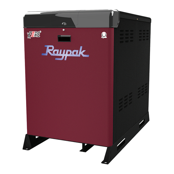
Models 300B - 1000B
Type H and WH
H Only
WARNING: Improper installation, adjustment, alteration, service, or maintenance can cause property
A
damage, personal injury, exposure to hazardous materials*, or loss of life. Review the information in this
manual carefully. *This unit contains materials that have been identified as carcinogenic, or possibly
carcinogenic, to humans.
FOR YOUR SAFETY: Do not store or use gasoline or other flammable vapors and liquids or other
combustible materials in the vicinity of this or any other appliance. To do so may result in an explo-
sion or fire.
WHAT TO DO IF YOU SMELL GAS:
• Do not try to light any appliance.
• Do not touch any electrical switch; do not use any phone in your building.
• Immediately call your gas supplier from a neighbor's phone. Follow the gas supplier's instructions.
• If you cannot reach your gas supplier, call the fire department.
Installation and service must be performed by a qualified installer, service agency or the gas supplier.
This manual should be maintained in legible condition and kept adjacent to the heater or in a safe place for future
reference.
CATALOG NO. 1000.653
Effective: 09-01-19
Replaces: New
P/N 241784

Advertisement

Table of Contents
loading

Summary of Contents for Raypak Xfiire 300B

  • Page 1 INSTALLATION AND OPERATION MANUAL Models 300B - 1000B Type H and WH H Only WARNING: Improper installation, adjustment, alteration, service, or maintenance can cause property damage, personal injury, exposure to hazardous materials*, or loss of life. Review the information in this manual carefully.
  • Page 2 QUICK START GUIDE FOR TYPE H CLEARANCES POWER † Space required: 3 ft. x 7 ft. See page 9. † Supply voltage: See page 23 for input voltage table. † Minimum and service clearances: See page 11 for clearances table. Note that local code prevails. VENTING - CAT IV †...
  • Page 3: Table Of Contents

    CONTENTS 1. WARNINGS ............. 4 Outdoor Installation ..........38 Pay Attention to These Terms ......... 4 Common Venting ..........39 Condensate Treatment ......... 39 2. BEFORE INSTALLATION ........5 5. CONTROLS ............40 Product Receipt ............5 Sequence of Operation ......... 40 Model Identification ..........
  • Page 4: Warnings

    1. WARNINGS Pay Attention to These Terms Indicates the presence of immediate hazards which will cause severe personal injury, death or DANGER substantial property damage if ignored. Indicates the presence of hazards or unsafe practices which could cause severe personal injury, WARNING death or substantial property damage if ignored.
  • Page 5: Before Installation

    All Raypak heaters are National Board registered, and design-certified and tested by the Canadian Standards Thank you for purchasing a Raypak product. We hope you Association (CSA) for the U.S. and Canada. Each will be satisfied with the high quality and durability of our heater is constructed in accordance with Section IV of equipment.
  • Page 6: Component Locations

    Component Locations NOTE: JACKET TOP SLOPES BLOCKED VENT FROM FRONT TO REAR PRESSURE SWITCH FLOW SWITCH FRONT OF HEATER HEAT EXCHANGER DRAIN F10621 HEAT EXCHANGER MODEL 1000B SHOWN. COMPONENT LOCATIONS MAY VARY SLIGHTLY IN SMALLER MODELS. Figure 1. Component Locations – Side View CONTROL DISPLAY ELECTRICAL WATER...
  • Page 7: Water Treatment

    88.0GPM heat exchangers. * When water hardness is higher than 15 GPG, a softener shall be Raypak recommends the using of these corrosion inhibitors used. Water hardness values for calcium carbonate. in preventive and curative treatment for boilers. Table E.
  • Page 8: Installation

    4. INSTALLATION Equipment Base The heater should be mounted on a level, structurally Installation Codes sound surface. Local code may require housekeeping pad. Installations must follow these codes: The heater is approved for installation on a combustible surface but must NEVER be installed on carpeting. Gas- •...
  • Page 9: Clearances

    For ease of servicing, a clearance of at least 30" (762 mm) Clearances in front, at least 24" (610 mm) on the rear. This will allow the heater to be serviced in its installed location without Indoor Installations movement or removal of the heater. Service clearances less than the minimum may require Minimum Clearances from...
  • Page 10 V = VENT X = AIR INLET Figure 10. Minimum Clearances from Vent/Air Inlet Terminations – Indoor and Outdoor Installations U.S. Installations Canadian Installations Clearance above grade, veranda, porch, deck, or 1' (30 cm) 1' (30 cm) balcony 4' (1.2 m) below or to side of Clearance to window or door that may be opened 3' (91 cm) opening...
  • Page 11: Outdoor Installation

    Outdoor Installation NOTE: Vent termination must not terminate under less than 3 ft below eaves, soffits. CAUTION: DO NOT install XFiire heaters outdoors in freezing climates. Combustion and Ventilation Air NOTE: Use of this heater in construction areas where NOTE: Housekeeping pad of adequate height required fine particulate matter, such as concrete or dry-wall dust, for outdoor units to protect heater from standing water.
  • Page 12 NFGC (U.S.) and B149 (Canada), and all local codes. 2. In cold climates, and to mitigate potential freeze- up, Raypak highly recommends the installation of a CAUTION: Combustion air must not be contaminated motorized sealed damper to prevent the circulation...
  • Page 13: Air Supply

    a. Where directly communicating with the outdoors Motorized Combustion Air Dampers D-37 or where communicating to the outdoors through or Louvers vertical ducts, each opening shall have a minimum free area of 1 square inch per 4,000 When motorized dampers or louvers are used for BTUH (550 mm²...
  • Page 14: Water Piping

    Refer to the B149 Installation rated for 160 psi (1100 kPa) operating pressure. However, Code for additional information. Raypak does recommend hydrostatic testing of the piping connections to the heater and the rest of the system prior Water Piping to operation.
  • Page 15: Hydronic Heating

    Feedwater Regulator 5 FT. (1.5 M) MAX. Raypak recommends that a feedwater regulator be in- stalled and set at 12 psi (8.3 kPa) minimum pressure at NOT TO SCALE the highest point of the system. Install a check valve or...
  • Page 16 VERSA IC manual (5000.72). This manual system. Where the system flow may drop below the can be found in the document library at www.raypak.com. connected heater flow a buffer/decoupler may be needed. Failure to design for adequate flow (i.e. bypasses, 3-way control valves, flow-limiting balance devices, buffer tanks, etc.) will result in heater short-cycling and may...
  • Page 17 Mode 1 This mode selection is for hydronic heating systems with single or multiple heaters (maximum 4 heaters) in primary/ secondary piping configuration with or without Outdoor Air Reset (S4). See Figure 16 and Figure 17. The system temperature is controlled by the System Sensor (S3).
  • Page 18 (MASTER) MODBUS VERSA VERSA VERSA VERSA ENABLE 0-10/4-20mA CONNECT SYSTEM PUMP IN PARALLEL FROM EACH CASCADE FOLLOWER OUTPUT FACTORY INSTALLED SENSOR Maximum distance not to exceed 4 pipe diameters or 12" (305 mm) FIELD INSTALLED SENSOR Figure 17. Mode 1 - Recommended Heater Cascade with Primary/Secondary Piping MODBUS VERSA ENABLE...
  • Page 19 Mode 2 This mode selection is for hydronic heating systems with The Heater Pump (P1) is delayed “Off” as user-defined in single or multiple heaters (maximum 4 heaters) in primary/ the Heater menu and the System Pump (P2) is delayed secondary piping configuration with or without Outdoor Air “Off”...
  • Page 20 Mode 3 The Heater/Injection Pump (P1) is delayed “Off” as user- This mode selection is for hydronic heating systems with defined in the Heater menu and the System Pump (P2) is single or multiple heaters (maximum 4 heaters) in primary/ delayed “Off”...
  • Page 21: Gas Supply Connection

    Automatic Chemical Feeders CAUTION: The heater must be disconnected from the gas supply during any pressure testing of the gas All chemicals must be completely diluted into the water supply system at test pressures in excess of 1/2 psi before being circulated through the heater. High chemical (3.45 kPa).
  • Page 22: Electrical Power Connections

    local codes. All primary wiring should be 125% of minimum CAUTION: Support gas supply piping with hangers, rating. not by the heater or its accessories. Make sure the gas If any of the original wire as supplied with the heater must piping is protected from physical damage and freezing, where required.
  • Page 23: Multiple Voltage Configurations

    Multiple Voltage Configurations Making the Electrical Connections The XFiire product supports multiple supply voltages. 1. Verify that circuit breaker is properly sized by referring The following list provides the multiple voltage selection to heater rating plate. A dedicated circuit breaker included in various XFiire product families.
  • Page 24: Field Connected Devices

    Field Connected Devices NOTE: Minimum 18 AWG, 105°C, stranded wire must be used for all low voltage (less than 30 volts) external connections to the heater. Solid conductors should not Field Wiring Connection be used because they can cause excessive tension on contact points.
  • Page 25 Wiring the Optional 0–10 Volt Building Wiring the System Sensor Control Signal NOTE: The System Sensor (S3) is not required for single unit Primary piping configuration. 1. A signal from an energy management system may be connected to the XFiire heater. This signal The System Sensor (S3) is required for all Primary/ should be a 0-10 volt positive DC signal.
  • Page 26 VERSA on the master. For systems requiring more than 4 connected heaters, an external sequencer such as the Raypak Temp-Tracker Mod+ Hybrid can be used. See Figure 29. 2. It is recommended that the shortest length cascade wiring possible be used to reach between the heaters.
  • Page 27: Venting - General

    SYSTEM PUMP 240VAC COIL critical for the safe and efficient operation of the heater. NOTE: Raypak strongly recommends installing the vent system before water piping. This will ensure that the venting system and associated components will fit into Figure 30. XFiire Cascade System Pumps (240VAC the allotted space for proper operation.
  • Page 28 Extractors, Draft Inducers, and Motorized NOTE: additional information appliance categorization, see appropriate ANSI Z21 Standard Combustion Air Dampers and the NFGC (U.S.), or B149 (Canada), or applicable When extractors or inducers are used in the venting provisions of local building codes. system, they must be interlocked with each connected appliance, to ensure proper operation.
  • Page 29 500B 90 Elbow 650B D-15 (6") 6" Z Dens (2ZDP6x), 800B 2ZDTP6 2ZDCPVCG6 (016720) x = 12, 24, 36, 72 in 1000B * Must use Raypak vent terminal specified Table Q. Certified Polypropylene Vent Termination and Adapter - Category IV...
  • Page 30 D-15 (6”) 6" Z Vent (2SVEP0x) 2SVSPRTO6.5 2SVSTTAO6 800B (016720) x = 6.5 in, 1, 1.5, 2, 3, 4 ft 1000B * Must use Raypak vent terminal specified Table R. Certified Stainless Steel Vent Termination and Adapters - Category IV...
  • Page 31: Vent Terminal Location

    2. The vent must not terminate above public walkways Vent Terminal Location due to slip hazard from frozen condensate. NOTE: During winter months check the vent cap and 3. Terminate vent at least 3' (915 mm) above any forced make sure no blockage occurs from build-up of snow air inlet located within 10' (3 m).
  • Page 32: Venting Installation Tips

    Any horizontal sections of a vent must have an upward Venting Installation Tips slope of not less than 1/4" per linear foot from the heater Support piping ( See vent manufacturer's instructions): to the vent terminal. The horizontal portions of the vent shall also be supported for the design and weight of the •...
  • Page 33: Direct Vent-Vertical - Stainless Steel And Polypropylene

    Direct Vent-Vertical - Stainless Steel Termination and Polypropylene The vent terminal must be vertical and must terminate outside the building at least 2' (0.6 m) above the highest Installation point of the roof that is within 8' (2.4 m). The vent cap must have a minimum clearance of 4' (1.2 m) horizontally These installations utilize the heater-mounted blower to from and in no case above or below (unless a 4' [1.2 m]...
  • Page 34: Horizontal Through-The-Wall And Direct Vent - Horizontal - Stainless Steel And Polypropylene

    Horizontal Through-the-Wall and 36" MIN (914 mm) Direct Vent - Horizontal - Stainless Steel and Polypropylene INTAKE D-15 ELBOW The XFiire heaters may be vented horizontally (either using VENT TERMINAL 36" MIN room air for combustion or ducted air for combustion) as (914 mm) shown in the following figures.
  • Page 35: Vertical Venting (Category Iv) - Pvc/Cpvc

    The direct vent cap must be installed at least 1' (305 mm) above ground level and above normal snow levels. The Raypak approved horizontal, stainless steel flue direct vent cap must be used (see Table Q and HEATER UNIT Table R).
  • Page 36: Direct Vent - Vertical - Pvc/Cpvc

    PVC/CPVC Vent Adapter Kits include a 90° SS elbow and a Termination SS to PVC adapter that must be used when installing PVC The vent terminal must be vertical and must terminate or CPVC vent systems. The vent cap is not considered in outside the building at least 2' (0.6 m) above the highest the overall length of the venting system.
  • Page 37: Horizontal Through-The-Wall And Direct Vent - Horizontal - Pvc/Cpvc

    36" MIN (914 mm) 12" MIN CAT IV (305 mm) D-15 VENT TERMINAL VENT TERMINAL INTAKE ELBOW TEST PORT PVC/CPVC 36" MIN VENT PIPE (914 mm) HEATER UNIT INTAKE 12" MIN ELBOW (152 mm) 36" MIN (914 mm) 12" (305 mm) 12"...
  • Page 38: Outdoor Installation

    CONDENSATE PUMP the vent system beyond 36" (914 mm) above the jacket top. Supplemental support is required if the vent extend beyond 36" (914 mm). The Raypak Outdoor Vent Kits contain the following F10573 components: Figure 40. Outdoor Installation •...
  • Page 39: Common Venting

    Raypak does not support common venting under positive- WARNING: Do not install the heater outdoors if pressure conditions. Use an external variable-speed freezing conditions are typical. The condensate will extractor to draw the stack to negative pressure.
  • Page 40: Controls

    Figure 42 is a visual guide only. Follow the manufacturer’s 5. CONTROLS instructions for the installation of the Condensate Treatment Kit and condensate drains. Sequence of Operation 1. Upon initial application of 24VAC power, by toggling the rocker switch to the “IDLE” position the PIM resets with all outputs in the “OFF”...
  • Page 41 10. The PIM initiates a trial for ignition (TFI) counter to 15. If the flow meter detects flow equal to or higher the programmed number of trials for ignition (1 or 3) than the minimum flow requirement, then the unit is and proceeds to Pump Purge mode.
  • Page 42: Versa Integrated Control

    28. On multi-trial-for-ignition models, the control goes through an inter-purge delay before additional ignition attempts are started. If no flame is detected after the FLOW METER final trial-for-ignition, the PIM enters ignition lockout ASSY and the LED on the PIM indicates the fault code for ignition lockout.
  • Page 43 In this scenario, the heater will broadcast an error and alarm. However, it will not stop providing heat. Instead The following fuctions of the VERSA IC are the unit automatically reduces firing rate to minimum firing applicable only if an optional flow meter is rate.
  • Page 44: Glycol % Setting

    • Vent Differential. Subtractive value from max vent Glycol % Setting temperature that defines when the control will take The XFiire product is equipped with algorithms that will action to prevent unit from reaching the max vent ensure optimum operation when using different glycol temperature.
  • Page 45: Control Devices

    Control Devices CAUTION: Failure to set up the Isolation Valve correctly may damage the heater/system pump causing WARNING: Installation, adjustment and service of non-warrantable failures. heater controls, including timing of various operating functions, must be performed by a qualified installer, service agency or the gas supplier.
  • Page 46 Turning off the power to the heater WILL NOT reset the single-try ignition module. TACO VR VIRIDIAN PUMP ETHERNET LED2 LED1 NOTE: Ignition modules are common for all XFiire model sizes. However, model-specific operating parameters are defined by their respective ID cards. 3-Position Rocker Switch RELAY RS485...
  • Page 47 The fixed-setting manual reset high limit is built into the Low Water Cut-Off PIM, and utilizes a dual thermister sensor located on the outlet. The low water cut-off automatically shuts down the burner whenever water level drops below the level of the sensing 200ºF (93ºC) probe.
  • Page 48: User Interface

    Blocked Vent Switch Vent Temp Sensor This heater is equipped with a blocked vent pressure The heater is equipped with a vent temperature sensor. switch to prevent the operation of the heater when too Upon initial installation/comissioning of the heater, the much of the vent is blocked.
  • Page 49 Figure 57. Use Interface Menu - Initial Adjustment To change settings on the touchscreen, press MENU icon, Adjust icon, System settings, System menu to open Adjust Settings menu. The ADJUST menu allows the installer to make adjustments to items shown in Table W. Refer to the VERSA IC Manual (5000.72) for detailed setup instructions.
  • Page 50 This adjustment is for various types and sizes of units as well as various MIX TRIM H MIX -5 to 5 actuator motor speeds and types supplied by Raypak MIX SPEED H MIX SLOW <> MED <> FAST This setting defines speed of response...
  • Page 51 Thermal mass recovery see VERSA IC Manual (5000.72) IDENTITY Identifies the unit as heater, water heater or pool heater IGN TYPE PIM Board type ID CARD Identifies Raypak Identity Card SW ID PIM Software identification number ERROR CODE Current Error Message MIN MOD ADJUST Overrides PIM Low Fire Mod value up to 60% Table X.
  • Page 52 See VERSA IC Manual for details P/N XXXXXX Software number of the Raypak VERSA Resets to factory settings. Press UP and DOWN for 1 second to show CLR and load factory defaults to all DEFAULTS settings. This will also clear all history HISTORY Displayed when an error code is present.
  • Page 53 Outdoor Reset Concept Reset Ratio Settings The Temperature controller can change the System Set The controller uses the four following settings to determine Point based on outdoor temperature (Outdoor Reset). the reset ratio: The temperature controller varies the temperature of the Heater Start (Boil START).
  • Page 54: Wiring Diagram

    6. WIRING DIAGRAM...
  • Page 55: Start-Up

    7. START - UP • Use only your hand to turn the gas control valve handle. Never use tools. If the handle will not turn by hand, do not try to repair it; call a qualified service NOTE: The following steps must be performed by a technician.
  • Page 56: Start-Up

    3. Attach (1) 24" scale manometer to the manifold Start-Up pressure tap located near the shutoff valve downstream of the firing valve (Measure point “C” in NOTE: The values in Table AA and Table AB represent Figure 59). the conditions when the heater is at full firing rate at sea level.
  • Page 57 CO is above 100 ppm in either 1000B -1.0 -1.6 +/-0.2 in.WC case, stop running the unit and contact your Raypak representative. Visit www.raypak.com for contact Table AB. XFiire Manifold Pressure Settings information. CAUTION: Special manifold and air settings may be...
  • Page 58 6. While in operation, check flow switch operation. Number Output Action Field 7. Check the low gas pressure switch (if provided). (For proper adjustment, use the attached manometers, if System Pump relay turns on available, to set pressure. The scales on the switch DHW Pump relay turns on are approximate only.) Low gas pressure switch (if provided) must be set at 3"...
  • Page 59 3. Open test point B and connect a rubber tube to it. 6. Inspect burner to verify flame. Connect the other end of the tube to a manometer 7. Test safety controls: test low water cut-off or and look for a build-up of pressure. Increasing additional safety controls for operation as outlined pressure indicates a leaking gas valve which must by manufacturer.
  • Page 60: Operation

    8. OPERATION Heater Status Light The light operation status of the heater change as follows: Lighting Instructions • White [Solid] - IDLE - Unit is powered on 1. Before operation, make sure you have read all of the • Blue [Pulsing] - PREPURGE/IGNITION - Call for heat safety information in this manual.
  • Page 61: Raymote Troubleshooting

    2. Note the error code, either through the flash code on the PIM and/or from the Toolbox menu on the user interface, and reference the explanation of the fault along with troubleshooting steps in the XFiire fault text section. 3. Investigate and correct the cause of the fault. 4.
  • Page 62: Xfiire Fault Text

    XFiire Fault Text Error Display If there is an active error, then it is displayed in multiple touchscreen views until the error is resolved. For additional error details please refer to the VERSA IC control manual (5000.72). Error Item Description and Troubleshooting OUTLET SEN Check the outlet water sensor and its wiring LIMIT SEN...
  • Page 63 PIM LED Error Code Listing Active errors detected are indicated by LED lights on the PIM. Error Mode LED Flash Code on PIM Recommended Troubleshooting Normal Operation Red LED OFF Red LED Steady ON, Check that the proper ID Card is securely connected. Perform a power and ID Card Fault Green Power LED OFF system reset.
  • Page 64: Maintenance

    10. MAINTENANCE Sensor Resistance Values Suggested Minimum Water Sensor / Outdoor Sensor Maintenance Schedule Water Temperature Resistance (ohms) Regular service by a qualified service agency and 32°F (0°C) 32550 maintenance must be performed to ensure maximum 41°F (5°C) 25340 operating efficiency. 50°F (10°C) 19870 Daily and monthly maintenance as outlined below may be...
  • Page 65: Preventive Maintenance Schedule

    Annually recommended interval is once per year. 1. Test flame failure detection system and pilot NOTE: Use Raypak replacement filters, for models 300B turndown. - 1000B kit number 012553F. 2. Test high limit and operating temperature. See “Post Start-Up Check,” page 59.
  • Page 66: Important Instructions For The Commonwealth Of Massachusetts

    11. IMPORTANT INSTRUCTIONS FOR THE COMMONWEALTH OF MASSACHUSETTS 2. Product Approved side wall horizontally vented gas fueled The Commonwealth of Massachusetts requires compliance with equipment installed in a room or structure separate from regulation 248 CMR 4.00 and 5.00 for installation of through – the dwelling, building or structure used in whole or in part for the –...
  • Page 67 RAYPAK PRODUCTS This start-up checklist is to be completely filled out by the service technician starting up the Raypak boilers or heaters for the first time. All information may be used for warranty purposes and to ensure that the installation is correct. Additionally this form will be used to record all equipment operation functions and required settings.
  • Page 68 Models: 300B-1000B SCOPE Raypak, Inc. (Raypak) warrants to the original owner that all parts of this heater which are actually manufactured by Raypak will be free from defects in materials and workmanship under normal use and service for the specified warranty periods and subject to the conditions set forth in this Limited Warranty.
  • Page 69 REPAIR OR REPLACEMENT At its option, Raypak will repair or replace a defective part(s) in accordance with the terms of this Limited Warranty, if it fails in normal use and service during its specified warranty period. The failed part must first be returned to Raypak if requested, with transportation charges prepaid, and all applicable warranty conditions found satisfied.
  • Page 70 NOTES...
  • Page 71 NOTES...
  • Page 72 ISO 9001 REGISTERED QUALITY MANAGEMENT SYSTEM www.raypak.com Raypak, Inc., 2151 Eastman Avenue, Oxnard, CA 93030 (805) 278-5300 Fax (805) 278-5468 Litho in U.S.A.

Table of Contents