Table of Contents
Advertisement
Quick Links
Advertisement
Table of Contents

Related Manuals for Nibe AG-AC10-65


Summary of Contents for Nibe AG-AC10-65
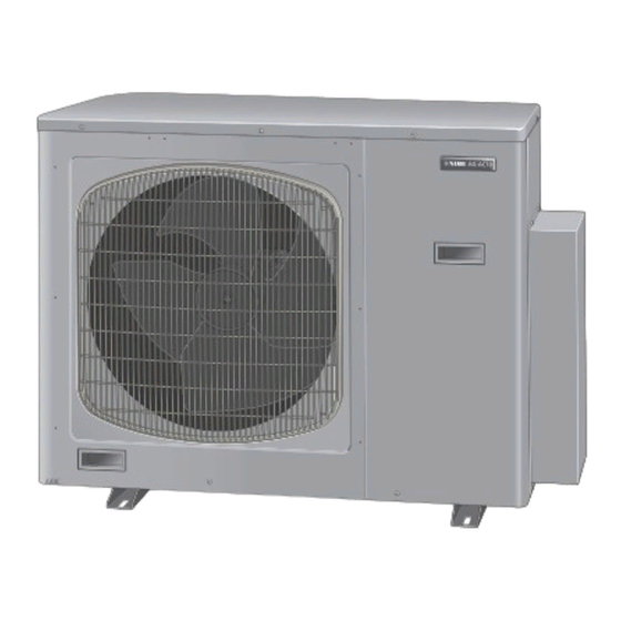
- Page 1 Installer manual AG-AC10 Outdoor unit air/air heat pump IHB GB 1645-1 M12027...
-
Page 3: Table Of Contents
Table of Contents 1 Important information Safety information Read before starting the installation Electrical requirements 2 Delivery and handling Transport Assembly Supplied components 3 Pipe connections General Connecting the cooling circuit Connections 4 Electrical connections General Connections Connecting accessories 5 Installation General Installation instructions Pump down... -
Page 4: Important Information
AG-AC10 is CE marked and meets IPX4. This unit contains a fluorinated greenhouse gas that is The CE marking means that NIBE ensures that the covered by the Kyoto agreement. product meets all regulations that are placed on it based on relevant EU directives. -
Page 5: Read Before Starting The Installation
These instructions are sufficient for installation and maintenance. If assistance is required for a particular problem, contact our dealer for further information. NIBE does not accept any responsibility for damage that occurs in the event of incorrect installation or improper maintenance. -
Page 6: Delivery And Handling
2 Delivery and handling damp areas or easily flooded areas and uneven sur- ■ Transport faces. The outdoor unit should be transported and moved to drill holes in the areas where there are electrical ■ vertically. parts or units. The following is recommended: If possible, select well-ventilated, shaded areas. -
Page 7: Pipe Connections
The pipes must be supplied with at least 8 mm vapour- proof insulation. H1 = Height max 10 m H2 = Height max 5 m Pipe length AG-AC10-65 Number of in- Total length Max. pipe length door per indoor unit... -
Page 8: Connecting The Cooling Circuit
Indoor unit Size A Indoor units with last number -4 Size B Indoor units with last number -7 AG-AC10-65 + one indoor unit Size B AG-DW10 port: for connection refer to the Installer Manual for AG-DW10 Chapter 3 | Pipe connections... - Page 9 AG-AC10-65 + two indoor units Size A Size A AG-DW10 port: for connection refer to the Installer Manual for AG-DW10 Size A Size B AG-DW10 port: for connection refer to the Installer Manual for AG-DW10 Transition nipple 3/8" - 1/2"...
- Page 10 AG-AC10-65 + three indoor units Size A Size A Size B AG-DW10 port: for connection refer to the Installer Manual for AG-DW10 Size A Size A Size A Transition nipple 1/2" - 3/8" AG-DW10 port: for connection refer to the Installer...
-
Page 11: Electrical Connections
4 Electrical connections Connecting to indoor unit General The communication cable must be screened and of the H05VVC4V5-K 2x0.75 type or similar. NOTE The supply cable to the indoor units must be the H07RN- Electrical installation and service must be carried F type. - Page 12 Three indoor units Connection to outdoor unit 3x400V Indoor units Outdoor unit One indoor unit Indoor unit Outdoor unit Two indoor units Indoor units Outdoor unit Chapter 4 | Electrical connections AG-AC10...
-
Page 13: Connecting Accessories
Three indoor units Outdoor unit Indoor units Connecting accessories The outdoor unit is prepared for connection of a condens- ation water pipe (AG-CH10). Caution Also see the Installer Manual for AG-CH10. AG-AC10 Chapter 4 | Electrical connections... -
Page 14: Installation
Indoor unit Indoor unit Outdoor unit units (circuit A) (circuit B) (circuit C) AG-AC10-65 AG-AC10-65 AG-AC10-65 2. Remove the front panel, then connect the supply Installation instructions and communication cables to the outdoor unit and secure them with load relief. - Page 15 3. Use insulated copper cooling pipes. Cut a length of 5. Thread the flange nuts (that were removed from the 30 – 50 cm in addition to the distance between the outdoor unit) on to the pipes and bend up the ends units.
- Page 16 7. Tighten the connections using a wrench and torque wrench according to the tightening torque values in the table. Indoor unit Indoor unit Indoor unit Pipe diameter Tightening torque 6.35 mm (1/4") Approx. 15 – 20 Nm 10. Remove the valve caps from both valves. Now start 9.52 mm (3/8") Approx.
-
Page 17: Pump Down
12. Open the service valves fully (anti-clockwise direc- 2. Start the climate unit in cooling mode. When the tion). Disconnect the vacuum pump. Reinstall the pressure that is read off from the manometer has caps on the valves, tighten to a torque of 20 Nm. dropped to a value less than 0.6 bar (absolute pres- Leak trace caps and connections using a sniffer or sure), the low pressure valve must be closed fully... -
Page 18: Addressing
Addressing Caution The cooling circuit addresses must be set before the system is started. The settings must be made for each of the system's indoor units. See the Installer Manual for the specific indoor unit. Outdoor unit Indoor units Address C Address B Address A Indoor units included in the multisplit system must be... - Page 19 Addressing the indoor unit AG-WL10 Addressing via remote control When addressing using remote control it is possible to connect up to eight indoor units to one outdoor unit. Set the remote control according to the table below, direct it towards the desired indoor unit and keep the buttons "FAN"...
- Page 20 Automatic addressing Function check Caution NOTE Before activating automatic addressing, check It is only necessary to carry out a function check that the indoor unit DIP switch for addressing in systems with several indoor units. is factory set, in "OFF" mode. Run a function check to ensure that the address settings are correct and that the cooling circuits are correctly Activating automatic addressing...
- Page 21 Addressing the indoor unit AG-WT10 Addressing via remote control When addressing using remote control it is possible to connect up to eight indoor units to one outdoor unit. Set the remote control according to the table below, direct it towards the desired indoor unit and keep the buttons "FAN"...
- Page 22 Automatic addressing Function check Caution NOTE Before activating automatic addressing, check It is only necessary to carry out a function check that the indoor unit DIP switch for addressing in systems with several indoor units. is factory set, in "OFF" mode. Run a function check to ensure that the address settings are correct and that the cooling circuits are correctly Activating automatic addressing...
-
Page 23: The Main Functions Of The Valves
6 The main functions of the valves Action 2-way valve (service valve) 3-way valve (service valve) Delivery Valve cap CLOSED O-ring Cone Function and test of OPEN the climate unit Pressure measurement and gas filling OPEN Vacuuming with vacuum pump CLOSED The service valve on the outdoor unit that gives access to the refrigerant system is of the "Schrader"... -
Page 24: Disturbances In Comfort
7 Disturbances in comfort Basic actions Troubleshooting Start by checking the following possible fault sources: NOTE That the climate unit is running or that the supply cable ■ to AG-AC10 is connected. Work behind covers secured by screws may only be carried out by, or under the supervision of, Group and main fuses of the accommodation. -
Page 25: Accessories
8 Accessories Condensation water pipe Route the condensation water pipe to external drain. AG-CH10-10 AG-CH10-30 Length: 1000 mm Length: 3000 mm Part no. 067 466 Part no. 067 467 AG-CH10-60 Length: 6000 mm Part no. 067 468 Hot water module AG-DW10 Hot water module for the multisplit system's outdoor unit AG-AC10. -
Page 26: Technical Data
9 Technical data Dimensions (mm) 1030 Chapter 9 | Technical data AG-AC10... -
Page 27: Technical Specifications
Technical specifications AG-AC10-65 1x230V 3x400V Output data Cooling capacity 35°C / 27°C , min/max 1,570/7,650 Heat capacity 7 °C / 20 °C , min/max 1,820/8,670 Heat capacity -7°C / 20 °C , max 5,920 Heat capacity -22°C / 20 °C... -
Page 28: Electrical Circuit Diagram
Electrical circuit diagram AG-AC10-65 1x230V COMPRESSOR MOTOR MOTOR EXTERNAL INDUCTOR CONTROL BOARD FUSE 1 12,5A EXPANSION VALVE COIL FILTER INDOOR INDOOR INDOOR CONTROL LINE POWER UNIT A UNIT B UNIT C DC 5V SUPPLY INDOOR UNIT A-B-C-DW10 CONNECTION AG-CH10 Chapter 9 |... - Page 29 AG-AC10-65 3x400V COMPRESSOR EXTERNAL MOTOR INDUCTOR MOTOR CONTROL BOARD FUSE 12,5A 12,5A 12,5A EXPANSION VALVE COIL DC BUS 3PH RELAY 3PH RECTIFIER BRIDGE INDOOR INDOOR INDOOR CONTROL LINE POWER SUPPLY UNIT A UNIT B UNIT C DC 5V INDOOR UNIT...
-
Page 30: Item Register
10 Item register Item register Accessories, 25 Addressing, 18 Addressing the indoor unit AG-WL10 Addressing via DIP switches, 19 Addressing via remote control, 19 Addressing the indoor unit AG-WT10 Addressing via DIP switches, 21 Addressing via remote control, 21 Adressering af indendørsenhed AG-WL10 Automatic addressing, 20 Function check, 20 Adressering af indendørsenhed AG-WT10... - Page 32 WS name: -Gemensamt WS version: a294 (working edition) Publish date: 2016-12-08 14:20 37 4255 156 01 NIBE AB Sweden Hannabadsvägen 5 Box 14 SE-285 21 Markaryd info@nibe.se www.nibe.eu M12027...
Need help?
Do you have a question about the AG-AC10-65 and is the answer not in the manual?
Questions and answers