Table of Contents
Advertisement
Advertisement
Table of Contents

Related Manuals for Nibe AG-WL10 series


Summary of Contents for Nibe AG-WL10 series
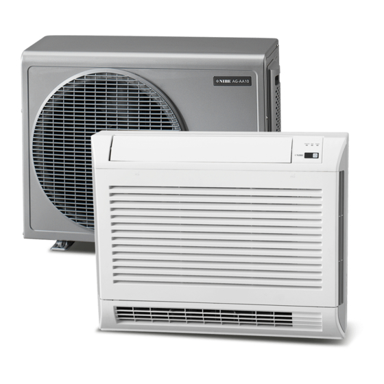
- Page 1 Installer manual AG-WL10 Indoor unit air/air heat pump IHB GB 1637-1 331827...
-
Page 3: Table Of Contents
Table of Contents 1 Important information Safety information Read before starting the installation Electrical requirements 2 Delivery and handling Transport Assembly Supplied components 3 Pipe connections General Connecting the cooling circuit 4 Electrical connection General Connecting indoor and outdoor unit 5 Installation Installation instructions Pump down... -
Page 4: Important Information
Keep hands and clothing away from moving parts. ■ Clean after completing the work, and check that no ■ ©NIBE 2016. metal residue or cable parts have been left inside the unit. Symbols Vent the premises during the installation and the ■... -
Page 5: Read Before Starting The Installation
These instructions are sufficient for installation and maintenance. If assistance is required for a particular problem, contact our dealer for further information. NIBE does not accept any responsibility for damage that occurs in the event of incorrect installation or improper maintenance. -
Page 6: Delivery And Handling
2 Delivery and handling Installation area Transport Minimum working and maintenance range (measured Take care when lifting and moving the indoor unit. in mm): Assembly We recommend that this climate unit be installed by an authorised technician in accordance with the supplied 2000 installation instructions. -
Page 7: Pipe Connections
3 Pipe connections General Only use refrigerant pipes that are seamless, degreased, deoxidized and suitable for a pressure of at least 42 bar. The pipes must be supplied with at least 8 mm vapour- proof insulation. Max 10 m Max 10 m For information about pipe lengths, see the outdoor unit's installer manual. -
Page 8: Electrical Connection
4 Electrical connection General Electrical installation and service must be carried out under the supervision of a qualified electrician. Cut the current with the circuit breaker before carrying out any servicing. Electrical installation and wiring must be carried out in accordance with the stipulations in force. -
Page 9: Installation
5 Installation 4. When installing with bracket, place the bracket on Installation instructions the wall and screw a screw into the centre hole. Align the bracket and mark the holes as illustrated below, 1. AG-WL10 can be connected in six directions: down- two are optional. - Page 10 5. Remove the unit's cover and front. 6. Position the unit where it is to be installed and mark the holes that need to be made for pipe and electric- al connection. Mark any holes to further secure the unit. Chapter 5 | Installation AG-WL10...
- Page 11 7. Drill a hole for the condensation hose and electrical 9. Drill the holes necessary to secure the unit. Check cable at a suitable angle and the correct diameter that the supplied plugs are the correct size and for your unit (see table). Insert and adjust a plastic quantity.
- Page 12 11. When installing on the floor, position the unit in the 13. Remove the cover to access the terminal block as il- desired position and secure the unit with plug and lustrated. screw supplied. 14. Connect the cables to the terminal block. Secure the cable using the cable tie.
-
Page 13: Pump Down
15. Lead out the condensation hose and ensure the Pump down correct fall. Make a water seal if necessary. See the outdoor unit's installation manual for detailed information regarding "Pump down". Pump down means retrieving all refrigerant in the out- door unit without losing the system's filling. -
Page 14: Remote Control
6 Remote control If the unit has received the command, four beeps are Positioning remote control sounded as confirmation. When you have heard the beeps, restart the climate unit to complete the reset. To ensure good unit function, avoid installing the remote control under the following conditions: Coding remote control for Behind a curtain or other covered areas. - Page 15 2. Disconnect the screws and cables as illustrated. 4. Remove the cover from the distribution box to access the DIP switches. 3. Lift out the distribution box containing the circuit board. Remote control Remove the battery cover on the remote control to ac- cess the DIP switches.
- Page 16 Setting DIP switches Set the DIP switches on the indoor unit's circuit board (PCB) and remote control (see table). ■ Insert the batteries into the remote control. ■ Connect power to the indoor unit. ■ The system now restarts with the new settings. ■...
-
Page 17: From Ir To Wire
From IR to wire Wire transfer from the remote control to the indoor unit is appropriate if one wants to posi- tion the remote control in a place where the IR signal between the units cannot reach. To connect the remote control with a cable to the indoor unit, prepare the remote control as follows: Remove the plastic cover from the terminal block. -
Page 18: Addressing The Indoor Unit
7 Addressing the indoor unit Indoor units included in the multisplit system must be configured correctly to be able to communicate with outdoor units over different channels (indoor unitA, in- door unitB, etc.). The address for each indoor unit must correspond to the connection between the indoor unit and outdoor unit's cooling circuit;... -
Page 19: Addressing Via Dip Switches
Addressing via DIP switches When addressing using DIP switches it is possible to connect up to four indoor units to one outdoor unit. See the section "Positioning DIP switches" on the page 14 and set SW2 according to what is indicated in the table. Indoor unit Automatic addressing Hold the ”FAN”... -
Page 20: Function Check
Function check NOTE It is only necessary to carry out a function check in systems with several indoor units. Run a function check to ensure that the address settings are correct and that the cooling circuits are correctly connected. The following steps must be taken with the indoor unit "A". -
Page 21: Disturbances In Comfort
8 Disturbances in comfort In most cases the heat pump detects a malfunction and displays this as an alarm via the indoor unit's LED lamps. Troubleshooting Key to symbols The LED does not come on The LED lights continuously The LED flashes If there is an active error code, the unit fan stops and the air deflector closes. - Page 22 Error LED lamps Possible cause Action code ■ Faulty heat exchanger sensor on the indoor Check that the sensor is connected to the unit. circuit board, according to the electrical wiring diagram. See page 26. ■ Check if the sensor is damaged and replace if necessary.
-
Page 23: Accessories
9 Accessories GSM module AG-BU10 With AG-BU10 you can control the indoor unit via your mobile phone. Part no. 067 449 AG-WL10 Chapter 9 | Accessories... -
Page 24: Technical Data
10 Technical data Dimensions (mm) AG-WL10 Chapter 10 | Technical data AG-WL10... -
Page 25: Technical Specifications
Technical specifications AG-WL10-4 AG-WL10-7 Electrical data Rated voltage 230 V ~ 50 Hz Max. specified power/operating current kW/A 0.012/0.22 0.019/0.35 Pipe connections Pipe connection (liquid) 6.35 (1/4") (inches) Pipe connection (gas) 9.52 (3/8") 12.7 (1/2") (inches) Min. thickness refrigerant pipe Dimensions and weight Weight Width... -
Page 26: Electrical Circuit Diagram
Electrical circuit diagram Chapter 10 | Technical data AG-WL10... -
Page 27: Item Register
11 Item register Item register Accessories, 23 Addressing the indoor unit, 18 Function check, 20 Delivery and handling, 6 Assembly, 6 Transport, 6 Electrical connection, 8 Electrical connection, 8 Function check, 20 Important information, 4 Electrical requirements, 5 Safety information, 4 Serial number, 4 Installation, 9 Installation instructions, 9... - Page 32 WS name: -Gemensamt WS version: a254 WS release date: 2016-09-19 09:29 Publish date: 2016-10-20 12:55 37 4255 164 01 NIBE AB Sweden Hannabadsvägen 5 Box 14 SE-285 21 Markaryd info@nibe.se www.nibe.eu 331827...
Need help?
Do you have a question about the AG-WL10 series and is the answer not in the manual?
Questions and answers