
Subscribe to Our Youtube Channel
Related Manuals for Azbil MagneW Plus+ MGG14C


Summary of Contents for Azbil MagneW Plus+ MGG14C
- Page 1 CM2-MGG31F-2001 MagneW PLUS+ Electromagnetic Flowmeter Fieldbus Transmitter oundation Model MGG14C User’s Manual...
- Page 2 In no event shall Azbil Corporation be liable to anyone for any indirect, special or consequential damages. This information and specifications in this document are subject to change without no- tice.
- Page 3 SAFETY PRECAUTIONS About Icons The safety precautions described in this manual are indicated by various icons. Please be sure you read and understand the icons and their meanings described below before reading the rest of the manual. Safety precautions are intended to ensure the safe and correct use of this product, to prevent injury to the operator and others, and to prevent damage to property.
- Page 4 Safety messages Carefully read this section before installing or operating this device. Cautions for installation WARNING Installation of the device should be done by the expert from the safety perspective. In case of the installation in the hazardous area, follow the regulation/guidance of the explosion-proof.
- Page 5 Turn off the Fieldbus power supply before connecting the Fieldbus cable to the transmit- ter. The transmitter or the Fieldbus power supply can be damaged. This type of damage is not covered by Azbil Corporation’s warranty. Be sure to plug all unused conduit connections with a water tight plug.
-
Page 7: Table Of Contents
Table of Contents 1. Introduction ............1-1 1.1 System configuration . -
Page 9: Introduction
Foundation Fieldbus system. It describes available configurations and provides definitions for all the major parts of the transmitter. MagneW Flowmeter PLUS+ Thank you for purchasing the Azbil Corporation model MGG14C MagneW PLUS+ Flowmeter This system features: • Advanced multi-variable capacity • Digital panel display •... -
Page 10: Foundation Fieldbus
Figure1-2 Remote system 1.2 F Fieldbus oundation The Foundation Fieldbus provides communications and programmability for a single or multiple flowmeter system. Some features of the fieldbus include: • Complies with Foundation Fieldbus H1 (31.25 kbps voltage mode bus) specifications. • Supports the standard Analog Input (AI) function block. •... - Page 11 Figure1-3 System using a F Fieldbus oundation...
-
Page 12: Main Components
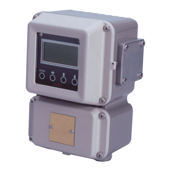
1.3 Main components The transmitter consists of the components shown in the figure below. Figure1-4 Main components (1) Local user interface – Indicates the instantaneous flow rate or the totalized valve. The flowmeter functions can be accessed using the four infrared sensor keys on the panel. (2) Fieldbus interface board –... -
Page 13: Local User Interface
1.4 Local user interface Figure1-5 Local user interface Other than MEASURING Display MEASURING MODE MODE Main display Indicates a value set by PARAM_SELECTION Indicates flow velocity. under the block selected by BLOCK_TAG_SEL. Indicates maximum four values cyclically. Auxiliary display Upper auxiliary display Indicates procedures for the parameter setting or Indicates the information of [Tag, unit, or status]... - Page 14 The following table is a summary of the functions of each of the keys.
- Page 15 How to operate the infrared touch sensor For best results, approach the key from below and completely cover the circle. Then move your finger straight down to its original position. These motions ensure correct operation. Moving sideways across the keys can accidentally activate the wrong control. Figure1-6 Using the touch senser keys...
- Page 16 Local user interface operation The following table describes the functions available in each mode. MEASURING MODE Display Other than MEASURING MODE MEASURING MODE This is the normal operational mode and indicates the measuring status. Each time the MEASURING MODE is selected, data is written into memory.
- Page 17 MEASURING MODE AI – 01 PV Push 3 seconds MODE The screen returns to MEASURING mode in case of no operation for 8 seconds. ENTER BASIC SET Move the cursor under “N” and Move the cursor under “Y” and press key.
- Page 18 BASIC SETUP MODE 2 seconds later MODE ENTER PD TAG 1/2 to Fig1-10 screen ADVANCED YA – RC - 001 PD TAG 2/2 MODE ENTER YA – RC - 001 MAINTENANCE to Fig1-11 screen NODE ADRESS MEMO XXXXXXXX DENSITY 1.0000 DAMPING 003.0 s SVR 10.000 m/s...
- Page 19 & ADVANCED MODE 2 seconds later & COEFFICIENT & MODE RETURN 1.0000 BASIC SETUP & MANUAL ZERO & FLOW SWITCH 2 READY HYSTERISIS & AVARAGING & FLOW SWITCH 2 .00000 & PV SPIKE CUT & FLOW SWITCH 2 MODE LOW &...
- Page 20 > MAINTENANCE MODE > CALIBRATION > SHIPPING INFO > MODE RETURN BASIC SETUP Figure1-10 MAINTENANCE MODE 1-12...
-
Page 21: Overview Of Magnew Plus+ F Oundation Fieldbus
The MagneW Fieldbus communication type employs the specification standardized PLUS+ by the FieldComm Group, and provides interoperability between Azbil devices and those produced by other manufacturers. Fieldbus comes with software consisting of three AI function blocks that enable the flexible implementation of systems. -
Page 22: Function Block Vfd
2200, 2300 For totalization volume * Number of AI becomes three when selecting flow signal analysis function. Flow signal analysis function will be provided as call factory basis. Consult your azbil representative. 2.2.4 Transducer Block Block name... -
Page 23: Vfd/Object Correlation Diagram
2.3 VFD/Object correlation diagram Device Display Senso r Function block VFD FF standard transducer block Resource Display transducer block Basic information control block (FLOW/Positioner/Pressure) Function block Control function Function Function Function VCR control View Trend Alert Object Object Object Link object Communication stack (FMS/FAS/DLL) Physical layer (PHL) -
Page 24: Wiring
, use an M4 screw terminal claw. Some hosts PLUS+ require a connector. Refer to Azbil Corporation when making arrangements to purchase the recommended equipment. Connect the devices as shown in Figure 2-2. Connect the terminators at both ends of the trunk, with a minimum length of the spur laid for connection. -
Page 25: Others
Figure2-2 Cabling 2.5 Others Connect/disconnect the fieldbus devices Before connecting/disconnecting the fieldbus device to the network, make sure this activity does not affect the process. Fieldbus network allows device connection/disconnection to the network while the device circuit is alive. However from the process safety perspective, the device connection/ disconnection to the network after turn off the power is suggested. -
Page 27: Installation
3. Installation Overview This chapter describes the installation and wiring of the device in the following order: - Criteria for selecting the installation environment - Overview of the device installation - Wiring of signal cables WARNING Installation of the device should be done by the expert from the safety perspective. In case of the installation in the hazardous area, follow the regulation/guidance of the explosion-proof. -
Page 28: Before Installing Electromagnetic Flowmeter
3.1 Before installing electromagnetic flowmeter Criteria for selecting the installation environment Getting started Select the optimal location for installing the device according to the following criteria in order to maximize its performance. Note: - Install the device in a location with an ambient temperature of -25 °C to 60 °C (-13 °F to 140 °F) and an ambient humidity of 5 to 100% RH to prevent device malfunction or output errors. -
Page 29: Installation Of Transmitter
3.2 Installation of transmitter Installation of transmitter Basic mounting methods The transmitter can be mounted in three ways—integrated mounting with the flowtube, wall-mounting, and 2B-pipe mounting Mounting plate Terminal box Tag number plate Figure3-1 Wall-mounting of transmitter 2B-pipe mounting 2B-pipe Mounting bracket Material: SPCC (Zinc plating) - Page 30 Turn off the Fieldbus power supply before connecting the Fieldbus cable to the transmit- ter. The transmitter or the Fieldbus power supply can be damaged. This type of damage is not covered by Azbil Corporation’s warranty. Be sure to plug all unused conduit connections with a water tight plug.
- Page 31 - Connection points on the main unit of the electromagnetic flowmeter - Terminal layout - Transmitter terminal table - Cables between flowtube and transmitter - Cable specifications - Connection between flowtube and transmitter - Selection of wiring cable - Installation of wiring cable - Connection to the Fieldbus output Note: - Do not directly connect the AC power supply to the main unit of the electromagnetic...
- Page 32 Terminal layout Figure3-3 Terminal layout of remote transmitter Integral transmitter: Terminal layout Unlike a remote transmitter, an integral transmitter does not use the terminals X, Y, SB, SA, A, B, C, and E. These terminal symbols are thus erased from the layout. DC-24V transmitter: Terminal wiring diagram The power terminal of the DC-24V remote transmitter is indicated as POWER DC 24V.
- Page 33 Please use a special cable (MGA12W) designated for connecting the flowtube and transmitter. Select a signal cable (Azbil’s special cable or a commercially-available shielded cable) depending on the fluid conductance, cable length, and the diameter of the flowtube. Refer to the figure below.
- Page 34 Signal cable (Model: MGA12W) Cable termination on the owtube side Cable termination on the transmitter side Designed for an M4 screw Flowtube Transmitter Designed for an M4 screw side side Designed for an M4 screw Flowtube side (type code A) Flowtube Designed for an M4 screw side...
- Page 35 Excitation cable (Model: MGA12W) Insulator Flowtube Transmitter Designed for an M4 screw side side Designed for an M4 screw Cable termination on the owtube side Designed for an M4 screw Black Flowtube side White (Model code: A) Designed for an M4 screw Black Flowtube side...
- Page 36 Electrical wiring (3) Connection between flowtube and transmitter Dedicated cable model MGA12W Signal cable model MGA12W Signal cable 2-core Converter Single shielded cable Detector Excitation cable model MGA12W Commercially available cable Signal cable 2-core Single shielded cable Converter Detector Excitation cable Figure3-7 Connection between flowtube and transmitter 3-10...
-
Page 37: Startup And Shutoff
4. Startup and Shutoff Overview This chapter describes the procedure for starting up the device and performing zero adjustment. Follow the instructions in this chapter when you start up and operate the device for the first time. Zero adjustment can be made in one of the following ways: Ȳ... -
Page 38: Steps Before Measurement
4.2 Steps before measurement Setting up flowtube data Getting started Select and configure the constant of the flowtube used in combination with the transmitter, flowtube type, and diameter. Default settings The settings of EX 300.0, MGG, and DIA 050.0 are applied when no flowmeter is specified for the combined use with the transmitter. - Page 39 Zero adjustment Getting started Make sure to perform zero adjustment after starting up the device. There are three ways to do so. Ȳ Using the device’s LUI Ȳ Using the parameter list by communicating with the device Ȳ Using the menu by communicating with the device Adjust the measured instantaneous flow rate value to zero when the fluid inside the flowtube is sitting still.
- Page 40 Checking the operation of Fieldbus Check to see if the device operates properly with Fieldbus. Prior to operating Fieldbus, the DD file (device description) and the CF file (capability) of the device need to be copied to the host. Download the DD file and CF file from the official website of the FieldComm Group. Operation of Fieldbus requires the following settings in the host.
-
Page 41: Shutoff
4.3 Shutoff CAUTION · Make sure to switch the controller to manual control mode in order to shut off the device and stop the output to the controller. This safeguards the controller from direct impacts caused by the sus- pended output from the device. ·... -
Page 43: Basic Settings By Fieldbus Communication
5. Basic Settings by Fieldbus Communication Overview This chapter outlines zero adjustment as an operation performed using Fieldbus communication, each Transducer block, as well as basic parameter settings. Some parameters require O/S to be selected for the Block MODE parameter in order to change the settings. -
Page 44: Fieldbus Communication Menu
- Block menu for PCs A compatible host (PC) can display this block menu. A menu prepared for each block displays parameters such as setup and adjustment of the positioner. (Example: Azbil's device management system - InnovativeField Organizer) - Parameter list All parameters are displayed by block. -
Page 45: Zero Adjustment
5.2 Zero adjustment Getting started Once the device has started up, make sure to perform zero adjustment in one of the following three ways. Adjust the measured instantaneous flow rate value to zero when the fluid inside the flowtube is sitting still. Note: - Zero adjustment is extremely important for ensuring accurate measurement of flow rate. -
Page 46: Basic Settings
5.3 Basic settings Flow Transducer Block Overview of function Flow Transducer Block enables calculation of flow velocity, volume flow rate, and mass flow rate based on the sensor outputs of the electromagnetic flowmeter. The calculated volume flow rate and mass flow rate are output to AI Function Block and TOT Function Block. - Page 47 Indicates setting values for the upper and lower range limits, unit, and the position of the decimal point for the volume flow rate. The unit for the flow rate must be identical to the unit assigned for XD_SCALE in AI Block.
- Page 48 Table 5-1. Units that can be set up for volume flow rate Unit of Unit of time volume flow rate /d (1514) /h (1513) /min (1512) /s (1511) /d (1350) /h (1349) /min (1348) /s (1347) L/d (1354) L/h (1353) L/min (1352) L/s (1351) bbl/d (1374)
- Page 49 Display Transducer Block Overview of function Display Transducer Block controls the display of measurement values and alarm indication in the local user interface (LUI). Input and output signal values for function blocks installed in the device can be displayed, such as OUT of AI Block and PRIMARY_VALUE and SECONDARY_VALUE of Flow Transducer Block.
- Page 50 UNIT_SELECTION_n You can select whether the parameter in display setting n will be displayed using the unit associated with it or another desired unit. Select Auto (0) in order to display the parameter with the associated unit as assigned for the displayed value, and select Custom (1) in order to display the parameter with another desired unit.
- Page 51 Several Parameter Display Display Transducer Block can display a maximum of 4 parameters sequentially and periodically. This section will explain the setting of displaying two parameters as an example. This explains how to set it to display the PV value of Flow Transducer Block and OUT value of AI Function Block periodically.
- Page 52 Status Display Please refer to Table 5-5 for the status displayed by the string part. Alarm Display When an alarm is activated, the alarm display strings of Table 5-6 will get periodically displayed. Irregular Display During OOS and main board communication error, the regular display will be switched to irregular display.
- Page 53 Table 5-4 LUI Display Unit String List Unit Code Unit String Displayed in LUI Description 1000 Kelvin 1001 degC degree Celsius 1002 degF degree Fahrenheit 1003 degR degree Rankine 1034 cubic meter 1036 cubic centimeter 1038 liter 1048 US gallon 1049 ImpGal Imperial gallon...
- Page 54 Unit Code Unit String Displayed in LUI Description 1331 lb/min pound per minute 1332 lb/h pound per hour 1333 lb/d pound per day 1334 STon/s short ton per second 1335 STon/min short ton per minute 1336 STon/h short ton per hour 1337 STon/d short ton per day...
- Page 55 Unit Code Unit String Displayed in LUI Description 1470 MImpGal/min mega imperial gallon per day 1472 mImpGal/h milli imperial gallon per hour 1473 kImpGal/h kilo imperial gallon per hour 1474 MImpGal/h mega imperial gallon per hour 1476 mImpGal/d milli imperial gallon per day 1477 kImpGal/d kilo imperial gallon per day...
- Page 56 Unit Code Unit String Displayed in LUI Description 1627 mCFS cubic millifeet per second 1648 kgal kilogallon 1649 kImpGal kilo-imperial gallon 1653 Mft3/ d cubic Megafeet per day 1654 Mm3/ d cubic Megameters per day Table 5-5 Display Transducer Block Display Status List Quality Substatus Display String...
- Page 57 Table 5-6 Display Transducer Block Display Alarm List FD_xxx_ACTIVE Bit Display String Description Check Check Function Bit Not used Not used Not used Gain Calibration Gain Calibration Zero Calibration Zero Calibration Fixed EX Current Fixed EX Current Touch-Key Active Touch-Key Active Not used Not used Not used...
- Page 58 Diag Transducer Block Overview of function Diag Transducer Block calculates values for diagnosing the integrity of the flow rate signal based on the sensor output from the electromagnetic flowmeter. The calculated diagnostic value is output to AI Function Block. The block judges the diagnostic value by comparing it against the threshold value. The result is output in the device status summary of Resource Block as an alarm.
-
Page 59: Maintenance And Troubleshooting
6. Maintenance and Troubleshooting Overview This chapter describes maintenance and checkup procedures for the electromagnetic flowmeter and reference information for troubleshooting. 6.1 Troubleshooting Types of trouble Introduction There are three types of trouble that could happen when the electromagnetic flowmeter is started up for operation. - Page 60 Trouble at the start of operation Troubleshooting Address a problem occurred at the start of operation in accordance with the table below. If the instruction in the table does not help eliminate the trouble, the electromagnetic flowmeter may be out of order. Please contact us by referring to the end of this instruction manual.
- Page 61 Trouble during operation Troubleshooting Address a problem occurred during operation by taking the following steps. 1. Check if the same trouble is described in the table. If yes, address the problem as instructed in the table. 2. If the trouble cannot be resolved after following the above step, the electromagnetic flowmeter may be out of order.
- Page 62 Error messages and corrective actions This section describes errors that may be experienced in each block and corrective actions. Swiftly take proper measures or corrective actions. Errors experienced with Resource Block Error display Error description Corrective action ROM error or EEPROM error in 1.
- Page 63 Errors experienced with Flow Transducer Block Error display Corrective action 1. Check the connection. SENS EX FAILURE 2. Measure the coil’s resistance. 3. Reboot. 1. Reboot. SENS NVM FAILURE 2. Replace the main P/C. 1. Reboot. SENS ADC FAILURE 2. Replace the main P/C. 1.
-
Page 64: Input Of Simulated Signals From Calibrator
6.2 Input of simulated signals from calibrator Introduction A special calibrator has been designed for the electromagnetic flowmeter. This special calibrator can generate the same kind of signal as the flow rate signal produced by the flowtube. This simulated signal can be used for checking relevant functions of the transmitter. -
Page 65: Measurement Of Excitation Current
6.3 Measurement of excitation current Introduction The value and direction of the excitation current that flows in the coil in the flowtube can be checked. The current value is checked by connecting an ammeter in series to the excitation cables of the flowtube and transmitter. - Page 66 Method using Fieldbus communication Accessing the option from the parameter list 1. Set TARGET of MODE_BLK in FLOW Transducer Block to O/S (Out of Service). 2. Set “1” (EXX) to EX_OUTPUT_CMD in FLOW Transducer Block. The excitation current is fixed to EXX. Measure the excitation current and write down the excitation current value.
- Page 67 6.4 Gain adjustment Measuring method using LUI Step Procedure Screen 0.0000 Enter CALIBRATION MODE and display the screen shown on the right. 0.0000 Set the cursor at the position of READY and Gain calibration starts (the press the key to start gain calibration at the main display blinks).
- Page 68 Method using Fieldbus communication Accessing the option from the parameter list 1. Set TARGET of MODE_BLK in FLOW Transducer Block to O/S (Out of Service). 2. Use the calibrator to input 0.0 m/s. 3. Set “1” (0.0 m/s) to GAIN_CALIBRATION_CMD in FLOW Transducer Block. Zero adjustment starts.
-
Page 69: Appendix A. View List
Appendix A. View List Resource Block Index Parameter Mnemonic VIEW_1 VIEW_2 VIEW_3 VIEW_4 VIEW_4_2 ST_REV TAG_DESC STRATEGY ALERT_KEY MODE_BLK BLOCK_ERR RS_STATE TEST_RW DD_RESOURCE MANUFAC_ID DEV_TYPE DEV_REV DD_REV GRANT_DENY HARD_TYPES RESTART FEATURES FEATURE_SEL CYCLE_TYPE CYCLE_SEL MIN_CYCLE_T MEMORY_SIZE NV_CYCLE_T FREE_SPACE FREE_TIME SHED_RCAS SHED_ROUT FAULT_STATE SET_FSTATE... - Page 70 Index Parameter Mnemonic VIEW_1 VIEW_2 VIEW_3 VIEW_4 VIEW_4_2 FD_OFFSPEC_MAP FD_MAINT_MAP FD_CHECK_MAP FD_FAIL_MASK FD_OFFSPEC_ MASK FD_MAINT_MASK FD_CHECK_MASK FD_FAIL_ALM FD_OFFSPEC_ALM FD_MAINT_ALM FD_CHECK_ALM FD_FAIL_PRI FD_OFFSPEC_PRI FD_MAINT_PRI FD_CHECK_PRI FD_SIMULATE FD_RECOMMEN_ CAPABILITY_LEV HARDWARE_REV SOFTWARE_REV SIM_ACTIVE_SW FLOW Transducer Block Parameter Index VIEW_1 VIEW_2 VIEW_3_1 VIEW_3_2 VIEW_4_1 VIEW_4_2 VIEW_4_3 VIEW_4_4 VIEW_4_5 VIEW_4_6 Mnemonic ST_REV TAG_DESC...
- Page 71 Parameter Index VIEW_1 VIEW_2 VIEW_3_1 VIEW_3_2 VIEW_4_1 VIEW_4_2 VIEW_4_3 VIEW_4_4 VIEW_4_5 VIEW_4_6 Mnemonic SECONDARY_ VALUE_TYPE SECONDARY_ VALUE SECONDARY_ VALUE_RANGE XD_OPTS SENSOR_TYPE SENSOR_RANGE SENSOR_SN SENSOR_CAL_ METHOD SENSOR_CAL_ SENSOR_CAL_ DATE SENSOR_CAL_ BLOCK_ERR_ DESC_1 SENSOR_VALUE FLOWTUBE_SIZE FLOWTUBE_ TYPE FLOWTUBE_ FACTOR DUMMY_ NUMBER EMPTY_PIPE_ DETECTOR DENSITY_ CONSTANT...
- Page 72 Parameter Index VIEW_1 VIEW_2 VIEW_3_1 VIEW_3_2 VIEW_4_1 VIEW_4_2 VIEW_4_3 VIEW_4_4 VIEW_4_5 VIEW_4_6 Mnemonic PRIMARY_ VALUE_SPIKE_ CUT_LEVEL SECONDARY_ VALUE_SPIKE_ CUT_MODE SECONDARY_ VALUE_SPIKE_ CUT_TIME SECONDARY_ VALUE_SPIKE_ CUT_LEVEL PRIMARY_ VALUE_LOW_ FLOW_CUT SECONDARY_ VALUE_LOW_ FLOW_CUT AC_FREQUENCY EX_FREQUENCY EX_OUTPUT_ EX_OUTPUT_ STATUS EX_CURRENT_ VALUE AUTO_ZERO_ CALIBRATION_ AUTO_ZERO_ CALIBRATION_ STATUS...
- Page 73 Parameter Index VIEW_1 VIEW_2 VIEW_3_1 VIEW_3_2 VIEW_4_1 VIEW_4_2 VIEW_4_3 VIEW_4_4 VIEW_4_5 VIEW_4_6 Mnemonic FLSW_2_ SETPOINT FLSW_2_ HYSTERESIS TRANSMITTER_ MODEL_NO TRANSMITTER_ FLOWTUBE_ MODEL_NO FLOWTUBE_SN CLEAR_FLOW_ TB_STATUS_ RECORDS FLOW_TB_ STATUS_ RECORD_1 FLOW_TB_ STATUS_ RECORD_2 FLOW_TB_ STATUS_ RECORD_3 FLOW_TB_ STATUS_ RECORD_4 FLOW_TB_ STATUS_ RECORD_5 FLOW_TB_ STATUS_...
- Page 74 DISPLAY Transducer Block Index Parameter Mnemonic VIEW_1 VIEW_2 VIEW_3 VIEW_4 VIEW_4_2 VIEW_4_3 VIEW_4_4 VIEW_4_5 ST_REV TAG_DESC STRATEGY ALERT_KEY MODE_BLK BLOCK_ERR UPDATE_EVT BLOCK_ALM TRANSDUCER_ DIRECTORY TRANSDUCER_ TYPE TRANSDUCER_ TYPE_VER XD_ERROR COLLECTION_ DIRECTORY BLOCK_ERR_ DESC_1 DISPLAY_ PARAM_SEL DISPLAY_INFO_ DISPLAY_CYCLE BLOCK_TYPE_ SEL_1 BLOCK_TAG_ SEL_1 PARAM_ SELECTION_1...
- Page 75 Index Parameter Mnemonic VIEW_1 VIEW_2 VIEW_3 VIEW_4 VIEW_4_2 VIEW_4_3 VIEW_4_4 VIEW_4_5 UNIT_SEL3 DISPLAY_UNIT3 EXP_MODE3 BLOCK_TYPE_ SEL_4 BLOCK_TAG_ SEL_4 PARAM_SEL4 DISPLAY_TAG4 UNIT_SEL4 DISPLAY_UNIT4 EXP_MODE4 CLEAR_HISTORY OPERATION_ HISTORY1 OPERATION_ HISTORY2 OPERATION_ HISTORY3 OPERATION_ HISTORY4 OPERATION_ HISTORY5 OPERATION_ HISTORY6 OPERATION_ HISTORY7 OPERATION_ HISTORY8 OPERATION_ HISTORY8 OPERATION_...
- Page 76 Index Parameter Mnemonic VIEW_1 VIEW_2 VIEW_3 VIEW_4 VIEW_4_2 VIEW_4_3 VIEW_4_4 VIEW_4_5 OPERATION_ HISTORY8 OPERATION_ HISTORY8 OPERATION_ HISTORY8 OPERATION_ HISTORY8 OPERATION_ HISTORY8 OPERATION_ HISTORY8 OPERATION_ HISTORY8 OPERATION_ HISTORY8 OPERATION_ HISTORY8 OPERATION_ HISTORY8 OPERATION_ HISTORY8 OPERATION_ HISTORY8 OPERATION_ HISTORY8 OPERATION_ HISTORY8 OPERATION_ HISTORY8 OPERATION_ HISTORY8...
- Page 77 DIAG Transducer Block Index Parameter Mnemonic VIEW_1 VIEW_2 VIEW_3 VIEW_4 ST_REV TAG_DESC STRATEGY ALERT_KEY MODE_BLK BLOCK_ERR UPDATE_EVT BLOCK_ALM TRANSDUCER_ DIRECTORY TRANSDUCER_ TYPE TRANSDUCER_ TYPE_VER XD_ERROR COLLECTION_ DIRECTORY BLOCK_ERR_ DESC_1 SCALE_FACTOR SCALE_FACTOR_ RANGE SCALE_FACTOR_ MOVING_ AVERAGE_MODE SCALE_FACTOR_ MOVING_ AVERAGE_TIME SCALE_FACTOR_ THRESHOLD SCALE_FACTOR_ HYSTERESIS FB_CYCLE_MIN...
- Page 78 A-10...
-
Page 79: Appendix B. Parameter List
Appendix B. Parameter List Resource Block (Base INDEX) Sub-parameter Access Size Factory default INDEX Parameter name Description Range name attribute (Byte) setting Indicates the number of changes of the Static parameter that belongs to the ST_REV Resource block. It is incremented by one 0 ≤... - Page 80 Sub-parameter Access Size Factory default INDEX Parameter name Description Range name attribute (Byte) setting bit0: Program bit1: Tune bit2: Alarm Grant D-R/W bit3: Local bit4: Operate bit5: Service This parameter is used to permit/deny bit6: Diagnostic GRANT_DENY access from MMI or other host devices to bit0: Program Denied parameters in this block.
- Page 81 Sub-parameter Access Size Factory default INDEX Parameter name Description Range name attribute (Byte) setting Sets the timeout time for writing the value for a setting value change (SPC) from the host arithmetic unit connected with the RCAS_IN parameter when MODE of the Function block is RCAS.
- Page 82 Sub-parameter Access Size Factory default INDEX Parameter name Description Range name attribute (Byte) setting Permits or inhibits automatic checking for generation of BLOCK_ALM of the Resource block. Automatic 0: Auto Ack Disabled 0: Auto Ack ACK_OPTION S-R/W checking means acknowledgment in 1: Auto Ack Enabled Disabled communication which is regarded as...
- Page 83 Sub-parameter Access Size Factory default INDEX Parameter name Description Range name attribute (Byte) setting Parameter that selects a condition classified into this alarm category FD_OFFSPEC_ 0x00C00000 (OFFSPEC). The same condition may S-R/W bit23/bit22 become active for more than one category of the four alarm categories.
- Page 84 Sub-parameter Access Size Factory default INDEX Parameter name Description Range name attribute (Byte) setting 0: Undefined unacknowledged D-R/W 1: Acknowledged 2: Unacknowledged 0: Undefined Parameter for notifying the state change 1: Clear - reported FD_MAINT_ALM of unmasked items of this alarm category alarmstate 2: Clear - not reported (MAINTENANCE) to the host system.
- Page 85 FLOW Transducer Block Sub-parameter Access Size Factory default INDEX Parameter name Description Range name attribute (Byte) setting Indicates the number of changes of the Static parameter that belongs to FLOW_ ST_REV TB. It is incremented by one (0x0001) 0 ≤ X ≤ 65535 when a change is made for a parameter whose access attribute is “S-.
- Page 86 106: user trim special calibration 255: other SENSOR_CAL_ Indicates the location of the flowmeter S-R/W "AZBIL" adjustment that was last carried out. SENSOR_CAL_ The time of the flowmeter adjustment that S-R/W $DATE DATE was last carried out can be set.
- Page 87 Sub-parameter Access Size Factory default INDEX Parameter name Description Range name attribute (Byte) setting bit0: Flowtube Coil open circuit bit1: Nonvolatile Memory Check Error bit2: A/D Converter Error bit3: ROM Check Erorr bit4: RAM Check Error bit5: Main Board Communications Error bit9: Not Calibrated BLOCK_ERR_ Indicates the details of BLOCK_ERR.
- Page 88 Sub-parameter Access Size Factory default INDEX Parameter name Description Range name attribute (Byte) setting SECONDARY_ 0: OFF Selects the spike cut mode from OFF, VALUE_SPIKE_ S-R/W 1: Auto 0: OFF AUTO, and MANUAL. CUT_MODE 2: Manual SECONDARY_ Sets the spike cut time.This parameter VALUE_SPIKE_ should be set only when the MANUAL S-R/W...
- Page 89 Sub-parameter Access Size Factory default INDEX Parameter name Description Range name attribute (Byte) setting 0: None GAIN_ 1: 0.0m/s Executes the gain adjustment of the CALIBRATION_ D-R/W 2: 2.5m/s transmitter. 3: 10m/s 4: Cancel 0: None GAIN_ 1: Executing Displays the result of the transmitter gain CALIBRATION_ 2: Success adjustment.
- Page 90 Sub-parameter Access Size Factory default INDEX Parameter name Description Range name attribute (Byte) setting FLOW_ Displays the revision of the main board SOFTWARE_REV (flow rate calculation S/W). CLEAR_FLOW_ 0: None TB_STATUS_ Deletes the self-diagnosis history. D-R/W 253: Clear RECORDS Date 0: None 1: Flowtube Coil open circuit FLOW_TB_...
- Page 91 Sub-parameter Access Size Factory default INDEX Parameter name Description Range name attribute (Byte) setting Date 0: None 1: Flowtube Coil open circuit 2: Nonvolatile Memory Check FLOW_TB_ Saves up to 10 data items of the time at Error STATUS_ which Flow_TB has detected an error and Value 3: A/D Converter Error RECORD_7...
- Page 92 Display Transducer Block Sub-parameter Access Size Factory default INDEX Parameter name Description Range name attribute (Byte) setting Indicates the number of changes of the Static parameter that belongs to DISPLAY_ ST_REV TB. It is incremented by one (0x0001) 0 ≤ X ≤ 65535 when a change is made for a parameter whose access attribute is “S-.
- Page 93 Sub-parameter Access Size Factory default INDEX Parameter name Description Range name attribute (Byte) setting bit0: Parameter 1 Configuration Error bit1: Parameter 2 Configuration Error BLOCK_ERR_ bit2: Parameter 3 Configuration Indicates the details of BLOCK_ERR. DESC_1 Error bit3: Parameter 4 Configuration Error bit4: Parameter/Information Selection Error...
- Page 94 Sub-parameter Access Size Factory default INDEX Parameter name Description Range name attribute (Byte) setting BLOCK_TAG_ Inputs Block TAG of the parameter to be S-R/W spaces SELECTION_3 displayed on Screen 3. PARAM_ Selects a parameter to be displayed on S-R/W SELECTION_3 Screen 3.
- Page 95 Sub-parameter Access Size Factory default INDEX Parameter name Description Range name attribute (Byte) setting OPERATOR_ Saves up to 10 data items of the time at Date ACTION_ which LUI input mode was changed and RECORD_8 the mode after the change. 0x00: Local User I/F Inactive Value 0x80: Local User I/F Active...
- Page 96 Sub-parameter Access Size Factory default INDEX Parameter name Description Range name attribute (Byte) setting (0: Undefined) Parameter for generating an alert when Unacknowledged D-R/W 1: Acknowledged fixed data (data whose access attribute is 2: Unacknowledged “S-”) of Diag Transducer Block is changed. 0: Undefined The configuration is as follows: 1: Clear - reported...
-
Page 97: Appendix C. Menu Configuration
Appendix C. Menu Configuration Device Level Menu 1st layer 2nd layer 3rd layer 4th layer 5th layer 6th layer Description STYLE BLOCK Process Variables Displays the current flow rate, WINDOW Flow_TB integrated value, and chart. Volumetric Flow GROUP Flow_TB Primary Value.Status Parameter Flow_TB Primary Value.VALUE Parameter Flow_TB... - Page 98 1st layer 2nd layer 3rd layer 4th layer 5th layer 6th layer Description STYLE BLOCK Flow Switch 1 GROUP Flow_TB Flow Switch 1 Value Parameter Flow_TB Descrete.Status Flow Switch 1 Value Parameter Flow_TB Descrete.Value Flow Switch 1 Source Parameter Flow_TB Flow Switch 1 Mode Parameter Flow_TB Flow Switch 1...
- Page 99 1st layer 2nd layer 3rd layer 4th layer 5th layer 6th layer Description STYLE BLOCK Display Parameter 2 GROUP Disp_TB Block Type Selection 2 Parameter Disp_TB Block Tag Selection 2 Parameter Disp_TB Parameter Selection 2 Parameter Disp_TB Display Tag 2 Parameter Disp_TB Unit Selection 2 Parameter Disp_TB...
- Page 100 1st layer 2nd layer 3rd layer 4th layer 5th layer 6th layer Description STYLE BLOCK Flowmeter Information GROUP GROUP Flow Software Parameter Flow_TB Revision Transmitter GROUP Flow_TB Information Transmitter Model Parameter Flow_TB Number Transmitter Serial Parameter Flow_TB Number Flowtube Information GROUP Flow_TB Flowtube Model...
- Page 101 1st layer 2nd layer 3rd layer 4th layer 5th layer 6th layer Description STYLE BLOCK Diagnostics WINDOW Device Alarm Detection Display/setting of the alert PAGE information on four categories of NAMUR Alarm Indication Display of errors which are GROUP currently occurring Fail Active Parameter RB Offspec Active...
- Page 102 1st layer 2nd layer 3rd layer 4th layer 5th layer 6th layer Description STYLE BLOCK Check Alarm GROUP Check Alarm. Parameter RB Unacknowledged Check Alarm.Alarm Parameter RB State Check Alarm.Time Parameter RB Stamp Check Alarm.Subcode Parameter RB Check Alarm.Value Parameter RB Alarm Broadcast User setting: Whether to send GROUP...
- Page 103 1st layer 2nd layer 3rd layer 4th layer 5th layer 6th layer Description STYLE BLOCK Flow_TB Status Record 10 GROUP Flow_TB Flow TB Status Parameter Flow_TB Record 10.Date Flow TB Status Parameter Flow_TB Record 10.Value Operator Action Records PAGE Disp_TB Erase Operator Action Clears the operation history.
- Page 104 1st layer 2nd layer 3rd layer 4th layer 5th layer 6th layer Description STYLE BLOCK Scale Diagnostic Setup GROUP Diag_TB Scale Level GROUP Diag_TB Scale Level Range.EU Parameter Diag_TB at 100% Scale Level Range.EU Parameter Diag_TB at 0% Scale Level Range. Parameter Diag_TB Units Index Scale Level Range.
- Page 106 1. Warranty period and warranty scope 1.1 Warranty period Azbil Corporation's products shall be warranted for one (1) year from the date of your purchase of the said products or the delivery of the said products to a place designated by you.
- Page 107 Although acceleration of the above situation varies depending on the conditions or environment of use of the products, you are required not to use any Azbil Corporation's products for a period exceeding ten (10) years unless otherwise stated in specifications or instruction manuals.
- Page 109 Document Number: CM2-MGG31F-2001 Document Name: MagneW PLUS+ Electromagnetic Flowmeter Foundation Fieldbus Transmitter Model MGG14C User’s Manual Date: 1st Edition : Nov. 2014 3rd Edition : Oct. 2018 Issued/Edited by:...
Need help?
Do you have a question about the MagneW Plus+ MGG14C and is the answer not in the manual?
Questions and answers