Table of Contents
Advertisement
Quick Links
Advertisement
Table of Contents

Subscribe to Our Youtube Channel
Related Manuals for Azbil PTG60


Summary of Contents for Azbil PTG60
- Page 1 CM2-PTG100-2001 Smart Pressure Transmitter Model PTG60/70/71/72 User’s Manual...
- Page 2 While this information is presented in good faith and believed to be accurate, Azbil Corporation disclaims the implied warranties of mer- for its customer. In no event is Azbil Corporation liable to anyone for any indirect, spe- this document are subject to change without notice. HART...
-
Page 3: Table Of Contents
Table of Contents Table of Contents Chapter 1 : Descriptions of Parts 1-1 : Description of parts ..................1-1 Chapter 2 : Installation Introduction ....................2-1 2-1 : Air inlet ......................2-1 2-2 : Installing screw-mount transmitters (model PTG__G, PTG__B, PTG__A) . 2-2 Safety precautions ................ - Page 4 Table of Contents Chapter 5 : Maintenance and troubleshooting Maintenance precautions..............5-1 Maintenance ..................5-1 Troubleshooting ................5-1 Over-range alarm display ..............5-2 Example of over-range alarm display ..........5-2 Chapter 6 : Operation with Field Communication software (CFS100) 6-1 : Overview ...................... 6-1 Introduction ....................
- Page 5 Table of Contents Chapter 8 : Start-up and Operation 8-1 : Running Analog Output Check ..............8-1 ..........8-2 Chapter 9 : Calibration 9-1 : Calibrating Analog Output Signal ..............9-1 9-2 : Calibrating the set range by inputting the actual pressure ......9-3 Overview ...................
- Page 6 Table of Contents...
- Page 7 Azbil Corporation Preface Preface console. Azbil Corporation will not assume any liability for damages arising from failure to follow these safety instructions. Good installation, correct operation, and post-installation maintenance are ~Note essential to safe use of your Model PTG Pressure Transmitter. The safety instructions are contained in this manual.
- Page 8 • Transmitter is energized in operation. • Do not stand on the installed Transmitter or use it as a step to prevent accidents. • very hot or very cold, depending on the process condition. Model PTG60/70/71/72 - Smart Pressure Transmitter...
- Page 9 Type MI, MC, MV, or TC cable with can be employed. Sealing • 3. Class II, Division 1 locations Wiring methods • Threaded rigid metal conduit, threaded steel intermediate metal conduit, or Type , can be employed. Model PTG60/70/71/72 - Smart Pressure Transmitter...
- Page 10 • Rigid metal conduit, rigid non-metallic conduit, intermediate metal conduit, electrical metallic tubing, dust-tight wireways, or Type MC or MI cable with , can be employed. Sealing • 6. Class III, Division 2 locations Wiring methods • Sealing • Model PTG60/70/71/72 - Smart Pressure Transmitter...
- Page 11 2. CONDITIONS FOR SAFE USE Temperature Ambient Temperature Maximum Process Class Range Temperature The cable entry holes have to be connected by means of suitable cable entry device with Model PTG60/70/71/72 - Smart Pressure Transmitter...
- Page 12 Regular cleanness shall be conducted to avoid the deposit of dust. During installation, operation, and maintenance of the product users should comply with reclamation selection and erection inspection and maintenance 3. MANUFACTURER'S RESPONSIBILITY The instruction manual should include all the items mentioned above. Model PTG60/70/71/72 - Smart Pressure Transmitter...
- Page 13 Azbil Corporation Preface Precautions General Precautions 1. Checking the Product tests based on Azbil Corporation’s rigorous quality control programs. Handle it with care to prevent accidents or damage. Type 3. Transportation state in order to prevent damages from occurring during transportation.
- Page 14 - frequent switching of heavy inductive or capacitive loads; 6. Application of Pressure to Transmitter Do not tighten or loosen bolts while pressure is being applied to the transmitter. viii Model PTG60/70/71/72 - Smart Pressure Transmitter...
- Page 15 Do not dispose of electrical and electronic equipment in the same way as household waste. Old products contain valuable raw materials and must be returned to an authorized collection point for correct disposal or recycling. 8. Contact Model PTG60/70/71/72 - Smart Pressure Transmitter...
- Page 16 Preface Azbil Corporation Model PTG60/70/71/72 - Smart Pressure Transmitter...
-
Page 17: Chapter 1 : Descriptions Of Parts
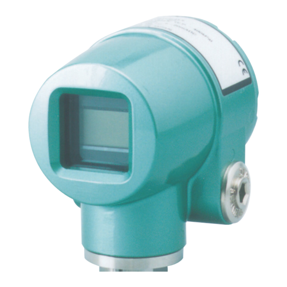
Figure 1-1 General view (front view) Housing Terminal Zero-adjustment terminal pin O-ring Case cover Grounding terminal Screw lock for cover detent Blind conduit plug Allen key Hole for mounting bracket Figure 1-2 General view (rear view) Model PTG60/70/71/72 - Smart Pressure Transmitter... - Page 18 Descriptions of Parts Azbil Corporation Flange Figure 1-3 Flange mount type, model PTG__F Ferrule Figure 1-4 Ferrule mount for sanitary type, model PTG__S Model PTG60/70/71/72 - Smart Pressure Transmitter...
- Page 19 Azbil Corporation Descriptions of Parts Mounting bracket U-bolt for mounting 2-inch pipe Figure 1-5 Mounting bracket (optional) for screw mount type Model PTG60/70/71/72 - Smart Pressure Transmitter...
- Page 20 Descriptions of Parts Azbil Corporation Model PTG60/70/71/72 - Smart Pressure Transmitter...
-
Page 21: Chapter 2 : Installation
Install this device in such a way that water will not enter the air inlet and powder or viscous materials will not be deposited on it. Air inlet When the air inlet fitting is attached Fitting for air inlet (chloroprene rubber, included with the product) Figure 2-1 Model PTG60/70/71/72 - Smart Pressure Transmitter... -
Page 22: Installing Screw-Mount Transmitters (Model Ptg
Establish a tap on top of or alongside the line and install the Transmitter process line. Establish a tap alongside the process line and install the Transmitter beneath that tap to allow condensation to return through the connecting pipe. Model PTG60/70/71/72 - Smart Pressure Transmitter... - Page 23 Install the Transmitter in a location where the liquid process does not freeze. • • or an equivalent pressure may be applied. Do not screw the Transmitter into a Sealing tape Figure 2-2 Installation precaution 1 Model PTG60/70/71/72 - Smart Pressure Transmitter...
- Page 24 Vertical connection Screwing on the transmitter with the connecting pipe filled with liquid will damage the transmitter. Be sure to establish a vapor phase portion. Figure 2-3 Installation precaution 2 Model PTG60/70/71/72 - Smart Pressure Transmitter...
-
Page 25: Direct Mounting Onto The Process Line
• The method of connecting the Transmitter to the process line must be appropriate for each given process. • Liquid Figure 2-4 An example of the direct-mount method Model PTG60/70/71/72 - Smart Pressure Transmitter... -
Page 26: Installing Using An Optional Mounting Bracket
• process. • The pressure outlet should be in a place that is free from unnecessary dynamic pressure. Also, install this device so that the impulse pipe between the pressure outlet and • Model PTG60/70/71/72 - Smart Pressure Transmitter... - Page 27 B: The PTG is installed above the pressure outlet. Main valve, Gauge valve Air release valve, Drain valve Black part of The desirable direction of the pressure outlet Figure 2-5 Pressure output direction and method of connecting impulse pipes Model PTG60/70/71/72 - Smart Pressure Transmitter...
- Page 28 Installation Azbil Corporation Installing the transmitter on a panel Figure 2-6 Installing the transmitter with the mounting brackets on a panel and 2-inch pipe Model PTG60/70/71/72 - Smart Pressure Transmitter...
- Page 29 Azbil Corporation Installation Figure 2-7 Dimensions of mounting bracket Model PTG60/70/71/72 - Smart Pressure Transmitter...
-
Page 30: Safety Precautions
After the Transmitter is installed, do not use it as a foothold or any other improper • digital indicator. • temperature of the Transmitter very high. • connection. Installation precautions • • could lead to a major accident. • • • • • 2-10 Model PTG60/70/71/72 - Smart Pressure Transmitter... -
Page 31: Handling Precautions
• Install the Transmitter in a location where liquid process does not freeze. • • After installing the transmitter, adjust the zero point. Model PTG60/70/71/72 - Smart Pressure Transmitter 2-11... -
Page 32: Precautions
Installation Azbil Corporation Precautions • and possible vibration. • Connect the conduit to satisfy the given process requirements. Flange mount type transmitter, PTG__F Flange Gasket Flange Figure 2-8 2-12 Model PTG60/70/71/72 - Smart Pressure Transmitter... -
Page 33: Installing Ferrule-Mount (Sanitary Type) Transmitters (Model Ptg
Transmitter side by side with or to the upper side of the nozzle so that the process returns to the process piping. downside of the nozzle so that the condensed water collects in the conduit piping. Model PTG60/70/71/72 - Smart Pressure Transmitter 2-13... -
Page 34: Handling Precautions
The use of standard models in the following installation locations may cause of resistance to dynamic pressure or resistance to pulsation. [Recommended locations for dynamic pressure resistant model] process [Recommended locations for pulsation resistant model] • After installing the transmitter, adjust the zero point. 2-14 Model PTG60/70/71/72 - Smart Pressure Transmitter... -
Page 35: Mounting Of Sanitary Type Transmitters
The pressure outlet should be in a place that is free from unnecessary dynamic pressure. Example of mounting Sanitary type transmitter, PTG__S Ferrule flange Clamp (not included) Gasket (not included) Ferrule flange Pipe Figure 2-9 Example of mounting sanitary type transmitter Model PTG60/70/71/72 - Smart Pressure Transmitter 2-15... - Page 36 Azbil Corporation 2-16 Model PTG60/70/71/72 - Smart Pressure Transmitter...
-
Page 37: Chapter 3 : Wiring
Azbil Corporation Wiring Chapter 3 : Wiring Wiring precautions CAUTION • malfunction of the product. • will cause a damage to the product. • The product is designed based on a two-wire wiring system. The power supply line also functions as a signal line. The wires are routed through the conduit hole on the side face of the Transmitter and are connected to the terminals. - Page 38 Wiring Azbil Corporation • Sample alarm system configuration (Hazardous area) (Non-hazardous area) Alarm equipment Power Lamp, display, buzzer, LED, supply sound, communication display, etc. Electric transmission equipment 4-20mA DC Recorder Indicator, etc. For FM and NEPSI Explosion-proof wiring WIRING PRECAUTIONS must comply with the method shown below.
-
Page 39: Wiring Diagram
Azbil Corporation Wiring Wiring diagram SUPPLY ZERO Receiving instrument (power supply) 250 Ω * A. Connection to a receiving instrument with a built-in power supply Power supply SUPPLY ZERO Receiving instrument 250 Ω * *: A load resistance greater than 250 is required for communicator. -
Page 40: Power Supply And External Load Resistance
Wiring Azbil Corporation Power supply and external load resistance supply so that both fall inside the diagonally-shaded area below. Transmitter, which includes the resistance in the cables forming the loop, the internal resistance in instruments connected between the Transmitter and the power supply, etc. -
Page 41: Chapter 4 : Calibration
Azbil Corporation Calibration Chapter 4 : Calibration point calibration is complete. That is, only one zero-point adjustment is needed for a complete calibration. Zero adjustment Calibration procedure Connect the power supply to the Transmitter. atmospheric pressure. This product has two zero adjustment terminal pins. - Page 42 Calibration Azbil Corporation Model PTG 60/70/71/72 - Smart Pressure Transmitter...
-
Page 43: Chapter 5 : Maintenance And Troubleshooting
Are the readings correct for power source voltage and load resistance? • Is there any sediments or foreign objects at the wetted part? • Is there dirt or debris present, clogging the connecting pipe? Is the gate valve fully open? Model PTG60/70/71/72 - Smart Pressure Transmitter... -
Page 44: Over-Range Alarm Display
Maintenance and troubleshooting Azbil Corporation Over-range alarm display When the input pressure from the process meets the following conditions, the digital Example of over-range alarm display (blinking) Model PTG60/70/71/72 - Smart Pressure Transmitter... -
Page 45: Chapter 6 : Operation With Field Communication Software (Cfs100)
If you remove the communications cable to change the device during this communication, an error will occur. communications cable to the new device. sure to switch the process control loop to manual mode beforehand. Model PTG60/70/71/72 - Smart Pressure Transmitter... -
Page 46: Menu List
Operation with Field Communication software (CFS100) Azbil Corporation 6-2 : Menu List are parameters that can be changed. Model PTG60/70/71/72 - Smart Pressure Transmitter... - Page 47 AO Alarm Type *2 *6 Loop Test *6 D/A Trim *6 Scaled D/A Trim *6 Output Limit *2 *3 *6 HART Output *2 Poll Address *2 Num Req Preams *2 Fail Safe Direction *7 Loop Test *7 Model PTG60/70/71/72 - Smart Pressure Transmitter...
- Page 48 Basic Setup Damping time constant, check or set Damping Units of pressure, check or change Pressure Unit Zero adjustment, execute Apply value Loop test, execute Loop Test Indicator, set Display Maintenance Calibrate Correct Input Model PTG60/70/71/72 - Smart Pressure Transmitter...
- Page 49 This section explains how to input or change the tag No. In the menu tree in the left pane, select DEVICE SETUP DETAILED SETUP Device Information Tag. send the new Tag to the pressure transmitter. Send Model PTG60/70/71/72 - Smart Pressure Transmitter...
-
Page 50: Display Format
Indicates that both the output and the displayed values are linear and equal to scale readings. % (Linear) Indicates that both the output and the displayed values are linear and in percent figures. EULO/EUHI (upper and lower limits for engineering units) Model PTG60/70/71/72 - Smart Pressure Transmitter... -
Page 51: Selecting A Unit Of Pressure
This function allows you to select the measurement units for pressure used by the reconnection, measurements are displayed in the default units for pressure, that Select DEVICE SETUP BASIC SETUP Pressure Unit. inH2O inHg mmH2O mmHg mbar g/Sqcm kg/Sqcm Model PTG60/70/71/72 - Smart Pressure Transmitter... - Page 52 Operation with Field Communication software (CFS100) Azbil Corporation This section explains how to configure the measurement range of the pressure transmitter. Select DEVICE SETUP BASIC SETUP Range Values. decimal places. does not change. Model PTG60/70/71/72 - Smart Pressure Transmitter...
- Page 53 PV Damp. The following values can be input. If a value other than the following is input, the closest value is automatically selected. Unit: sec. 0.16 0.32 0.48 1.00 2.00 4.00 8.00 16.0 32.0 Model PTG60/70/71/72 - Smart Pressure Transmitter...
- Page 54 Operation with Field Communication software (CFS100) Azbil Corporation NVM Save after it is sent to the pressure transmitter. If the pressure transmitter power is 6-10 Model PTG60/70/71/72 - Smart Pressure Transmitter...
-
Page 55: Preparations And Starting Operation
Caution: If this operation is performed while the pressure transmitter process is under automatic control, outputs may fluctuate, making pressure transmitter operation dangerous. Before performing this operation, make sure that you switch the process control loop to manual control. Model PTG60/70/71/72 - Smart Pressure Transmitter 6-11... - Page 56 Operation with Field Communication software (CFS100) Azbil Corporation • normal output mode will resume. • HART communication normal output mode will resume. 6-12 Model PTG60/70/71/72 - Smart Pressure Transmitter...
-
Page 57: Pressure
The range is reconfigured so that the current input pressure becomes the 4 mA output pressure (zero adjustment). • The range is reconfigured so that the current input pressure becomes the 20 mA output pressure (span adjustment). • Model PTG60/70/71/72 - Smart Pressure Transmitter 6-13... -
Page 58: Maintenance
CAUTION: If this operation is performed while the pressure transmitter process is under automatic control, outputs may fluctuate, making pressure transmitter operation dangerous. Before performing this operation, make sure that you switch the process control loop to manual control. 6-14 Model PTG60/70/71/72 - Smart Pressure Transmitter... - Page 59 No and click OK. This allows the adjustment process to continue. Finally, a message is displayed notifying you that this will return operation to normal measurement mode and that the 20 mA calibration process is complete. Model PTG60/70/71/72 - Smart Pressure Transmitter 6-15...
-
Page 60: Measurement Range Calibration According To Actual Pressure
Select DEVICE SETUP DIAG/SERVICE Calibration Correct Input. • • A warning that the loop should be switched from automatic control to manual • • • 6-16 Model PTG60/70/71/72 - Smart Pressure Transmitter... - Page 61 Before performing this operation, make sure that you switch the process control loop to manual control. • switched from automatic control to manual mode. After switching to manual • • • Model PTG60/70/71/72 - Smart Pressure Transmitter 6-17...
-
Page 62: Checking Self-Diagnostic Messages
Operation with Field Communication software (CFS100) Azbil Corporation Checking Self-diagnostic Messages calibrated values are reset. transmitter. 6-18 Model PTG60/70/71/72 - Smart Pressure Transmitter... -
Page 63: Chapter 7 : Operational Manual For Hart Communication (For Model Ptg72)
Instructions for connecting HART® Communicator to this transmitter. 7-1 : Connecting Communicator Power supply SUPPLY ZERO Receiving instrument 250 W * *: A load resistance greater than 250 is required for communicator. Figure 7-1 HART Communicator connection Model PTG60/70/71/72 - Smart Pressure Transmitter... -
Page 64: Hart Communicator Menu Summary
12 AO Alarm Type 13 Sensor Serial Number 14 PROM ID 5 REVIEW 15 Device ID 16 Tag 17 Message 18 Universal Rev 19 Field Device Rev 20 Software Rev 21 Poll Address 22 Num Req Preams Model PTG60/70/71/72 - Smart Pressure Transmitter... -
Page 65: Display Type
7-4 : Indicator Display Format PTG: TAG001 Meter Type 1 Display type EULO EUHI HELP SAVE HOME EXIT Display Type Mode Description EULO / EUHI with an engineering unit. Over Range Model PTG60/70/71/72 - Smart Pressure Transmitter... -
Page 66: Selecting Unit Of Measurement
3 PV LRL 4 PV URL HELP SAVE HOME EXIT PTG: TAG001 Range Values 1 PV LRV 0.000 inH2O 2 PV URV 5.000 inH2O 3 PV LRL 4 PV URL HELP SEND HOME EXIT Model PTG60/70/71/72 - Smart Pressure Transmitter... -
Page 67: Adjusting Damping Time
7-7 : Adjusting Damping Time PTG: TAG001 PV damping 0.5 s Value out of range HELP ENTER value is out of range. ATTENTION The damping time set by HART Communicator might not be corresponding to that Model PTG60/70/71/72 - Smart Pressure Transmitter... - Page 68 Azbil Corporation Model PTG60/70/71/72 - Smart Pressure Transmitter...
-
Page 69: Chapter 8 : Start-Up And Operation
Then, the following screen is appeared. PTG: TAG001 Choose analog output level 1 4mA 2 20mA 3 Other 4 End ABORT ENTER • • • values. • • returning transmitter to its original output. Model PTG60/70/71/72 - Smart Pressure Transmitter... - Page 70 Then the following screen will be appeared. PTG: TAG001 Set the: 1 4mA 2 20mA 3 Exit ABORT ENTER • Return the loop to automatic. Model PTG60/70/71/72 - Smart Pressure Transmitter...
-
Page 71: Chapter 9 : Calibration
CAUTION may vary, resulting in a hazardous operation status. this operation. STEP Action/Description When prompt appears, connect a precision milliammeter or volt meter • • • Model PTG60/70/71/72 - Smart Pressure Transmitter... - Page 72 Calibration Azbil Corporation • • • output. Model PTG60/70/71/72 - Smart Pressure Transmitter...
-
Page 73: Calibrating The Set Range By Inputting The Actual Pressure
The calibration must be conducted in a testing laboratory where there is no wind. • • It is best if the accuracy of the measuring instruments to be four times greater than that of the Transmitter. Model PTG60/70/71/72 - Smart Pressure Transmitter... -
Page 74: Assembling The Calibration Devices
Calibration Azbil Corporation Assembling the calibration devices Reference pressure generator HART Communicator Transmitter power supply Communication Standard resistor cable Voltmeter Figure 9-1 Wiring and piping for the calibration devices Model PTG60/70/71/72 - Smart Pressure Transmitter... - Page 75 PTG: TAG001 Correct Input 1 Zero Trim 2 Correct Input LRV 3 Correct Input URV 4 Reset Corrects HELP SEND HOME EXIT • • • • • When prompted, remove pressure. Model PTG60/70/71/72 - Smart Pressure Transmitter...
-
Page 76: Resetting Calibration
A Corrects Rest returns the zero and span calibration factors to their default values. The transmitter calculates its output based on the characterization equation alone, without any compensation for the residual errors. • • • • Calibration is reset to default values. • Model PTG60/70/71/72 - Smart Pressure Transmitter... -
Page 77: Chapter 10 : Spare Parts
Azbil Corporation Spare Parts Chapter 10 : Spare Parts Screw size (M4 x 8) Figure 10-1 Exploded view Table 10-1 Spare parts Parts description Part number Qty. Unit O-ring Model PTG60/70/71/72 - Smart Pressure Transmitter 10-1... - Page 78 Spare Parts Azbil Corporation 10-2 Model PTG60/70/71/72 - Smart Pressure Transmitter...
- Page 80 Warranty period and warranty scope 1.1 Warranty period Azbil Corporation’s products shall be warranted for one (1) year from the date of your purchase of the said products or the delivery of the said products to a place designated by you.
- Page 81 Although acceleration of the above situation varies depending on the conditions or environment of use of the products, you are required not to use any Azbil Corporation’s products for a period exceeding ten (10) years unless otherwise stated in specifications or instruction manuals.
- Page 83 Document Number: CM2-PTG100-2001 Document Name: Smart Pressure Transmitter Model PTG60/70/71/72 User’s Manual Date: 1st edition: Oct. 1998 7th edition: Apr. 2021 Issued/Edited by: Azbil Corporation...
Need help?
Do you have a question about the PTG60 and is the answer not in the manual?
Questions and answers