Sign In
Upload
Manuals
Brands
Azbil Manuals
Transmitter
MagneW Plus+ MGG14C
Azbil MagneW Plus+ MGG14C Manuals
Manuals and User Guides for Azbil MagneW Plus+ MGG14C. We have
2
Azbil MagneW Plus+ MGG14C manuals available for free PDF download: User Manual
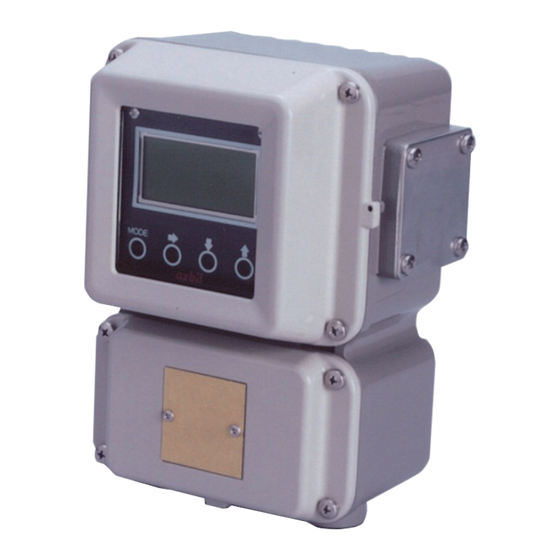
Azbil MagneW Plus+ MGG14C User Manual (146 pages)
Electromagnetic Flowmeter Converter
Brand:
Azbil
| Category:
Media Converter
| Size: 11 MB
Table of Contents
Table of Contents
7
Chapter 1: Introduction
13
Flex+/Plus
13
Main Components
13
Figure 1-1 Integral System
13
Figure 1-2 Remote System
14
Analog Output and Digital Output
15
System Configuration for Analog Output (4 to 20 Ma DC Output)
16
System Configuration WITHOUT the Communication Function
17
Figure 1-3 System Configuration of Analog Output WITHOUT Communication Function
17
System Configuration with the HART Communication Function with the Internal Power Supply
18
Figure 1-4 System Configuration of with the HART Communication with Internal Power Supply
18
System Configuration with the SFC or HART Communication Function with the External Power Supply
19
Figure 1-5 System Configuration for Analog Output with the Communication Function (Example Setup)
19
System Configuration for Digital Output (de Output)
20
System Configuration
20
Figure 1-6 System Configuration for Digital Output
20
Figure 1-7 Parts of the Converter
21
Approval of this Device
22
Figure 1-8 System Configuration
23
Chapter 2: Installation
25
Site Selection
25
Unpacking and Storage
26
Installation Options
27
Figure 2-1 Integral Installation
27
Figure 2-2 Wall Mounted Remote Installation
27
Changing the Orientation of the Converter
28
Figure 2-3 Pipe Mounted Remote Installation
28
Wiring
29
Integral Wiring - 1 (1-Contact Input and 1- Contact Output)
30
Figure 2-4 Integral Converter Terminal Block
30
Table 2-1 Remote Converter Terminal Descriptions (1-Contact Input & 1-Contact Output)
30
Integral Wiring - 2 (2-Contact Input)
31
Figure 2-5 Integral Converter Terminal Block
31
Table 2-2 Remote Converter Terminal Descriptions (2-Contact Input)
31
Integral Wiring - 3 (2-Contact Output)
32
Figure 2-6 Integral Converter Terminal Block
32
Table 2-3 Remote Converter Terminal Descriptions (2-Contact Output)
32
Remote Wiring - 1 (1-Contact Input and 1- Contact Output)
33
Figure 2-7 Remote Converter Terminal Block
33
Table 2-4 Remote Converter Terminal Descriptions (1-Contact Input & 1-Contact Output)
33
Remote Wiring - 2 (2-Contact Input)
34
Figure 2-8 Remote Converter Terminal Block
34
Table 2-5 Remote Converter Terminal Descriptions (2-Contact Input)
34
Remote Wiring - 3 (2-Contact Output)
35
Figure 2-9 Remote Converter Terminal Block
35
Table 2-6 Remote Converter Terminal Descriptions (2-Contact Output)
35
Figure 2-10 Cable Usage Ranges
36
Grounding
36
Signal and Excitation Cable Specifications
36
Figure 2-11 Signal Cable Dimensions
37
Figure 2-12 Excitation Cable Dimensions
37
Figure 2-13 Signal and Excitation Cable Construction
37
Signal and Excitation Cable Wiring
38
Figure 2-14 Detector to Converter Wiring Diagram
38
Wiring Cable
39
Wiring
40
Figure 2-15 Wiring Diagram for Current Output
40
Figure 2-16 Wiring Diagram for Pulse Output
41
Figure 2-17 Switch Locations on Main Card
41
Figure 2-18 Wiring Diagram for Contact Input
42
Figure 2-19 Wiring Diagram for Contact Output
42
Setting Write Protection
43
Table 2-7 Write Protection Levels
43
Figure 2-20 Switch Locations on Main Card
44
Figure 2-21 Write Protection Switch Positions
44
Setting the Communication Via the HART
45
Figure 2-22 Switch Locations on Main Card
45
Figure 2-23 HART Communication Switch Positions
45
Setting the Empty Detection Function
46
Figure 2-24 Switch Locations on Main Card
46
Figure 2-25 Empty Detection Function Switch Positions
46
Setting the Communication Via the SFC
47
Figure 2-26 Switch Locations on Main Card
47
Figure 2-27 SFC Communication Switch Positions
47
Connecting Power
48
Figure 2-28 Name Plate
48
Chapter 3: Operation
49
Start-Up
49
Shut down
49
Figure 3-1 Start-Up Display
49
Figure 3-2 Display Panel
50
Figure 3-3 Touch Sensor Keys
51
Figure 3-4 Using the Touch Sensor Keys
51
Table 3-1 Touch Sensor Key Functions
52
Table 3-2 Default Settings
53
Using the Display Panel
55
Chapter 4 : Using the Display Panel
55
About Modes
55
Table 4-1 Mode Functions
56
Measuring Mode
58
LCD Display Flow
59
Entering BASIC SETUP MODE
65
Setting the TAG no
66
Default Setting
66
Setting Range
66
Damping Time Constant
67
Default Setting
67
Setting Range
67
Auto Zero
68
Flow Counter - Reset Value
70
Flow Counter - Resetting
71
Detector Data
72
Default Setting
72
Setting the Number of Dummy Detectors
74
Default Setting
74
Setting Range
74
Flow Rate Range
75
Setting Range
75
Flow Rate Indication
76
Default Setting
76
Setting Range
76
Entering ENGINEERING / ADVANCED / MAINTENANCE MODE
77
Entering ENGINEERING MODE
77
Entering ADVANCED MODE
77
Entering MAINTENANCE MODE
78
Selecting Functions
79
Relations for Setting Function FXXXX
81
Range Functions
84
Single Range
84
Figure 4-1 Single Range
84
Normal Direction Automatic Dual Range
85
Figure 4-2 Normal Direction Automatic Dual Range
85
Normal Direction, External Switching Dual Range
86
Normal/Reverse Automatic Switching Range
87
Figure 4-3 Normal/Reverse Automatic Switching Range
87
[Built-In Counter Function]
89
[Contact Input Function]
90
[Contact Output Function]
91
Table 4-2 Output Selection
91
Figure 4-4 2-Stage Flow Rate Alarm Output
93
Flow Rate Range
94
Setting Range
94
Setting Hysteresis
96
Selecting the Current Output Method for Dual Range
97
Figure 4-5 Selecting the Current Output Method for Dual Range
97
Setting / Changing the Preset Value of the Built-In Flow Counter
98
Specific Gravity
99
Pulse Weight
100
Setting the Pulse Width
101
Setting High and Low Limit Alarms
103
Setting a 2-Stage Flow Rate Alarm
104
Selecting Fail-Safe Mode for the Analog Output
106
Default Setting
106
Setting Range
106
Selecting Fail-Safe Mode for the Pulse Output
107
Default Setting
107
Setting Range
107
Setting the Contact Output Status
108
Damping Time Constant
110
Default Setting
110
Setting Range
110
Manual Zeroing
111
Important
111
How to Set
111
Setting Moving Average
112
Default Setting
112
Setting Range
112
Auto Spike Cut Function
114
Default Setting
114
Manual Spike Cut Function
115
Default Setting
115
Setting Range
115
Coefficient of Compensation
116
Setting the Drop-Out
117
Setting the Low Flow Cut
118
Setting Decimal Place
119
Change the Excitation Frequency
120
Setting the Analog Output Limit
121
Change the Flow Direction
122
Error History Check/Clear
123
Chapter 5: Maintenance and Troubleshooting
125
Function Check
126
Input and Output Signal Loop Check
126
Analog Output Check
127
Default Setting
127
Setting Range
127
Pulse Output Check
128
Default Setting
128
Setting Range
128
Contact Input/Output Loop Check
129
Default Setting
129
Setting Range
129
Excitation Current Check
132
Simulated Signal by the Calibrator
133
Preparation
133
Troubleshooting
134
Errors at Startup
135
Table 5-1 Startup Errors
135
Operation Errors
136
Table 5-2 Operation Errors
136
Error Messages
137
Error Codes for Critical Problems
137
Table 5-3 Critical Errors
137
Error Codes for Non-Critical Problems
138
Table 5-4 Non-Critical
138
Safety Precautions
139
Operating Precautions
139
Examples of Symbol
139
Structure and Functions of SFC
140
Advertisement
Azbil MagneW Plus+ MGG14C User Manual (110 pages)
Electromagnetic Flowmeter Foundation Fieldbus Transmitter
Brand:
Azbil
| Category:
Transmitter
| Size: 3 MB
Table of Contents
Table of Contents
7
1 Introduction
9
System Configuration
9
Foundation Fieldbus
10
Main Components
12
Local User Interface
13
2 Overview of Magnew PLUS+ F Oundation Fieldbus
21
Overview
21
Structure of Magnew PLUS+ Foundation Fieldbus
21
System/Network Management VFD
21
Function Block VFD
22
Function Block
22
Transducer Block
22
Vfd/Object Correlation Diagram
23
Wiring
24
Others
25
3 Installation
27
Before Installing Electromagnetic Flowmeter
28
Installation of Transmitter
29
4 Startup and Shutoff
37
Startup
37
Steps before Measurement
38
Shutoff
41
5 Basic Settings by Fieldbus Communication
43
Fieldbus Communication Menu
44
Zero Adjustment
45
Basic Settings
46
6 Maintenance and Troubleshooting
59
Troubleshooting
59
Input of Simulated Signals from Calibrator
64
Measurement of Excitation Current
65
Appendix A. View List
69
Appendix B. Parameter List
79
Appendix C. Menu Configuration
97
Advertisement
Related Products
Azbil MagneW FLEX+/PLUS+ MGG10C
Azbil MGG15
Azbil MGG17
Azbil MGG11
Azbil MGG19
Azbil MGG18
Azbil MGG12
Azbil MGF11
Azbil MGS11U
Azbil MGR13C
Azbil Categories
Controller
Control Unit
Measuring Instruments
Transmitter
Security Sensors
More Azbil Manuals
Login
Sign In
OR
Sign in with Facebook
Sign in with Google
Upload manual
Upload from disk
Upload from URL