
Related Manuals for Azbil JTD910S


Summary of Contents for Azbil JTD910S
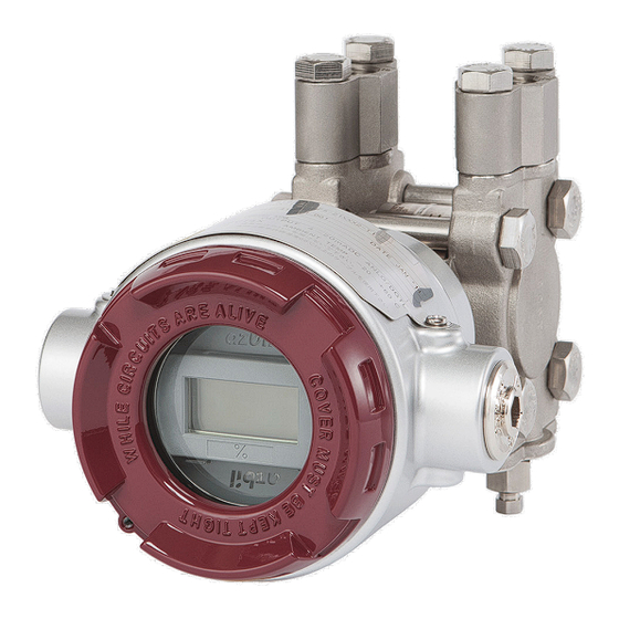
- Page 1 CM2-ATS100-2001 Advanced Differential Pressure and Pressure Transmitter Model JTD/JTG/JTA/JTC/JTE/JTH/JTS User's Manual...
- Page 2 Please understand that we cannot in some cases accept responsibility for the results of use of this equipment by the customer. • HART® is a registered trademark of FieldComm Group. © 2014-2022 Azbil Corporation. All Rights Reserved.
- Page 3 Introduction Introduction Thank you for purchasing an Azbil advanced transmitter series. Structure of this Series This series has the following models and model number configuration. Differential Gauge Pressure Absolute Flange Type Pressure Transmitters Gauge Pressure Differential Transmitters Transmitters Pressure Transmitters...
- Page 4 Introduction Usage Precautions Introduction In order to use this product safely, it is essential to install and operate it correctly, and to carry out periodic maintenance. Please read and understand the safety precautions described in this operation manual carefully before carrying out installation, operation, and maintenance.
- Page 5 Introduction Product Usage Precautions Usage Limitations and Requests This product was designed, developed, and manufactured under the assumption that it would be used as a general-purpose model and as an explosion-proof model. Do not use this product for applications in which its operation directly affects human life, or for nuclear energy applications in radiation controlled areas. For applications such as ...
- Page 6 Introduction Wiring Precautions Caution Do not perform wiring work, turn on the electricity, etc., when your hands are wet. Also, do not perform hot swapping. There is a risk of electric shock. Do this work with dry hands or wearing gloves, and with the electricity turned off.
- Page 7 Introduction Communication Device Usage Precautions If communication devices such as transceivers, cellular phones, PHS phones, or pagers are used in the vicinity of this product, depending on the transmission frequencies being used there may cases in which the product does not function properly, so please observe the following precautions.
- Page 8 Introduction Product unpacking, verification, and storage Unpacking This product is a precision instrument. Handle it carefully in order to prevent accidents, injuries, etc. Verifying accessories Upon unpacking the product, verify that the main body and the following items have been included.
-
Page 9: Table Of Contents
Table of Contents Table of Contents Chapter 1 Functionality, Configuration, and Structure of this Device and CommStaff . .1-1 1-1 Functionality and Configuration of this Device ........1-1 1-1-1 Functionality and Configuration of this Device . - Page 10 Table of Contents 3-2-4 Sealed Tank (Wet Leg) Liquid Level Measurement ......3-18 3-3 Measurement Using the JTG/JTA Model .
- Page 11 Table of Contents A2-4-1 Preparation ............. .A-5 A2-4-2 Acquisition of index values under normal operating conditions .
- Page 12 Table of Contents...
-
Page 13: Chapter 1 Functionality, Configuration, And Structure Of This Device And Commstaff
Chapter 1 Functionality, Configuration, and Structure of this Device and CommStaff Chapter 1 Functionality, Configuration, and Structure of this Device and CommStaff This chapter describes the basic functionality, structure, and configuration of this device, as well as the basic functionality and configuration of CommStaff, the communicator required to operate this device. -
Page 14: Part Names
Chapter 1 Functionality, Configuration, and Structure of this Device and CommStaff 1-1-2 Part Names This device is composed primarily of a main unit, an electronics module, a terminal block with integrated indicators, a transmission unit case, and a case cover. The following diagram shows the structure and part names of this device. - Page 15 Chapter 1 Functionality, Configuration, and Structure of this Device and CommStaff • Main unit: Composed of a compound semiconductor sensor, an A/D circuit, a pressure-receiving diaphragm, an excess pressure protection mechanism, etc. • Cover flanges: Parts which sandwich the sides of the main unit to maintain pressure.
-
Page 16: Indicators (Optional)
Chapter 1 Functionality, Configuration, and Structure of this Device and CommStaff 1-1-3 Indicators (Optional) The names of the display indicators are as follows. Figure 1-5. Indicator Display Unit Table 1-1. Indicator Display Unit No . Indicator/Symbol Indicator Description Main indicator (4.5 digits) Process variable (engineering Value, error unit scale, real pressure), %... - Page 17 Chapter 1 Functionality, Configuration, and Structure of this Device and CommStaff (i) Main display indicators • When the display value is in the following range, the display limit value blinks. Display value range Blinking display value Display value < -19999 -19999 Display value >...
- Page 18 Chapter 1 Functionality, Configuration, and Structure of this Device and CommStaff (iv) External zero adjustment indicators If the (optional) external zero adjustment functionality is in effect, its operating status is displayed as follows. Table 1-3. External Zero Adjustment Operating Status Indicator Adjustment 16-Segment...
-
Page 19: Commstaff Functionality And Configuration
CommStaff, communication is carried out by connecting a communication interface to a USB port of a PC, and connecting a communication cable to a communication terminal of an Azbil smart device. CommStaff supports HART communication and Azbil's proprietary SFN communication. -
Page 20: Conditions For Connected Devices
Field Communication Software CommStaff User's Manual: CM2-CFS100-2001 (2) Communication Interface Use a communication module that meets the following conditions. CFS100 SFN DE Azbil product model number SFN/DE communication interface • 80345962-001 (alligator clip type) • 80345962-002 (easy hook type) MACTek VIATOR USB HART... -
Page 21: Chapter 2 Installation Of This Device
Chapter 2 Installation of this Device Chapter 2 Installation of this Device This chapter covers important points related to the installing this device and setting up its piping and wiring. Individuals in charge of installation work should read this chapter. 2-1 Installation Location Selection Criteria 2-1-1 General Installation Conditions (1) Introduction... - Page 22 Chapter 2 Installation of this Device • Temperature: Install the device in an area that satisfies the following temperature conditions. Ambient temperature JT _9 _ _ S with indicator: -20 - +55 °C JT _9 _ _ S without indicator: -20 - +60 °C JT _9 _ _W with indicator: -20 - +55 °C...
- Page 23 Chapter 2 Installation of this Device (3) Installation Criteria for Intrinsically Safe Explosion-Proof Models (Ex ia IIC T4 Ga, Ex ia IIIC T 105 °C Da) The following are the electric parameters for intrinsically safe explosion-proof models. • Electric parameters: Ui = 30 V, Ii = 93 mA, Pi = 1 W, Ci = 5 nF, Li = 0.6 mH The intrinsically safe explosion-proof models are for the following explosive gas and electrical equipment, and temperature class.
-
Page 24: Equipment Use Conditions
Chapter 2 Installation of this Device • Withstand voltage test This product does not satisfy the withstand voltage specifications required by the above standard. The conditions of the withstand voltage test are as follows: Applied between the supply terminal (+ and - terminals are connected) and the ground terminal in the terminal box Applied voltage: 500 V DC (specified in section 6.3.13 in Part 6 of the above standard) Applied for:... -
Page 25: Installation
Chapter 2 Installation of this Device 2-2 Installation 2-2-1 Installation Dimensions See the dimensions diagram (in the specifications sheet or delivery specifications) for this device. 2-2-2 Installation Location See the general installation conditions in 2-1-1. 2-2-3 Transmitter Body Installation (1) Components Required for Installation In order to install this device, have the following items ready. - Page 26 Chapter 2 Installation of this Device (iii) Installation precautions for pressure/differential pressure remote-sealed type of differential pressure transmitters • If the liquid fill is for high-temperature high-vacuum, the viscosity of the liquid fill will rise as the measured temperature and ambient temperature fall, and the response speed of the transmitter will slow down.
- Page 27 Chapter 2 Installation of this Device (iv) Considering locations at which to attach to the sealed tank When attaching the transmitter to a location that is higher than the lower flange of the sealed tank, the following conditions must be satisfied. When considering locations, assume that the tank is empty. Figure 2-4.
- Page 28 Chapter 2 Installation of this Device Table 2-1. Allowable Pressure Low Limit Example Sealed Liquid Allowable Pressure Contact Liquid Specific Gravity Low Limit Temperature Range ρ' P (kPa abs) °C General-purpose 0.935 -40 to +40 For high-temperature 1.07 -5 to +90 For high-temperature 1.07 0.133...
-
Page 29: Connecting The Wetted Part Of A Flange Type Or Remote Seal Type To The Process
Chapter 2 Installation of this Device 2-2-4 Connecting the Wetted Part of a Flange Type or Remote Seal Type to the Process Warning When installing the product, make sure that the gaskets do not stick out at the connections with the process (connections between adapter flanges and connecting pipes and flanges). Also be careful not to forget to close vent and drain plugs. - Page 30 Chapter 2 Installation of this Device (2) Precautions When Attaching the Pressure-Receiving Portion of a Remote Seal Type (JTE/JTH/JTS) Transmitter • For the JTE model, in order to lessen the effects of temperature differences in the surroundings, bundle together the high pressure side and low pressure side capillary tubes. In addition, fasten the capillary tubes so that they do not move around due to wind, vibration, etc.
- Page 31 Chapter 2 Installation of this Device (3) Precautions When Handling Capillary Tubes • When handling capillary tubes, be careful not to twist them. • When unwinding a capillary tube, hold the flange portion and turn the tube such that it reverts to a big loop.
-
Page 32: Precautions When Attaching Fep Protective Film
Chapter 2 Installation of this Device 2-2-5 Precautions When Attaching FEP Protective Film * The FEP protective film is optional. If this option is selected, a “Teflon Protective Film Attachment Manual” will be included, so refer to that document as well. •... - Page 33 Chapter 2 Installation of this Device (4) Press the film outward from the center of the diaphragm such that the grease sticks out from the periphery. Press slowly so no air remains between the diaphragm and the FEP protective film. Press the grease out until there is almost none left on the surfaces around the gasket. After pressing out 5-7 g of grease, the thickness of the grease on the diaphragm surface will be about 0.5 mm.
- Page 34 Chapter 2 Installation of this Device (5) Place the gasket against the flange of the pressure-receiving part, and attach it to the process flange. The tightening torque for the bolts and nuts is shown in Table 2-2. During bolt tightening, apply an equal amount of tightening torque to each bolt. Figure 2-13.
-
Page 35: Fit-Tank Attachment (Jte Model)
Using Fit-Tank alleviates the need to attach the transmitter body to a stanchion. In addition, Azbil's proprietary sealed liquid temperature compensation feature and capillary tubes, which are included standard with the remote seal type transmitter, can be wired in a methodical manner, and satisfactory temperature characteristics can be attained. - Page 36 Chapter 2 Installation of this Device (2) Attachment Overview (i) Attachment dimensions Figure 2-18 shows the adapter assembly attached to the process side, and Figure 2-19 shows the appearance and length of the adapter in the attachment kit. Protective Pipe Remote Seal Type Di erential Pressure Transmitter Adapter...
- Page 37 Chapter 2 Installation of this Device (2) Attachment of the transmitter side flange only to the process side flange First, attach the desired transmitter side flange to the process side flange. For information regarding flange attachment, see section 2-2-4. The transmitter can be attached to either the high pressure or low pressure flange.
- Page 38 Chapter 2 Installation of this Device Caution If a capillary tube, bent back as shown in Figure 2-24, is placed higher than the lower flange of the process, the tank internal pressure must be at least as high as the atmospheric pressure.
- Page 39 Chapter 2 Installation of this Device Figure 2-24. Attachment Example (2) * For attachment to a sealed tank, see section 2-2-3(2) "(iv) Considering locations at which to attach to the sealed tank" 2-19...
-
Page 40: 1/2B Remote Attachment (Jte/Jth Model)
Chapter 2 Installation of this Device 2-2-7 1/2B Remote Attachment (JTE/JTH Model) (1) Attachment Overview (i) Attachment dimensions Figure 2-25 shows an assembly dimensions diagram. (Unit: mm) Figure 2-25. 1/2B Remote Adapter Assembly Diagram and Dimensions (ii) Attachment method (1) 1/2B remote adapter attachment check Confirm that the pressure-receiving parts at the ends of the capillary tubes and the adapter are securely fastened together using four sets of bolts and nuts. - Page 41 Chapter 2 Installation of this Device (2) Attachment to process side flanges Figure 2-26 shows an example of attachment to the tank. For information regarding flange attachment, see section 2-2-4. The minimum bending diameter of the capillary tubes should be about 5 cm.
-
Page 42: To A Flanged Transmitter (Models Jte, Jth, Jts, And Jtc)
Chapter 2 Installation of this Device 2-2-8 Installation of the Flushing Ring (Model DV) to a Flanged Transmitter (Models JTE, JTH, JTS, and JTC) (1) Function and structure This chapter describes the function and configuration of the optional flushing ring for the remote seal type and flange type transmitters. - Page 43 Chapter 2 Installation of this Device (2) Installing Instructions This section explains the installation of the flushing ring, piping method and other important matters. In order to properly use the flushing ring, install it according to the conditions described below. (i) Installation site selection Choose the location of the flushing ring according to the following conditions.
- Page 44 Chapter 2 Installation of this Device Install the transmitter and flushing ring according to Figure 2-29. • Be sure to install the flushing ring so that the vent/drain plugs are in a vertical position. • Prepare the correct size parts (threaded rods, nuts, gaskets) according to the process flange. Consider the port diameter, pressure rating, operating temperature, etc.
- Page 45 Chapter 2 Installation of this Device (3) Precautions When Using the Vent/Drain Plug The vent/drain valve consists of the vent/drain plug and vent/drain bushing. Here are some precautions when using this valve. Loosen vent/drain plug to release pressure or to drain Metal seal surface DO NOT loosen tapered thread Figure 2-30.
-
Page 46: Piping
Chapter 2 Installation of this Device 2-3 Piping 2-3-1 Flow Rate Measurement Piping (JTD Model) Warning When doing the piping work, ensure that the connections between the connecting pipe parts and the transmitter and three-way manifold valve are able to maintain a reliable seal. - Page 47 Chapter 2 Installation of this Device (ii) High pressure side display on this device An “H” is displayed on the high pressure side of the main unit of this device to indicate high pressure, so be sure to check this during piping in order to avoid mistakes. The side without a mark is the low pressure side.
- Page 48 Chapter 2 Installation of this Device (2) Liquid or Gas Flow Rate Measurement Piping (i) Example of recommended piping for liquid flow rate measurement A typical piping example in which the device is lower than the differential pressure output port on the process pipe.
- Page 49 Chapter 2 Installation of this Device (ii) Recommended piping, example 2 A typical piping example in which the device is higher than the differential pressure output port of the process pipe is shown below. Be sure to implement the following items. •...
- Page 50 Chapter 2 Installation of this Device (3) Vapor Flow Rate Measurement Piping (i) Recommended piping example A typical piping example is illustrated below. With this vapor flow rate measurement piping, the device is installed lower than the differential pressure output port. Be sure to implement the following items.
-
Page 51: Pressure Measurement Piping (Jtd/Jtg/Jta Model)
Chapter 2 Installation of this Device 2-3-2 Pressure Measurement Piping (JTD/JTG/JTA Model) Warning When doing the piping work, ensure that the connections between the connecting pipe parts and the transmitter and three-way manifold valve are able to maintain a reliable seal. - Page 52 Chapter 2 Installation of this Device (2) Pressure Measurement Piping (i) Recommended piping example A typical pressure measurement piping example is illustrated below. Be sure to implement the following items. • Depending on the measured fluid, create an incline in the differential pressure output pipes so that drains, vents, etc., will clear.
- Page 53 Chapter 2 Installation of this Device (ii) Piping method The piping method differs depending on the state of the measured fluid, indicator location, pipeline, etc. A typical piping example is illustrated below. Run the piping as shown below. Master Valve Master Valve Process Process...
-
Page 54: Liquid Level Measurement Piping (Jtd/Jtg Model)
Chapter 2 Installation of this Device 2-3-3 Liquid Level Measurement Piping (JTD/JTG Model) Warning When doing the piping work, ensure that the connections between the connecting pipe parts and the transmitter and three-way manifold valve are able to maintain a reliable seal. - Page 55 Chapter 2 Installation of this Device (iv) Selection of pipes For connecting pipes from the process, select pipe schedule numbers and nominal thicknesses in accordance with process side selection criteria (conditions such as process pressure). Diameter 1/2B, schedule number 80 steel pipes are one example of connecting pipes which are commonly used.
- Page 56 Chapter 2 Installation of this Device (2) Open Tank Piping (i) Recommended piping example A typical open tank liquid level piping example is illustrated below. Be sure to implement the following items. • Connect the high pressure side of the device to the lower portion of the tank, and open the low pressure side to the atmosphere.
- Page 57 Chapter 2 Installation of this Device (3) Sealed Tank Piping (i) Dry leg recommended piping example A typical sealed tank dry leg liquid level piping example is illustrated below. Be sure to implement the following items. • Connect the high pressure side of the device to the lower portion of the tank, and connect the low pressure side to the tank's gas seal pipe.
- Page 58 Chapter 2 Installation of this Device (ii) Wet leg recommended piping example A typical sealed tank wet leg liquid level piping example is illustrated below. Be sure to implement the following items. • Connect the high pressure side of the device to the tank's liquid seal piping, and connect the low pressure side to the lower portion of the tank.
-
Page 59: Liquid Level Measurement Piping (Jtc Model)
Chapter 2 Installation of this Device 2-3-4 Liquid Level Measurement Piping (JTC Model) Warning When doing the piping work, ensure that the connections between the connecting pipe parts and the transmitter and three-way manifold valve are able to maintain a reliable seal. - Page 60 Chapter 2 Installation of this Device (2) Open Tank Piping (i) Recommended piping example A typical open tank liquid level piping example is illustrated below. Since the high pressure side is attached directly to the nozzle on the lower portion of the tank, a connecting pipe will normally not be necessary.
-
Page 61: Electrical Wiring
Chapter 2 Installation of this Device 2-4 Electrical Wiring 2-4-1 General Wiring (1) Introduction Wiring which is not subject to explosion-proofing standards will now be described. When working with explosion-proof wiring, in addition to the description here, see section 2-4-2, “Explosion-Proof Wiring. ” (2) Wiring When wiring, refer to the following diagram. - Page 62 Chapter 2 Installation of this Device (3) Caution For communication using SFN, HART, etc., external load resistance of at least 250 Ω is required. If the receiver side load resistance is less than 250 Ω, insert a loop with the necessary resistance. Also, when performing external meter wiring, remove the jumper.
- Page 63 Chapter 2 Installation of this Device (7) How to Open and Close the Case Cover Take note of the following points when opening and closing the case cover: The product is manufactured to ensure air tightness by eliminating any gap between the case cover and the transmitter case.
-
Page 64: Wiring For Explosion-Proof Models
Chapter 2 Installation of this Device 2-4-2 Wiring for Explosion-Proof Models (1) Guidelines When wiring for TIIS flameproof models, in addition to the descriptions below, see the descriptions in section "2-4-1 General Wiring" For details, see “Factory Explosion-Proof Equipment Guide for Users” and “Factory Electrical Equipment Explosion-Proofing Guidelines - Technical Guidelines conforming to International Standards 2008”... - Page 65 Chapter 2 Installation of this Device (4) External Wiring Work When wiring this device, use either the pressure-resistant packing cable gland shown in the following diagram (optional) or the conduit fitting. Leave sufficient space for this connection. In addition, if the usage temperature of the device exceeds 50 °C, use cables for wiring that have a maximum temperature tolerance of at least 70 °C.
-
Page 66: Changing The Position Of The Process Connection Port
Chapter 2 Installation of this Device 2-5 Changing the Position of the Process Connection Port 2-5-1 Changing the Height of the Process Connection Port (JTD/JTG/JTA/JTC Model) The process connection port on the main unit cover of the JTD, JTG, JTA, and JTC models will be in the position for the selected model (upper area or lower area), but its position can be changed. -
Page 67: Chapter 3 Starting And Stopping This Device
Chapter 3 Starting and Stopping this Device Chapter 3 Starting and Stopping this Device Caution If the transmitter uses SFN communication while the process is in the automatic control state, the output may fluctuate, and the device may enter a dangerous operating state. Before performing this operation, be sure to switch the control loop of the process to manual control. -
Page 68: Operation Preparations
Chapter 3 Starting and Stopping this Device 3-1 Operation Preparations 3-1-1 Communicator Connection The figure below shows the wiring when connecting a communicator to this device. For SFN/DE communication using CommStaff, be sure to connect the communication cables to the terminals of this device as shown below. Red wire: Supply + (S+) terminal Black wire:... -
Page 69: Settings Confirmation
Chapter 3 Starting and Stopping this Device 3-1-2 Settings Confirmation Confirm that the settings required for operation are set correctly. (1) Tag Number Setting Confirm that it is the tag number specified in advance. When changing the tag number, confirm that the specifications for this device are compatible with the installation location. - Page 70 Chapter 3 Starting and Stopping this Device Table 3-1. Setting Range for Output Limits Lower Limit Upper Limit B/O DOWN B/O UP Current Current Electricity 3.6mA 21.6mA 3.2mA or less 21.6mA or greater Specification Note: Setting range for variable saturation point of output. 12mA ≤...
- Page 71 Chapter 3 Starting and Stopping this Device [Software Write Protection] For information regarding software write protection, see the operation manual for the communicator. CommStaff Section 2-1, “Menu List” HART Communicator Section 2-3, “Device Menu Tree” (3) Indicator Settings The settings for display format (linear / square root) and display units (% / real pressure/ engineering unit scale) of the indicators can be checked.
-
Page 72: Measurement Using The Jtd Model
Chapter 3 Starting and Stopping this Device 3-2 Measurement Using the JTD Model 3-2-1 Flow Rate Measurement (1) Preparing for Operation (i) Important points Warning When clearing vents and drains, check the direction in which material will come out in order to avoid any contact with the human body. - Page 73 Chapter 3 Starting and Stopping this Device (2) Gradually open the stop valve on the high pressure side. When it is filled with process fluid, close the valve. (3) Set the differential pressure applied to the device to zero. Gradually open the equalizer valve. Next, gradually open the high pressure side stop valve, and introduce process pressure into the pressure-receiving part of the device.
- Page 74 Chapter 3 Starting and Stopping this Device (2) Starting Operation (i) Applying process pressure In the following procedure, valves are operated to apply the differential pressure of the process to this device, and then the measurement value is checked using the communicator. ...
- Page 75 Chapter 3 Starting and Stopping this Device (3) Stopping Operation (i) Stopping operation of the device To stop operation of the device, carry out the following procedure. Procedure (1) Turn off the power to the device. (2) Operate the valves of the three-way manifold valve in the following order. (1) Close the low pressure side stop valve.
-
Page 76: Pressure Measurement
Chapter 3 Starting and Stopping this Device 3-2-2 Pressure Measurement (1) Preparing for Operation (i) Important points Warning When clearing vents and drains, check the direction in which material will come out in order to avoid any contact with the human body. There is a danger of scalding and other harmful health effects. - Page 77 Chapter 3 Starting and Stopping this Device (iii) Introducing process pressure and checking for leaks In the following procedure, process pressure is introduced into the pressure-receiving part of this device. Procedure (1) Fill the pressure-receiving part of the device with process fluid. (1) Open the master valves (see Figure 2-36), and introduce process fluid into the connecting pipe.
- Page 78 Chapter 3 Starting and Stopping this Device (2) Starting Operation (i) Applying process pressure In the following procedure, valves are operated to apply the pressure of the process to this device, and then the measured values are checked using the communicator. ...
- Page 79 Chapter 3 Starting and Stopping this Device (3) Stopping Operation (i) Stopping operation of the device To stop operation of the device, carry out the following procedure. Procedure (1) Turn off the power to the device. (2) Close the manual master valve. Gas Vent Plugs Manual Master Valve...
-
Page 80: Open Tank And Sealed Tank (Dry Leg) Liquid Level Measurement
Chapter 3 Starting and Stopping this Device 3-2-3 Open Tank and Sealed Tank (Dry Leg) Liquid Level Measurement (1) Preparing for Operation (i) Important points Warning When clearing vents and drains, check the direction in which material will come out in order to avoid any contact with the human body. - Page 81 Chapter 3 Starting and Stopping this Device (iv) Introducing process pressure and checking for leaks In the following procedure, process pressure is introduced into the pressure-receiving part of this device. Procedure (1) Open the master valves (see Figure 2-39), and introduce process fluid into the connecting pipe.
- Page 82 Chapter 3 Starting and Stopping this Device (ii) Zero point adjustment during operation When performing zero point adjustment during operation, see section 3-7. (iii) Checking measured values • Using the communicator, check the measured values. • After checking , disconnect the communication cable, attach the device's case cover, and switch the process to normal operation.
- Page 83 Chapter 3 Starting and Stopping this Device (3) Stopping Operation (i) Stopping operation of the device To stop operation of the device, carry out the following procedure. Procedure (1) Turn off the power to the device. (2) Operate the valves of the three-way manifold valve in the following order. (1) Close the low pressure side stop valve.
-
Page 84: Sealed Tank (Wet Leg) Liquid Level Measurement
Chapter 3 Starting and Stopping this Device 3-2-4 Sealed Tank (Wet Leg) Liquid Level Measurement (1) Preparing for Operation (i) Important points Warning When clearing vents and drains, check the direction in which material will come out in order to avoid any contact with the human body. There is a danger of scalding and other harmful health effects. - Page 85 Chapter 3 Starting and Stopping this Device (iii) Zero point check and calibration Procedure (1) Inject sealing liquid through the seal pot, and fill the connecting pipe with sealing liquid. (2) Gradually open the high pressure side and low pressure side stop valves of the three-way manifold valve and then the drain plugs, and fill the pressure-receiving part of the device with sealing liquid.
- Page 86 Chapter 3 Starting and Stopping this Device (2) Starting Operation (i) Applying process pressure In the following procedure, valves are operated to apply the differential pressure of the process to this device, and then the measured values are checked using the communicator. ...
- Page 87 Chapter 3 Starting and Stopping this Device (3) Stopping Operation (i) Stopping operation of the device To stop operation of the device, carry out the following procedure. Procedure (1) Turn off the power to the device. (2) Operate the valves of the three-way manifold valve in the following order. (1) Close the low pressure side stop valve.
-
Page 88: Measurement Using The Jtg/Jta Model
Chapter 3 Starting and Stopping this Device 3-3 Measurement Using the JTG/JTA Model 3-3-1 Pressure Measurement (1) Preparing for Operation (i) Important points Warning When clearing vents and drains, check the direction in which material will come out in order to avoid any contact with the human body. There is a danger of scalding and other harmful health effects. - Page 89 Chapter 3 Starting and Stopping this Device (iii) Introducing process pressure and checking for leaks In the following procedure, process pressure is introduced into the pressure-receiving part of this device. Procedure (1) Fill the pressure-receiving part of the device with process fluid. (1) Open the master valves (see Figure 2-35), and introduce process fluid into the connecting pipe.
- Page 90 Chapter 3 Starting and Stopping this Device (2) Starting Operation (i) Applying process pressure In the following procedure, valves are operated to apply the pressure of the process to this device, and then the measured values are checked using the communicator. ...
- Page 91 Chapter 3 Starting and Stopping this Device (3) Stopping Operation (i) Stopping operation of the device To stop operation of the device, carry out the following procedure. Procedure (1) Turn off the power to the device. (2) Close the manual master valve. (3) Close the master valve (see Figure 2-35).
-
Page 92: Liquid Level Measurement
Chapter 3 Starting and Stopping this Device 3-3-2 Liquid Level Measurement (1) Preparing for Operation (i) Important points Warning When clearing vents and drains, check the direction in which material will come out in order to avoid any contact with the human body. There is a danger of scalding and other harmful health effects. - Page 93 Chapter 3 Starting and Stopping this Device (v) Introducing process pressure and checking for leaks In the following procedure, process pressure is introduced into the pressure-receiving part of this device. Procedure (1) Open the master valves (see Figure 2-39), and introduce process fluid into the connecting pipe. If the process temperature is high at this point, gradually introduce process pressure such that the usage range of the pressure-receiving part of the device is not exceeded.
- Page 94 Chapter 3 Starting and Stopping this Device (3) Stopping Operation (i) Stopping operation of the device To stop operation of the device, carry out the following procedure. Procedure (1) Turn off the power to the device. (2) Close the master valve (see Figure 2-39). (ii) Cautions for stopping device operation •...
-
Page 95: Measurement Using The Jtc Model
Chapter 3 Starting and Stopping this Device 3-4 Measurement Using the JTC Model 3-4-1 Liquid Level Measurement (1) Preparing for Operation (i) Checking the minimum liquid level (zero position) and zero point input during input equalization The zero position liquid level is taken to be the center of the seal diaphragm on the surface of the process connection flange of the device (see Figures 3-4 and 3-5). - Page 96 Chapter 3 Starting and Stopping this Device (ii) Zero adjustment Zero adjustment of this device can be performed by communicating with the device using a communicator, or via external zero adjustment (optional function, see section 3-9). 1. If the liquid level in the tank can be set to the minimum value (0%) of the measurement range (1) Using a communicator Section 3-7, “Zero adjustment based on actual level during liquid level measurement, ”...
- Page 97 Chapter 3 Starting and Stopping this Device (2) Starting Operation After zero adjustment as described in the previous section, the device can be operated. Proceed to check its measurements . (i) Checking measured values • Using the communicator, check the measured values. •...
-
Page 98: Measurement Using The Jte Model
Chapter 3 Starting and Stopping this Device 3-5 Measurement Using the JTE Model At the start of operation, make adjustments while the process is in its actual state. 3-5-1 Liquid Level Measurement (1) Preparing for Operation (i) Checking the minimum liquid level (zero position) and zero point input during input equalization The zero position liquid level is taken to be the center of the seal diaphragm on the surface of the process connection flange of the device (see Figures 3-6 and 3-7). - Page 99 Chapter 3 Starting and Stopping this Device (ii) Zero adjustment Zero adjustment of this device can be performed by communicating with the device using a communicator, or via external zero adjustment (optional function, see section 3-9). (1) If the liquid level in the tank can be set to the minimum value (0%) of the measurement range (1) Using a communicator Section 3-7, “Zero adjustment based on actual level during liquid level measurement, ”...
-
Page 100: Flow Rate Measurement
Chapter 3 Starting and Stopping this Device (2) Starting Operation After zero adjustment as described in the previous section, the device can be operated. Proceed to check its measurements. (i) Checking measured values • Using the communicator, check the measured values. •... -
Page 101: Measurement Using The Jth/Jts Model
Chapter 3 Starting and Stopping this Device 3-6 Measurement Using the JTH/JTS Model At the start of operation, make adjustments while the process is in its actual state. 3-6-1 Liquid Level and Pressure Measurement (1) Preparing for Operation (i) Checking the minimum liquid level (zero position) and zero point input during input equalization The zero position liquid level is taken to be the center of the seal diaphragm on the surface of the process connection flange of the device (see Figures 3-8 and 3-9). - Page 102 Chapter 3 Starting and Stopping this Device (ii) Zero adjustment Zero adjustment of this device can be performed by communicating with the device using a communicator, or via external zero adjustment (optional function, see section 3-9). (1) If the liquid level in the tank can be set to the minimum value (0%) of the measurement range (1) Using a communicator Section 3-7, “Zero adjustment based on actual level during liquid level measurement, ”...
- Page 103 Chapter 3 Starting and Stopping this Device (2) Starting Operation After zero adjustment as described in the previous section, the device can be operated. Proceed to check its measurements. (i) Checking measured values • Using the communicator, check the measured values. •...
-
Page 104: Zero Adjustment Based On Actual Level During Liquid Level Measurement
Chapter 3 Starting and Stopping this Device 3-7 Zero Adjustment Based on Actual Level During Liquid Level Measurement To adjust the zero point while they liquid level is being measured, without actually draining the liquid to the zero level, it is possible to make adjustment using an output value correlated with the actual level as measured by a level gauge (etc.). -
Page 105: External Zero Adjustment (Optional Function)
Chapter 3 Starting and Stopping this Device 3-9 External Zero Adjustment (Optional Function) (1) Introduction When equipped with the external zero adjustment function, this device enables zero adjustment to be performed on-site even if a communicator is not used. Magnetic Stick Zero Zero Down... - Page 106 Chapter 3 Starting and Stopping this Device (ii) Procedure for software version 6 .0 or later (1) Accurately apply the differential pressure that will serve as the reference for 0 % of the range to the transmitter. In addition, check that there are no leaks. (2) Touch “DN”...
-
Page 107: Calculating The Setting Range During Liquid Level Measurement
Chapter 3 Starting and Stopping this Device 3-10 Calculating the Setting Range During Liquid Level Measurement 3-10-1 Open Tank and Sealed Tank (Dry Leg or Remote Seal) Setting Range (1) Calculation Example Using the JTD Model Calculation of the setting range is described below. In this calculation, density and distance are represented by the following symbols. - Page 108 Chapter 3 Starting and Stopping this Device 0% liquid level differential pressure Lower range value (LRV) = h×ρ + d×ρ 100% liquid level differential pressure Upper range value (URV) = l×ρ + h×ρ + d×ρ = (l + h)×ρ + d×ρ Accordingly, Low limit (LRV): hρ...
- Page 109 Chapter 3 Starting and Stopping this Device (2) Calculation Example Using the JTG Model Calculation of the setting range is described below. In this calculation, density and distance are represented by the following symbols. In addition, density is assumed to be constant during liquid level measurement. ρ: Specific gravity of liquid in tank ρ...
- Page 110 Chapter 3 Starting and Stopping this Device Calculation example: ρ: 0.9 ρ : 1.0 l: 1500 mm h: 250 mm d: 500 mm would result in: 0% liquid level differential pressure LRV = 250×0.9 + 500×1.0 = 725 mm H O = 7.110 kPa 100% liquid level differential pressure URV = {(1500 + 250)×0.9} + 500×1.0 = 2075 mm H...
- Page 111 Chapter 3 Starting and Stopping this Device (3) Calculation Example Using the JTC Model Calculation of the setting range is described below. In this calculation, density and distance are represented by the following symbols. In addition, density is assumed to be constant during liquid level measurement. ρ: Specific gravity of liquid in tank l: Distance between the 100% liquid level and the 0% liquid level (measurement range) h: Distance between the 0% liquid level and the high pressure side output port...
- Page 112 Chapter 3 Starting and Stopping this Device 0% liquid level differential pressure LRV = h×ρ 100% liquid level differential pressure URV = l×ρ + h×ρ = (l + h)×ρ Accordingly, Low limit (LRV): hρ High limit (URV): (l + h)ρ is the range to set.
- Page 113 Chapter 3 Starting and Stopping this Device (4) Calculation Example Using the JTE Model Calculation of the setting range is described below. In this calculation, density and distance are represented by the following symbols. In addition, density is assumed to be constant during liquid level measurement. ρ: Specific gravity of liquid in tank ρ...
- Page 114 Chapter 3 Starting and Stopping this Device Calculation example: ρ: 0.9 ρ : 0.935 (general-purpose remote) l: 1500 mm h: 250 mm d: 500 mm would result in: 0% liquid level differential pressure LRV = 250×0.9 = 225 mm H O = 2.206 kPa 100% liquid level differential pressure URV = (1500 + 250)×0.9 = 1575 mm H...
- Page 115 Chapter 3 Starting and Stopping this Device (5) Calculation Example Using the JTH Model Calculation of the setting range is described below. In this calculation, density and distance are represented by the following symbols. In addition, density is assumed to be constant during liquid level measurement. ρ: Specific gravity of liquid in tank ρ...
- Page 116 Chapter 3 Starting and Stopping this Device Calculation example: ρ: 0.9 ρ : 1.0 l: 1500 mm h: 250 mm d: 500 mm would result in: 0% liquid level differential pressure LRV = 250×0.9 + 500×1.0 = 725 mm H O = 7.110 kPa 100% liquid level differential pressure URV = {(1500 + 250)×0.9} + 500×1.0 = 2075 mm H...
-
Page 117: Sealed Tank (Wet Leg Or Remote Seal) Setting Range
Chapter 3 Starting and Stopping this Device 3-10-2 Sealed Tank (Wet Leg or Remote Seal) Setting Range (1) Calculation Example Using the JTD Model Calculation of the setting range is described below. In this calculation, density and distance are represented by the following symbols. In addition, density is assumed to be constant during liquid level measurement. - Page 118 Chapter 3 Starting and Stopping this Device Calculation example: ρ: 0.9 ρ : 1.0 l: 1500 mm h: 250 mm d: 2000 mm would result in: 0% liquid level differential pressure LRV = (2000×1.0) - (250×0.9) = 1775 mm H O = 17.41 kPa 100% liquid level differential pressure URV = (2000×1.0) - (1500 + 250)×0.9 = 425 mm H...
- Page 119 Chapter 3 Starting and Stopping this Device (2) Calculation Example Using the JTC Model Calculation of the setting range is described below. In this calculation, density and distance are represented by the following symbols. In addition, density is assumed to be constant during liquid level measurement. ρ: Specific gravity of liquid in tank ρ...
- Page 120 Chapter 3 Starting and Stopping this Device Calculation example: ρ: 0.9 ρ : 1.0 l: 1500 mm h: 250 mm d: 2000 mm would result in: 0% liquid level differential pressure LRV = (250×0.9) - (2000×1.0) = -1775 mm H O = -17.41 kPa 100% liquid level differential pressure URV = (1500 + 250)×0.9 - (2000×1.0)
- Page 121 Chapter 3 Starting and Stopping this Device (3) Calculation Example Using the JTE Model In some cases the high pressure flange is attached to the upper portion of the tank, and in some cases the high pressure flange is attached to the lower portion of the tank. (i) If the high pressure side flange is attached to the upper portion of the tank Calculation of the setting range is described below.
- Page 122 Chapter 3 Starting and Stopping this Device Calculation example: ρ: 0.9 ρ : 0.935 (general-purpose remote) l: 1500 mm h: 250 mm d: 2000 mm would result in: 0% liquid level differential pressure LRV = (2000×0.935) - (250×0.9) = 1645 mm H O = 16.13 kPa 100% liquid level differential pressure URV = (2000×0.935) - (1500 + 250)×0.9...
- Page 123 Chapter 3 Starting and Stopping this Device (ii) If the high pressure side flange is attached to the lower portion of the tank This connection is possible with the JTE929S. In addition, if the sealed liquid temperature compensation function is enabled, affix a minus sign (-) to the height setting.
- Page 124 Chapter 3 Starting and Stopping this Device Calculation example: ρ: 0.9 ρ : 0.935 (general-purpose remote) l: 1500 mm h: 250 mm d: 2000 mm would result in: 0% liquid level differential pressure LRV = (250×0.9) - (2000×0.935) = -1645 mm H O = -16.13 kPa 100% liquid level differential pressure URV = (1500 + 250)×0.9 - (2000×0.935)
-
Page 125: Advanced Diagnostics (Optional )
Chapter 3 Starting and Stopping this Device 3-11 Advanced Diagnostics (optional ) The advanced diagnostics include the pressure frequency index, the standard deviation, and calculation of the out-of-range pressure event count. The diagnosis also determines whether the pressure frequency index, standard deviation, and the out-of-range pressure event count exceed the threshold values. - Page 126 Chapter 3 Starting and Stopping this Device (2) Pressure Frequency Index-Related Parameters Pressure frequency index-related parameters are shown below. For details on the attributes, see (4) below, “Checking the Settings. ” Pressure Frequency Index Pressure frequency index Press Freq Index Max Maximum value of the pressure frequency index Press Freq Index Min Minimum value of the pressure frequency index...
- Page 127 Chapter 3 Starting and Stopping this Device (4) Checking the Settings For information about setting the following descriptive parameters, see the operating manual for the relevant communicator. (i) Setting the alarm Based on the results from the Preparation section, set the variables for the upper and lower limits of the pressure frequency index.
- Page 128 Chapter 3 Starting and Stopping this Device - P Sampling Interval Select the sampling interval for the differential pressure and pressure value that is used to calculate the pressure frequency index value when [DP Sensor] is selected for [Sensor Selection]. The options are 120, 240, and 360 ms.
-
Page 129: Standard Deviation
Chapter 3 Starting and Stopping this Device 3-11-2 Standard Deviation This function calculates the standard deviation of the input pressure. It can be used for diagnostic processes that detect a change in process conditions. (1) Equation The following equation is used to calculate the standard deviation (s). ∑... - Page 130 Chapter 3 Starting and Stopping this Device (4) Checking the Settings For information about setting the following descriptive parameters, see the operating manual for the relevant communicator. (i) Setting the alarm Based on the results from the Preparation section, set the variables for the upper and lower limits of standard deviation.
-
Page 131: Out-Of-Range Pressure Event Count
Chapter 3 Starting and Stopping this Device 3-11-3 Out-of-Range Pressure Event Count The number of times the process pressure exceeds a preset threshold pressure (high or low limit) is counted. If the out-of-range pressure event count is greater than the alarm threshold, an alarm is issued. - Page 132 Chapter 3 Starting and Stopping this Device 3-66...
-
Page 133: Chapter 4 Maintenance And Troubleshooting Of This Device
Chapter 4 Maintenance and Troubleshooting of this Device Chapter 4 Maintenance and Troubleshooting of this Device This chapter describes this device's data storage, assembly and disassembly, output checking, calibration methods, and countermeasures if problems occur. 4-1 Assembly and Disassembly of this Device 4-1-1 Cautions During Assembly and Disassembly Warning When detaching this product from the process for maintenance and the like, clear vents... -
Page 134: Attaching And Detaching The Case Cover
Chapter 4 Maintenance and Troubleshooting of this Device 4-1-2 Attaching and Detaching the Case Cover This product has a locking structure. When detaching the case cover, first loosen the lock using a standard hexagonal wrench. When attaching the case cover, first screw on the case cover tightly, and then fasten the lock using the hexagonal wrench. -
Page 135: Attaching And Detaching The Main Unit Cover (Jtd, Jtg, Jta, And Jtc)
Chapter 4 Maintenance and Troubleshooting of this Device 4-1-3 Attaching and Detaching the Main Unit Cover (JTD, JTG, JTA, and JTC) (1) Detachment When detaching the main unit cover, remove the four sets of nuts and bolts shown in the diagram below. - Page 136 Bolt/ Model SCS14A Material PVC Wetted Number When When Reusing Material Material When Using Reusing Main Unit Cover New Gaskets Gaskets in Gen'l JTD910S SUS316 SUS304 15±1 10±1 SNB7 22±2 17±1 10±1 JTD920S SUS316 SUS630 22±2 17±1 JTD930S ASTMB575 SUS304 15±1...
-
Page 137: Cleaning The Device
Chapter 4 Maintenance and Troubleshooting of this Device 4-1-4 Cleaning the Device (1) Introduction In order to maintain the performance specifications of the transmitter, it is necessary to thoroughly clean the transmitter and pipes. If, for example, sediment accumulates in the pressure chamber of the transmitter, it can cause measurement errors. - Page 138 Chapter 4 Maintenance and Troubleshooting of this Device Dismount terminal board assembly (1) Turn off the transmitter. (2) Dismount transmitter case cover. (3) Disconnect signal cables from the terminals. Disconnect the conduit pipe from the case. Pull out the signal cables from the case. (4) Remove the 4 screws that fix the indicator/terminal board assembly.
- Page 139 Chapter 4 Maintenance and Troubleshooting of this Device Caution Hold both ends of the display unit with fingers. Pull out gently and without any sideways movement, the assembly. The flexible cable may be destroyed if pulled with too much force. (6) Remove the FPC connector with the connector cover to separate the indicator/terminal board assembly from the body.
- Page 140 Chapter 4 Maintenance and Troubleshooting of this Device Mount terminal board assembly (1) Remove the connector cover from the FPC connector. Assemble the connector cover to a new electronics module. (2) Assemble the electronics module to the indicator/terminal board assembly. (3) Fix the electronics module with the 2 screws and connect the LCD connector to the electronics module.
-
Page 141: Calibration Of The Setting Range And Output Signal
Chapter 4 Maintenance and Troubleshooting of this Device 4-2 Calibration of the Setting Range and Output Signal This section describes calibration work which is performed at our company and at designated service stations. Since precise reference input devices and measuring instruments are necessary, this is not work that will typically be carried out by users, but it is described in case it absolutely must be performed. - Page 142 Chapter 4 Maintenance and Troubleshooting of this Device (5) Wiring and Piping During Calibration In general, the following wiring and piping should be employed. Communication Cable Red Wire Black Wire DC Power Precision Resistor Supply − Voltmeter Standard Pressure Generator Connects to pressure inlet of cover ange Figure 4-3.
-
Page 143: Output Signal Calibration
Chapter 4 Maintenance and Troubleshooting of this Device 4-2-2 Output Signal Calibration (1) Preparation In normal circumstances, output signal calibration (D/A converter adjustment) is not necessary and should not be done. If performing this operation cannot be avoided, have the following devices on hand. -
Page 144: Calibration Value Restoration And History Functions
Chapter 4 Maintenance and Troubleshooting of this Device 4-3 Calibration Value Restoration and History Functions The functions described here require connection with a communicator. Caution If the transmitter uses SFN communication while the process is in the automatic control state, the output may fluctuate, and the device may enter a dangerous operating state. Before performing this operation, be sure to switch the control loop of the process to manual control. - Page 145 Chapter 4 Maintenance and Troubleshooting of this Device Table 4-3. HART5 Diagnostics Display Message Description An error occurred during analog-to-digital Analog/Digital Conversion Fault conversion. An error was detected in the sensor characteristic Sensor Characteristic Data Fault data. Suspect Input Input data error Critical Status CPU Fault CPU operation failure...
-
Page 146: Zero Calibration Internal Data
Chapter 4 Maintenance and Troubleshooting of this Device Table 4-3. HART7 Diagnostics Display Message Description An error occurred during analog-to-digital Analog/Digital Conversion Failure conversion. An error was detected in the sensor characteristic Sensor Characteristic Data Failure data. Suspect Input Input data error CPU Failure CPU operation failure Failure... -
Page 147: Troubleshooting
Chapter 4 Maintenance and Troubleshooting of this Device 4-4 Troubleshooting If the transmitter does not operate, or if it operates erroneously, check the items in Tables 4-4 and 4-5. If the situation does not improve even after performing these checks, stop using the device immediately, turn off the power, and contact one of our branch offices, sales offices, or distributors. - Page 148 Chapter 4 Maintenance and Troubleshooting of this Device Table 4-5. HART5 Indicator Diagnostics Description Countermeasures Display Display Message Err.01 Analog/Digital An error occurred during A-D CNV Conversion Fault analog-to-digital conversion. Sensor There is a problem with the Err.02 An error was detected in the Characteristic Data sensor.
- Page 149 Chapter 4 Maintenance and Troubleshooting of this Device Table 4-5. HART5 Indicator Diagnostics Description Countermeasures Display Display Message Change the installation so that the temperature of the meter body falls within the AL.20 Meter Body Over Meter body is too hot. specified range.
- Page 150 Chapter 4 Maintenance and Troubleshooting of this Device Table 4-5. HART7 Indicator Diagnostics Description Countermeasures Display Display Message Err.01 Analog/Digital An error occurred during A-D CNV Conversion Failure analog-to-digital conversion. Sensor There is a problem with the Err.02 An error was detected in the Characteristic Data sensor.
- Page 151 Chapter 4 Maintenance and Troubleshooting of this Device Table 4-5. HART7 Indicator Diagnostics Description Countermeasures Display Display Message There is a problem with the external zero adjustment AL.28 External Zero/Span External Zero/Span switch or the printed circuit SWITCH Adjustment Failure Adjustment Failure board.
-
Page 152: Insulation Resistance Test And Withstand Voltage Test
Chapter 4 Maintenance and Troubleshooting of this Device 4-5 Insulation Resistance Test and Withstand Voltage Test (i) Cautions regarding the insulation resistance test and withstand voltage test As a rule, do not perform the insulation resistance test and withstand voltage test. These tests may damage the built-in lightning arrester for surge current absorption. -
Page 153: A1 Diagnosis Of Clogging In The Connecting Pipe Using The Pressure Frequency Index
Appendix A Maintenance and Troubleshooting of this Device Appendix A A1 Diagnosis of clogging in the connecting pipe using the pressure frequency index This appendix describes judgment of an abnormal state, setup procedures, and operation check procedures when the pressure frequency index is used to diagnose clogging in the connecting pipe. - Page 154 Appendix A Maintenance and Troubleshooting of this Device Process piping Pressure uctuation Process pressure uctuation detected by transmitter Clogging Connecting pipe Transmitter Function as a low-pass lter The pressure frequency index, based on the number of times the pressure rises and falls, indicates the frequency of pressure fluctuation.
-
Page 155: A2 Configuration Using A Pressure Gauge
Appendix A Maintenance and Troubleshooting of this Device A2 Configuration using a pressure gauge A2-1 Clogging and the pressure frequency index The pressure frequency index varies depending on clogging in the connecting pipe. Generally, the pressure frequency index becomes smaller as clogging progresses. Normally, the pressure frequency index does not become larger. -
Page 156: A2-3 Parameter Configuration Procedures
Appendix A Maintenance and Troubleshooting of this Device A2-3 Parameter configuration procedures To diagnose clogging in the connecting pipe using the pressure frequency index, parameters must be set. Use the configuration procedure below. Preparation Acquisition of index values under normal conditions Clogging simulation test Note: not possible... -
Page 157: A2-4 Configuration Procedures
Appendix A Maintenance and Troubleshooting of this Device The procedures stated in “Acquisition of index values under normal conditions” and “Clogging simulation test” refer to the following parameters and process variables. Pressure Frequency Index Press Freq Index Max Press Freq Index Min Standard Deviation Standard Deviation Max Standard Deviation Min... -
Page 158: A2-4-3 Clogging Simulation Test
Appendix A Maintenance and Troubleshooting of this Device A2-4-3 Clogging simulation test If a valve such as a stop valve is connected to the connecting pipe, the valve can be utilized to conduct the clogging simulation test. The pressure frequency index and standard deviation values that are collected in the clogging simulation state are used to judge the possibility of diagnosis and to adjust the parameters in later steps. -
Page 159: A2-4-4 Judging The Possibility Of Diagnosis
Appendix A Maintenance and Troubleshooting of this Device A2-4-4 Judging the possibility of diagnosis Whether or not clogging can be diagnosed can be judged according to the index and its maximum and minimum values collected under normal operating conditions (section A2-4-2) and under a simulated clogged condition (section A2-4-3). -
Page 160: A2-4-5 Setting Of The Diagnosis Alarm
Appendix A Maintenance and Troubleshooting of this Device A2-4-5 Setting of the diagnosis alarm If diagnosis is judged to be possible, set the alarm. If you do not want to activate the alarm, omit the steps in this section. [CAUTION] The procedures described in this document do not guarantee the detection of clogging or the elimination of false indications. -
Page 161: A2-4-6 Parameter Adjustment
Appendix A Maintenance and Troubleshooting of this Device A2-4-6 Parameter adjustment If diagnosis is judged to be not possible, the data collected under normal operating conditions (section A2-4-2) and when there is simulated clogging (section A2-4-3) can be analyzed and the parameters adjusted. - Page 162 Appendix A Maintenance and Troubleshooting of this Device (B) The variation of the index when there is a clog is small. In this case, although variation in the index is relatively small under normal operating conditions, the value of the index is almost the same as with simulated clogging, as shown in the figure below. In this case, the index value under normal operating conditions is similar to that with clogging, or the index value is almost the same even when clogging occurs.
-
Page 163: A2-4-7 Clogging Simulation Test Cannot Be Conducted
Appendix A Maintenance and Troubleshooting of this Device A2-4-7 Clogging simulation test cannot be conducted . When the clogging simulation test cannot be conducted, only the index value data under normal operating conditions (index values collected in section A2-4-2) can be used to determine the threshold value. -
Page 164: A3 Setting Using A Differential Pressure Gauge
Appendix A Maintenance and Troubleshooting of this Device A3 Setting using a differential pressure gauge A3-1 Clogging and pressure frequency index The pressure frequency index may vary depending on clogging in the connecting pipe. The pressure frequency index may either become smaller or larger due to clogging in the connecting pipe. - Page 165 Appendix A Maintenance and Troubleshooting of this Device Note that whether or not the cause is clogging can be inferred by comparing the pressure frequency index and the standard deviation with their values when conditions are normal. If the standard deviation increases at the same time that the pressure frequency index decreases, it is probable that, rather than a decrease in high-frequency fluctuation due to clogging, there has been an increase in low-frequency fluctuation due to some other cause.
-
Page 166: A3-3 Parameter Configuration Procedures
Appendix A Maintenance and Troubleshooting of this Device A3-3 Parameter configuration procedures To diagnose clogging in the connecting pipe using the pressure frequency index, parameters must be set. Use the configuration procedure below. Preparation Acquisition of index values under normal conditions Clogging simulation test Note: Judge the possibility... - Page 167 Appendix A Maintenance and Troubleshooting of this Device The procedures stated in “Acquisition of index values under normal conditions” and “Clogging simulation test” refer to the following parameters and process variables. Pressure Frequency Index Press Freq Index Max Press Freq Index Min Standard Deviation Standard Deviation Max Standard Deviation Min...
-
Page 168: A3-4 Configuration Procedures
Appendix A Maintenance and Troubleshooting of this Device A3-4 Configuration procedures This section describes the configuration procedures in order. A3-4-1 Preparation Before starting configuration, initialize the parameters. Procedure (1) Set Press Freq Index Sensor Selection to “DP, 120 ms. ” (2) Set Press Freq Filter Constant to “0.15. - Page 169 Appendix A Maintenance and Troubleshooting of this Device Caution When the valve of the connecting pipe is closed completely, the transmitter cannot measure the correct value. In addition, even when the valve is not closed completely, the delay before the process variable follows a change in pressure may be long. (This symptom is the same as when the damping time constant of the transmitter is made larger.) When conducting the clogging simulation test, exercise great care so that the test does not interfere with process safety or control.
-
Page 170: A3-4-4 Judging The Possibility Of Diagnosis
Appendix A Maintenance and Troubleshooting of this Device A3-4-4 Judging the possibility of diagnosis Whether or not clogging can be diagnosed can be judged according to the index and its maximum and minimum values collected under normal operating conditions (section A3-4-2) and under a simulated clogged condition (section A3-4-3) (A) Judging the possibility of both-side clogging diagnosis Judgment criteria... - Page 171 Appendix A Maintenance and Troubleshooting of this Device (B) Judging the possibility of one-side clogging diagnosis Judgment criteria • The maximum value in either the one-side clogging simulation state on the high pressure or low pressure side is smaller than the minimum value under normal operating conditions.
-
Page 172: A3-4-5 Setting The Diagnosis Alarm
Appendix A Maintenance and Troubleshooting of this Device A3-4-5 Setting the diagnosis alarm When diagnosis is judged to be possible, set the alarm. If you do not want to activate the alarm, omit the steps in this section. [CAUTION] The procedures described in this document do not guarantee the detection of clogging or the elimination of false indications. -
Page 173: A3-4-6 Parameter Adjustment (For Both-Side Clogging Diagnosis
Appendix A Maintenance and Troubleshooting of this Device Minimum value of Index value one-side clogging simulation test Threshold value Maximum value (High limit) x max under normal operating conditions Index value range under the normal operating conditions Minimum value under normal m in operating conditions Threshold value... - Page 174 Appendix A Maintenance and Troubleshooting of this Device Index value Index value Maximum value Maximum value under normal under normal operating conditions operating conditions Maximum value Slight di erence Value being overlapping Minimum value under simulated under normal clogging operating conditions Minimum value under normal Maximum value...
-
Page 175: A3-4-7 Parameter Adjustment (For Single Side Clog Diagnosis
Appendix A Maintenance and Troubleshooting of this Device In this case, the index value under normal operating conditions is similar to that with clogging, or the index value is almost the same even when clogging occurs. In either case, it is necessary to examine the cause and to minimize this effect. -
Page 176: A3-4-8 Clogging Simulation Test Cannot Be Conducted
Appendix A Maintenance and Troubleshooting of this Device A3-4-8 Clogging simulation test cannot be conducted . When the clogging simulation test cannot be conducted, only the index value data under normal operating conditions (index values collected in section A3-4-2) can be used to determine the threshold value. -
Page 177: A4 Setting Using A Level Meter
Appendix A Maintenance and Troubleshooting of this Device A4 Setting using a level meter A4-1 Clogging and the pressure frequency index The pressure frequency index varies depending on clogging in the connecting pipe. Generally, the pressure frequency index becomes smaller as clogging progresses. Normally, the pressure frequency index does not become larger. -
Page 178: A4-3 Parameter Configuration Procedures
Appendix A Maintenance and Troubleshooting of this Device A4-3 Parameter configuration procedures To diagnose clogging in the connecting pipe using the pressure frequency index, parameters must be set. Use the configuration procedure below. Preparation Acquisition of index values under normal conditions Clogging simulation test Note: If not possible... -
Page 179: A4-4 Configuration Procedures
Appendix A Maintenance and Troubleshooting of this Device The procedures stated in “Acquisition of index values under normal conditions” and “Clogging simulation test” refer to the following parameters and process variables. Pressure Frequency Index Press Freq Index Max Press Freq Index Min Standard Deviation Standard Deviation Max Standard Deviation Min... -
Page 180: A4-4-3 Clogging Simulation Test
Appendix A Maintenance and Troubleshooting of this Device If there are multiple operating conditions, perform the steps above under as many conditions as possible and collect the data. The reason for this is that the pressure frequency index value may vary depending on the operating conditions, even when the process state is normal. -
Page 181: A4-4-4 Judging The Possibility Of Diagnosis
Appendix A Maintenance and Troubleshooting of this Device A4-4-4 Judging the possibility of diagnosis Whether or not clogging can be diagnosed can be judged according to the index and its maximum and minimum values collected under normal operating conditions (section A4-4-2) and under a simulated clogged condition (section A4-4-3). -
Page 182: A4-4-5 Setting Of The Diagnosis Alarm
Appendix A Maintenance and Troubleshooting of this Device A4-4-5 Setting of the diagnosis alarm If diagnosis is judged to be possible, set the alarm. If you do not want to activate the alarm, omit the steps in this section. [CAUTION] The procedures described in this document do not guarantee the detection of clogging or the elimination of false indications. - Page 183 Appendix A Maintenance and Troubleshooting of this Device (A) Variation of the index under normal operating conditions is large. In this case, although the value of the index is small with simulated clogging, variation in the index is large under normal conditions, so the index value can be close to or equivalent to its value with clogging even when there is no clogging, as shown in the figure below.
-
Page 184: A4-4-7 Clogging Simulation Test Cannot Be Conducted
Appendix A Maintenance and Troubleshooting of this Device In this case, the index value under normal operating conditions is similar to that with clogging, or the index value is almost the same even when clogging occurs. In either case, it is necessary to examine the cause and to minimize this effect. -
Page 185: A5 Supplemental Description Of Parameters
Appendix A Maintenance and Troubleshooting of this Device A5 Supplemental description of parameters This section describes the parameters related to pressure frequency index diagnosis and their effect on clogging diagnosis. The following description is intended to provide information for users who want to know the function of each parameter in detail. -
Page 186: A5-2-2 Sensor Type
Appendix A Maintenance and Troubleshooting of this Device A5-2-2 Sensor type DP and SP are the available sensor selections for a differential pressure gauge. The reason for this is that it allows different sensors to be used for the index calculation. When DP is selected, the differential pressure sensor is used. - Page 187 Appendix B Range Damping Time Constant Settings at Time of Factory Shipping Appendix B The following are the range settings at the time of factory shipping during coarse adjustment. If a range specification is received from the customer, the product ships with the specified range. Type SI units JTD910 _...
- Page 188 Appendix B Range Damping Time Constant Settings at Time of Factory Shipping...
- Page 189 Appendix C Dust Certifications (English) Appendix C Safety Azbil Corporation ATEX Intrinsic safety and Dust Certifications (English) 1. Marking information 1.1 Intrinsic safety and Dust 0344 DEKRA 14ATEX0140 X II 1 G Ex ia IIC T4 Ga; Ui = 30 V; Ii = 93 mA; Pi = 1 W; Ci = 5 nF; Li = 0 II 1 D Ex ia IIIC T105 °C Da...
- Page 190 Appendix C Dust Certifications (English) Safety Azbil Corporation IECEx Intrinsic safety and Dust Certifications (English) 1. Marking information 1.1 Intrinsic safety and Dust IECEx DEK 14.0091X Ex ia IIC T4 Ga; Ui = 30 V; Ii = 93 mA; Pi = 1 W; Ci = 5 nF; Li = 0 Ex ia IIIC T105 °C Da;...
- Page 192 Warranty period and warranty scope 1.1 Warranty period Azbil Corporation’s products shall be warranted for one (1) year from the date of your purchase of the said products or the delivery of the said products to a place designated by you.
- Page 193 Although acceleration of the above situation varies depending on the conditions or environment of use of the products, you are required not to use any Azbil Corporation’s products for a period exceeding ten (10) years unless otherwise stated in specifications or instruction manuals.
- Page 195 Document Number: CM2-ATS100-2001 Document Name: Advanced Differential Pressure and Pressure Transmitter Model JTD/JTG/JTA/JTC/JTE/JTH/JTS User's Manual Date: 1st edition: Nov. 2014 8th edition: May 2022 Issued/Edited by: Azbil Corporation...
Need help?
Do you have a question about the JTD910S and is the answer not in the manual?
Questions and answers