
Related Manuals for Azbil MagneW FLEX+/PLUS+ MGG10C


Summary of Contents for Azbil MagneW FLEX+/PLUS+ MGG10C
- Page 1 CM2-MGG310-2001 MagneW FLEX+/PLUS+ Electromagnetic Flowmeter Converter Model MGG10C/MGG14C User’s Manual...
- Page 2 In no event shall Azbil Corporation be liable to anyone for any indirect, special or consequential damages. This information and specifications in this document are subject to change without notice.
- Page 3 Safety About this manual This manual contains information and warnings that must be observed to keep the model MGG10C/MGG14C MagneW Flowmeter operating safely. Correct FLEX+/PLUS+ installation, correct operation and regular maintenance are essential to ensure safety while using this device. For the correct and safe use of this flowmeter, it is essential that both operating and service personnel follow generally accepted safety procedures in addition to the safety precautions specified in this manual.
- Page 4 Safety Azbil Corporation CAUTION Install the flowmeter in a location with an ambient temperature of -25 °C to 60 °C (-13 °F to 140 °F) and an ambient humidity of 5 to 100% RH to prevent equipment malfunction or output errors.
- Page 5 Azbil Corporation Safety MagneW Electromagnetic Flowmeter CE FLEX+/PLUS+ Conformity Supplement CE CONFORMITY: This product is in conformity with the protection requirements of the following European Council Directive: 2014/30/EU, the EMC Directive and 2014/35/EU, Low Voltage Directive. Conformity of this product with any other “CE Mark”...
- Page 6 Safety Azbil Corporation MagneW Electromagnetic Flowmeter FLEX+/PLUS+ Documentation Supplement 1. Mains supply The symbol for a.c. or d.c. on the name plate is as follows: for a.c. power supply for d.c. power supply 2. Fuse marking The fuse cannot be replaced by the operator.
-
Page 7: Table Of Contents
Table of Contents Chapter 1: Introduction MagneW Flowmeter ................... 1-1 FLEX+/PLUS+ Main components ......................1-1 Analog output and digital output .................. 1-3 System configuration for analog output (4 to 20 mA DC output) ......... 1-4 System configuration WITHOUT the communication function ........1-5 System configuration WITH the HART communication function with the internal power supply ..........................1-6 System configuration WITH the SFC or HART communication function with the external... - Page 8 Table of Contents Setting the TAG NO....................4-12 Default setting .......................4-12 Setting range ......................4-12 Damping time constant ....................4-13 Default setting .......................4-13 Setting range ......................4-13 Auto zero .........................4-14 Flow counter - Reset value .....................4-16 Flow counter - Resetting ....................4-17 Detector data........................4-18 Default setting .......................4-18 Setting the Number of Dummy Detectors ...............4-20 Default setting .......................4-20...
- Page 9 Table of Contents Manual zeroing........................4-57 Important .......................4-57 How to set ......................4-57 Setting moving average ....................4-58 Default setting .......................4-58 Setting range ......................4-58 Auto spike cut function ....................4-60 Default setting .......................4-60 Manual spike cut function ....................4-61 Default setting .......................4-61 Setting range ......................4-61 Coefficient of compensation ..................4-62 Setting the drop-out ....................4-63 Setting the low flow cut ..................4-64...
- Page 10 List of Figures Figure 1-1 Integral System ....................1-1 Figure 1-2 Remote System ....................1-2 Figure 1-3 System configuration of analog output WITHOUT communication function ... 1-5 Figure 1-4 System configuration of with the HART communication with internal power supply ........................ 1-6 Figure 1-5 System configuration for analog output WITH the communication function (example setup) ....................
- Page 11 List of Tables Table 2-1 Remote converter terminal descriptions (1-contact input & 1-contact output) .... 2-6 Table 2-2 Remote converter terminal descriptions (2-contact input) ....... 2-7 Table 2-3 Remote converter terminal descriptions (2-contact output) ......2-8 Table 2-4 Remote converter terminal descriptions (1-contact input &...
- Page 12 List of Tables...
-
Page 13: Chapter 1: Introduction
Flowmeter. It provides definitions for all the major parts of the converter. PLUS+ MagneW Flowmeter FLEX+/PLUS+ Thank you for purchasing the Azbil Corporation model MGG10C/MGG14C Flowmeter. This system features: • Digital panel display • Intuitive, versatile operator interface with large characters and backlit liquid crystal display (LCD) •... -
Page 14: Figure 1-2 Remote System
Introduction Azbil Corporation Converter Flow signal input AC power supply Pulse output Dedicated cable Detector Contact input/output Analog output/ Digital output Excitation output Fluid Figure 1-2 Remote System Model MGG10C/14C - MagneW Converter FLEX+/PLUS+... -
Page 15: Analog Output And Digital Output
20 mA output signal to a controller or a recorder in the control system. Digital output (DE output) A flowmeter in the DE mode can communicate in a direct digital fashion with Azbil Corpotation or Honeywell DCS system. The digital signal can include flow rate, flowmeter database, and self-diagnostics. -
Page 16: System Configuration For Analog Output (4 To 20 Ma Dc Output)
Introduction Azbil Corporation System configuration for analog output (4 to 20 mA DC output) Introduction In the analog mode, the flowmeter can be configured with or without SFC communciations. WITHOUT the communication function The DC power supply that transmits the analog output, when the flowmeter is used without SFC communications, is built into the product. -
Page 17: System Configuration Without The Communication Function
Azbil Corporation Introduction System configuration WITHOUT the communication function Figure 1-3 shows a sample system configuration without the communication. In this system, the device measures the flow rate and outputs analog 4 to 20mA DC signal to the Host Control System. -
Page 18: System Configuration With The Hart Communication Function With The Internal Power Supply
Introduction Azbil Corporation System configuration WITH the HART communication function with the internal power supply Figure 1-4 shows a sample system configuration in with the HART communication. Device AC or DC power supply HART375 communicator Host 250Ω control system 4 - 20 mA... -
Page 19: System Configuration With The Sfc Or Hart Communication Function With The External Power Supply
Azbil Corporation Introduction System configuration WITH the SFC or HART communication function with the external power supply Figure 1-5 shows a sample system configuration in which the instantaneous flow rate measured by the unit is output with a 4 to 20 mA DC analog signal. -
Page 20: System Configuration For Digital Output (De Output)
Introduction Azbil Corporation System Configuration for Digital Output (DE Output) System configuration Figure 1-5 shows a system configuration in which the flow rate measured by the unit, the database in the unit, and self-diagnostics are output using the DE (Digital Enhancement) protocol (rules for digital signal communication). -
Page 21: Figure 1-7 Parts Of The Converter
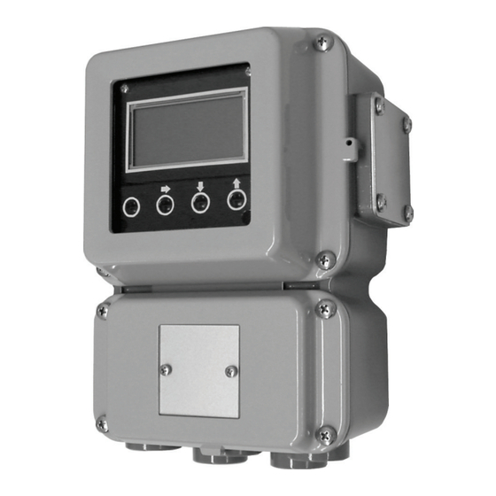
Azbil Corporation Introduction The converter consists of the components shown in the figure below. Figure 1-7 Parts of the converter Converter • Converts electromotive force by the detector to the flow rate signal. • Transmits the analog output or the digital output as the flow rate signal. -
Page 22: Approval Of This Device
Introduction Azbil Corporation Approval of this Device Overview If the basic model number is MGG14C and 1/2 NPT wiring connection is selected and style code is selected as “N”, this device functions as an FM, non-incentive- approved model. In this case, the installation standards described in this section must be followed. -
Page 23: Figure 1-8 System Configuration
Azbil Corporation Introduction Figure 1-8 System configuration Model MGG10C/14C - MagneW Converter 1-11 FLEX+/PLUS+... - Page 24 MEMO...
-
Page 25: Chapter 2: Installation
Chapter 2: Installation This chapter describes the installation and wiring procedures for the flowmeter. WARNING ELECTRIC SHOCK HAZARD! DO NOT perform wiring work while the power is ON! Site selection When selecting an installation site for the flowmeter, observe the following safety measures: CAUTION Install the flowmeter in a location with an ambient temperature of -25 °C to... -
Page 26: Unpacking And Storage
• Test report If you have questions regarding the technical specifications of the flowmeter, contact your nearest Azbil Corporation office or Azbil Corporation representative. When making an inquiry, make sure to provide the model number and product number of your flowmeter. -
Page 27: Installation Options
Azbil Corporation Installation Installation options There are three ways to install the flowmeter. Integral systems are pre-assembled with the converter attached to the detector; remote systems allow you to install the converter in a remote location - wall mounted or mounted directly to a two inch (50.8 mm) pipe. -
Page 28: Changing The Orientation Of The Converter
Installation Azbil Corporation Figure 2-3 Pipe mounted remote installation Changing the orientation of the converter The model selected when the flowmeter is purchased determines the orientation of the display. It is possible, however, to change the horizontal or vertical orientation of the converter. -
Page 29: Wiring
CAUTION Turn off the power supply before connecting the cables to the converter. The converter can be damaged. This type of damage is not covered by Azbil Corporation’s warranty. CAUTION Be sure to plug all unused conduit connections with a water tight plug. -
Page 30: Integral Wiring - 1 (1-Contact Input And 1- Contact Output)
Installation Azbil Corporation Integral wiring - 1 (1-contact input and 1- contact output) To wire a remote system, the following cables are required: • Analog output cable see page 2-16 • Pulse output cable see page 2-17 • Contact input/output cable... -
Page 31: Integral Wiring - 2 (2-Contact Input)
Azbil Corporation Installation Integral wiring - 2 (2-contact input) To wire a remote system, the following cables are required: • Analog output cable see page 2-16 • Pulse output cable see page 2-17 • Contact input/output cable see page 2-17 The following pages provide information on selecting the correct cables and wiring the system. -
Page 32: Integral Wiring - 3 (2-Contact Output)
Installation Azbil Corporation Integral wiring - 3 (2-contact output) To wire a remote system, the following cables are required: • Analog output cable see page 2-16 • Pulse output cable see page 2-17 • Contact input/output cable see page 2-17 The following pages provide information on selecting the correct cables and wiring the system. -
Page 33: Remote Wiring - 1 (1-Contact Input And 1- Contact Output)
Azbil Corporation Installation Remote wiring - 1 (1-contact input and 1- contact output) To wire a remote system, the following cables are required: • Signal cable see page 2-12 • Excitation cable see page 2-12 • Analog output cable see page 2-16 •... -
Page 34: Remote Wiring - 2 (2-Contact Input)
Installation Azbil Corporation Remote wiring - 2 (2-contact input) To wire a remote system, the following cables are required: • Signal cable see page 2-12 • Excitation cable see page 2-12 • Analog output cable see page 2-16 • Pulse output cable see page 2-17 •... -
Page 35: Remote Wiring - 3 (2-Contact Output)
Azbil Corporation Installation Remote wiring - 3 (2-contact output) To wire a remote system, the following cables are required: • Signal cable see page 2-12 • Excitation cable see page 2-12 • Analog output cable see page 2-16 • Pulse output cable see page 2-17 •... -
Page 36: Grounding
(Model MGA12W). The signal cable connects the output signal of the detector to the converter and the excitation cable feeds the excitation current to the detector. You can obtain these cables from Azbil Corporation or purchase commercially available cables. Integral flowmeters already contain the converter to detector connections. -
Page 37: Figure 2-11 Signal Cable Dimensions
Azbil Corporation Installation Detector side Converter side 90 (3.54) mm (inches) 65 (2.56) 60 (2.36) 60 (2.36) To M4 To M4 Screw Screw 60 (2.36) 60 (2.36) 90 (3.54) To M4 Screw 60 (2.36) 65 (2.56) Model A To M4 Screw 40 (1.57) -
Page 38: Signal And Excitation Cable Wiring
Installation Azbil Corporation Signal and excitation cable wiring The following figure shows the proper terminal connections for the signal and excitation cables for both model MGA12W cables and commercial cable. Dedicated cable model MGA12W Signal cable model MGA12W Converter Detector... -
Page 39: Wiring Cable
Azbil Corporation Installation Wiring cable Selecting the cable The recommended wiring cable is a 600V vinyl sheath electrical wire CVV (JIS C 3401) with a conductor section of 2 mm (0.0031 inch ), or a twisted cable with an equivalent or higher capacity. -
Page 40: Wiring
Installation Azbil Corporation Wiring Analog output wiring The current output wiring method depends on HART or SFC communication. An external power supply is required to communicate with the SFC. (Change dip switch settings only after turing power supply OFF.) With HART communications(internal power supply) -
Page 41: Figure 2-16 Wiring Diagram For Pulse Output
Azbil Corporation Installation Pulse output wiring The pulse output is an open collector output. Pay close attention to voltage and polarity when wiring. S6 switch Protective diode 200mA max. Load Avoid this polarity External power supply 30V max. Figure 2-16 Wiring diagram for pulse output ~ Note Check and confirm that the polarity of the wiring is correct. -
Page 42: Figure 2-18 Wiring Diagram For Contact Input
Installation Azbil Corporation Contact input wiring Either a semi conductive contact or a no-voltage contact can be used as the contact input. The contact input terminals are not available when a 2-contact output model has been selected. STATUS IN STATUS IN Required speci cations for the semi - conductive contact. -
Page 43: Setting Write Protection
Azbil Corporation Installation Setting write protection Write protection settings allow you to control the level at which data confirmation and manipulation are possible. The system has four modes: Basic setup mode - used to run the flowmeter on a day-to-day basis. -
Page 44: Figure 2-20 Switch Locations On Main Card
Installation Azbil Corporation To set the write protection level: 1. Remove the four screws holding the display cover to the main body of the converter and remove the cover. 2. Locate the write protection switch. Empty detection function switch Write... -
Page 45: Setting The Communication Via The Hart
Azbil Corporation Installation Setting the communication via the HART To check the communication switch position on the main card: 1. Remove the four screws holding the display cover to the main body of the converter and remove the cover. 2. Locate the communication switch... -
Page 46: Setting The Empty Detection Function
Installation Azbil Corporation Setting the empty detection function This function fixes the analog output and latches the display to zero when the detector is empty. To set the empty detection function: 1. Remove the four screws holding the display cover to the main body of the converter and remove the cover. -
Page 47: Setting The Communication Via The Sfc
Azbil Corporation Installation Setting the communication via the SFC To check the communication switch position on the main card: 1. Remove the four screws holding the display cover to the main body of the converter and remove the cover. 2. Locate the communication switch... -
Page 48: Connecting Power
Installation Azbil Corporation Connecting power WARNING ELECTRIC SHOCK HAZARD! DO NOT perform wiring work while the power is ON! Commercial power (AC100~120, 200~240V, 50-60Hz) or a 24 VDC ± 10% power supply is required for this system. The power supply specification is shown on the name plate of your converter. -
Page 49: Chapter 3: Operation
Chapter 3: Operation This chapter describes the procedure for starting and shutting down the flowmeter and using the display panel and the infrared touch sensor keys. Start-up To start operation of the flowmeter: 1. Confirm that the detector is correctly installed on the pipe. 2. -
Page 50: Figure 3-2 Display Panel
Operation Azbil Corporation Using the display panel The display panel is shown below, followed by a description of each feature. The infrared touch sensor keys are described in the next section. Main display Totalized value display FLEX TOTAL Percent flow rate display... -
Page 51: Figure 3-3 Touch Sensor Keys
Azbil Corporation Operation Using the infrared touch sensor keys The infrared touch sensor keys allow you to make selections by simply touching the display panel. MagneW3000 FLEX TOTAL RATE 0 . 0 0 m 0 0 0 0 1 2 3 4 5 6... -
Page 52: Table 3-1 Touch Sensor Key Functions
Operation Azbil Corporation The following table is a summary of the functions of each of the keys. Table 3-1 Touch Sensor key Functions Function Touching and holding this key for more than three seconds MODE key opens Basic setup MODE. -
Page 53: Table 3-2 Default Settings
Azbil Corporation Operation Table 3-1 Touch Sensor key Functions Function When the cursor is on the Mode Indicator as shown below, touching the UP key displays the next screen. When the cursor is located at a number, touching the UP key increments the number. - Page 54 MEMO...
-
Page 55: Using The Display Panel
Chapter 4: Using the display panel This chapter describes the four modes of operation and how to use each one. A flow chart of the functions for each mode is also included. About modes The MagneW Flowmeter has five modes of operation: FLEX+/PLUS+ •... -
Page 56: Table 4-1 Mode Functions
Using the display panel Azbil Corporation The following table describes the functions available in each mode. Table 4-1 Mode functions Mode Description This is the normal operational mode and indicates the measuring status. Each time the MEASURING MODE is selected, data is written into memory. - Page 57 Azbil Corporation Using the display panel Table 4-1 Mode functions Mode Description This mode is used to apply some specific noise immunity functions. This mode includes: Damping ADVANCED MODE Manual zero Mode indicator: Averaging Auto spike Cut Coefficient Drop out...
-
Page 58: Measuring Mode
Using the display panel Azbil Corporation MEASURING MODE This is the normal operational mode. In this mode, the screen indicates the measuring status. What is displayed on screen depends upon the setting selections made in the other modes. This mode performs one other important function. Entering this mode causes the system to save settings entered in other modes. -
Page 59: Lcd Display Flow
Azbil Corporation Using the display panel LCD display flow The following screens appear in this order. than 3 seconds. Move the cursor under YES by using key and press key. (to be continued) Model MGG10C/14C - MagneW Converter FLEX+/PLUS+... - Page 60 Using the display panel Azbil Corporation # ENGINEERING MODE 2 seconds later # FUNC SET FOAXX (*2) (*3) (*4) 1.4147 m/s 1.4147 m/s 1.4147 m/s SPN1 10.000 m3/h SPAN 10.000 m3/h SPN+ 10.000 m3/h Advanced mode 2.8294 m/s 2.8294 m/s SPN2 20.000 m3/h...
- Page 61 Azbil Corporation Using the display panel # FUNC SET FOAXX Single range Dual range (*10) (*8)(*10) # PLS 27.778 Hz # PLS 27.778 Hz SCL 100.00 cm3/P SCL 100.00 cm3/P (*8)(*10) (*10) # PLS 27.778 % # PLS1 27.778 % WID NUM 010.00ms...
- Page 62 Using the display panel Azbil Corporation > MAINTENANCE MODE > OUTPUT CHECK > CALIBRATION > SHIPPING INFO > MODE RETURN BASIC SET UP > OUTPUT CHECK 2 seconds later > OUTPUT CHECK I.OUT 100.0% (*14) > OUTPUT CHECK > OUTPUT CHECK P.OUT1...
- Page 63 Azbil Corporation Using the display panel > CALIBRATION 5 seconds later > CAL EXS CURRENT 160.000mA > CAL I.OUT OFF 4.000mA > CAL I.OUT OFF > CAL GAIN 50Hz HIGH 20.000mA READY > CAL GAIN 50Hz ZERO READY > CAL GAIN1 50Hz 02.50m/s READY...
- Page 64 Using the display panel Azbil Corporation & ADVANCED & DECIMAL PLACE MODE 2 seconds later (*16) (*17) & DAMPING & DECIMAL PLACE1 003.0S (*17) & MANUAL ZERO & DECIMAL PLACE2 READY & AVERAGING & EX FREQUENCY 12.5Hz & AUTO SPIKE CUT AUTO &...
-
Page 65: Entering Basic Setup Mode
Azbil Corporation Using the display panel Entering BASIC SETUP MODE The following screens appear in this order in BASIC SETUP MODE. Screen Step Procedure (English) (Japanese) Left display is an example of MEASURING MODE. Touch MODE key and hold 10.0 m3/h for three seconds. -
Page 66: Setting The Tag No
Using the display panel Azbil Corporation Setting the TAG NO. This function sets the TAG NO. of the flowmeter. Default setting XXXXXXXX Setting range 8 characters max. Alphanumeric characters, -, @, and space can be set. Screen Step Procedure (English) -
Page 67: Damping Time Constant
Azbil Corporation Using the display panel Damping time constant The damping time constant removes minute fluctuations when transmitting the measured flow rate to the control equipment. Check the amplitude of fluctuation in flow output and set the damping time constant to an appropriate value. The new value... -
Page 68: Auto Zero
Using the display panel Azbil Corporation Auto zero This function adjusts the flowmeter so that the measured flow rate is zero when the fluid is in static condition inside the detector. CAUTION Before operating the flowmeter for the first time, be sure to carry out auto zero. - Page 69 Azbil Corporation Using the display panel Screen Step Procedure (English) (Japanese) Touch the key until the cursor is back at the mode indicator. Touch the MODE key and hold AUTO ZERO READY for three seconds to return to MEASUREMENT MODE to save the zero setting.
-
Page 70: Flow Counter - Reset Value
Using the display panel Azbil Corporation Flow counter - Reset value This function sets the totalization starting value of the built-in flow counter Screen Step Procedure (English) (Japanese) To change this function, the DISPLAY SELECT must be set to TOTAL (see page 4-22). -
Page 71: Flow Counter - Resetting
Azbil Corporation Using the display panel Flow counter - Resetting This function resets the current totalized value and saves it to memory. (The default value for the counter is 000000000 at power-up.) Screen Step Procedure (English) (Japanese) Enter BASIC SETUP MODE (see page 4-11). -
Page 72: Detector Data
Using the display panel Azbil Corporation Detector data This function is used to select the constant, model and diameter of the detector being used with this converter. In this screen, three values can be changed: the detector constant (EX), detector type (MGG, KID, NNK, NNM) and the detector diameter... - Page 73 For MGG and KID type detectors, set the detector factor (EX) as the value stamped on the name plate. For NNM and NNK if you need to replace a converter with a new one, contact an Azbil Corp. representative. Model MGG10C/14C - MagneW...
-
Page 74: Setting The Number Of Dummy Detectors
Using the display panel Azbil Corporation Setting the Number of Dummy Detectors This is used to set number of dummy detectors installed with the NNK detector (selected in the detector data setting). This screen appears only for open channel type electromagnetic flowmeter NNK. -
Page 75: Flow Rate Range
Azbil Corporation Using the display panel Flow rate range This function is used to set the flow rate range (the value when the analog output reaches 100%). In this screen, three values can be changed: flow rate value, flow rate unit, and time unit. -
Page 76: Flow Rate Indication
Using the display panel Azbil Corporation Flow rate indication This function selects the flow rate indication displayed on screen. The data can be displayed as a percent (%), the actual flow rate (RATE) or the totalized value (TOTAL) Default setting As specified when ordered. -
Page 77: Entering Engineering / Advanced / Maintenance Mode
Azbil Corporation Using the display panel Entering ENGINEERING / ADVANCED / MAINTENANCE MODE This is to describe how to enter ENGINEERING, ADVANCED and MAINTENANCE MODE. ~ CAUTION Check the write protection level to enter each mode (See page 2-19). Entering ENGINEERING MODE... -
Page 78: Entering Maintenance Mode
Using the display panel Azbil Corporation Screen Step Procedure (English) (Japanese) Touch the key to select. The ADVANCED MODE screen ADVANCED MODE appears. Two seconds later, DAMPING DAMPING screen appears. 003.0S 003.0S Entering MAINTENANCE MODE Screen Step Procedure (English) (Japanese) Enter BASIC SETUP MODE (see page 4-11). -
Page 79: Selecting Functions
Azbil Corporation Using the display panel Selecting functions Introduction Sets the electromagnetic flowmeter functions: range, counter, contact input, and contact output. There will be restrictions on the functions that can be set depending on your model’s specifications. Note that the setting range will be limited depending on the selection of contact input/output. - Page 80 Using the display panel Azbil Corporation Screen Step Procedure (English) (Japanese) When completing the setting of the respective functions, touch key to move the cursor to the “#”. 4-26 Model MGG10C/14C - MagneW Converter FLEX+/PLUS+...
-
Page 81: Relations For Setting Function Fxxxx
Azbil Corporation Using the display panel Relations for setting function FXXXX Introduction The range, built-in counter, contact input, and contact output functions can be set using the combinations shown in the table below. For example, when “Single range” and “Addition with preset” are selected, there are three contact input choices (X, 1, and 2) and three contact output choices. - Page 82 Using the display panel Azbil Corporation Built-in counter Range function Contact input function Contact output function function 4: Normal/reverse A: Addition 3: External range X: Not activated external switching switching 1: Alarm output 2: Range switching output range 4: Self-check result output...
- Page 83 Azbil Corporation Using the display panel 2- contact outputs Built-in counter Contact input Range function Contact output function function function 0: Single range A: Addition X: Not activated X: Not activated E: High 1 and High 2 alarm or Low 1...
-
Page 84: Range Functions
Using the display panel Azbil Corporation Range functions Single range Measures a single range in the normal direction. The output for a reverse flow will be as follows Analog output: Possible to approx. -20% (0.8 mA). With communication, to approx. -5% (3.2 mA). -
Page 85: Normal Direction Automatic Dual Range
Azbil Corporation Using the display panel Normal direction automatic dual range This function has two ranges: wide and narrow. When the narrow range measurement exceeds 100%, the unit automatically changes to the wide range. This function should be used in combination with the wide/narrow range distinction output contact. -
Page 86: Normal Direction, External Switching Dual Range
Using the display panel Azbil Corporation Normal direction, external switching dual range The range is switched via an external switching command to the contact input. Also, the wide/narrow range distinction contact output (status signal) can be sent out using the same timing. -
Page 87: Normal/Reverse Automatic Switching Range
Azbil Corporation Using the display panel Normal/reverse automatic switching range Automatically switches the range when the fluid flow direction reverses. Hysteresis setting is available when normal/reverse switching is selected. Analog output Normal direction: 4 to 20 mA DC Reverse direction: 4 to 20 mA DC When there is a pulse output There is no distinction in output between the normal and reverse directions. - Page 88 Using the display panel Azbil Corporation Normal / Reverse external switching range Switches between the normal and reverse ranges by inputting a switching command contact from the host system or controller. It is also possible to output the normal/reverse range distinctive contact output (status signal) using the same timing.
-
Page 89: [Built-In Counter Function]
Azbil Corporation Using the display panel [Built-in counter function] A: Addition counter In the normal/reverse range, addition is performed in the normal and reverse directions, respectively. B: Addition counter with preset The preset value ranges from 0000000000 - 9999999999. In the normal/reverse range, addition is made in the normal and reverse directions, respectively. -
Page 90: [Contact Input Function]
Using the display panel Azbil Corporation [Contact input function] This function can be set when either 1- or 2-contact input has been selected in the additional specifications. X: Not activated 1: External 0% lock input Use to completely halt the flow rate signal (display, analog output, or pulse output) at 0%. -
Page 91: [Contact Output Function]
Azbil Corporation Using the display panel [Contact output function] This function can be set when 1- or 2-contact output has been selected in the additional specifications. X: Not activated 1: Alarm contact output An alarm is output when any of the following items becomes abnormal. - Page 92 Using the display panel Azbil Corporation k Empty detection function When the detector becomes empty, the respective output signals will be as follows. Status When the detector is empty Output signal Analog output 4-20 mA DC 4 mA DC Pulse output Contact output Abnormal status (Open/closed can be freely selected.)
-
Page 93: Figure 4-4 2-Stage Flow Rate Alarm Output
Azbil Corporation Using the display panel The high/low limit alarm can be set to ST.OUT1 and the range switching output to ST.OUT2. B: Range switching output and counter preset status output (2-contact output) The range switching output can be set to ST.OUT1 and the preset status output to ST.OUT2. -
Page 94: Flow Rate Range
Using the display panel Azbil Corporation Flow rate range This function is used to set the flow rate range (the value when the analog output reaches 100%). In this screen, three values can be changed: flow rate value, flow rate unit, and time unit. - Page 95 Azbil Corporation Using the display panel Screen Step Procedure (English) (Japanese) Touch the key until the cursor 2.8294 m/s 2.8294 m/s is back at the mode indicator. SPAN 333.33 l/min SPAN 333.33 l/min Model MGG10C/14C - MagneW Converter 4-41 FLEX+/PLUS+...
-
Page 96: Setting Hysteresis
Using the display panel Azbil Corporation Setting hysteresis This is used to set the hysteresis as a range function to be used at range switching. Use for normal direction automatic dual range or the normal/reverse direction automatic range. Default setting... -
Page 97: Selecting The Current Output Method For Dual Range
Azbil Corporation Using the display panel Selecting the current output method for dual range This is used as a range function with the normal direction dual range or normal/ reverse direction dual range, to select how to output the 4-20 mA analog output: with either the range switching method or the wider range method. -
Page 98: Setting / Changing The Preset Value Of The Built-In Flow Counter
Using the display panel Azbil Corporation Setting / Changing the preset value of the built-in flow counter This changes the contact output status from H to L or from L to H when the flow counter reaches a preset value. -
Page 99: Specific Gravity
Azbil Corporation Using the display panel Specific gravity This function is used to set the specific gravity when selecting a weight unit (t, kg, g, lb) in the flow rate measurement range setting. Screen Step Procedure (English) (Japanese) Enter ENGINEERING MODE (see page 4-23). -
Page 100: Pulse Weight
Using the display panel Azbil Corporation Pulse weight This function is used to set the pulse weight value and pulse weight unit. Pulse weight should be set so that pulse frequency indicated on the display is between 0.00006 and 3000Hz. -
Page 101: Setting The Pulse Width
Azbil Corporation Using the display panel Setting the pulse width This is used to set the pulse width so that the duty ratio at the upper right of the 16-digit display will not exceed 70%. When changing the pulse width with a dual range, use the wider range. - Page 102 Using the display panel Azbil Corporation Screen Step Procedure (English) (Japanese) Touch the key to move the 13.889 % PLS 13.889 % cursor to the “#”. NUM 005.00ms WID NUM 005.00ms 4-48 Model MGG10C/14C - MagneW Converter FLEX+/PLUS+...
-
Page 103: Setting High And Low Limit Alarms
Azbil Corporation Using the display panel Setting high and low limit alarms An alarm is output when the instantaneous percent flow rate exceeds the preset high and low limits. Important This function can be used when the high/low limit alarm is selected in the contact output function. -
Page 104: Setting A 2-Stage Flow Rate Alarm
Using the display panel Azbil Corporation Setting a 2-stage flow rate alarm The first alarm will be output when the instantaneous percent flow rate exceeds the preset first high or low limit. The second alarm will be output when the flow rate exceeds the second high or low limits. - Page 105 Azbil Corporation Using the display panel Screen Step Procedure (English) (Japanese) Touch the key to move the HI-ALM2 +100 % 2 + 100 % cursor to the “#”. LO-ALM2 - 20 % 2 - 20 % Model MGG10C/14C - MagneW...
-
Page 106: Selecting Fail-Safe Mode For The Analog Output
Using the display panel Azbil Corporation Selecting fail-safe mode for the analog output This function is used to determine the analog output direction when the electromagnetic flowmeter detects a critical status condition. CAUTION The fail-safe mode is very important for overall safety of the control process. -
Page 107: Selecting Fail-Safe Mode For The Pulse Output
Azbil Corporation Using the display panel Selecting fail-safe mode for the pulse output This function is used to determine the pulse output direction when the electromagnetic flowmeter detects a critical status condition. CAUTION The fail-safe mode is very important for overall safety of the control process. -
Page 108: Setting The Contact Output Status
Using the display panel Azbil Corporation Setting the contact output status This is used to set the contact output status for normal operation. Important This function is displayed when contact output has been selected. Default setting “CLOSE” Setting range “CLOSE”, “OPEN”... - Page 109 Azbil Corporation Using the display panel <For 2-contact output> Screen Step Procedure (English) (Japanese) Open the contact output status setup screen by following the ST. OUT2 MODE steps to enter the engineering NORMAL CLOSE CLOSE mode. Touch the ST. OUT1 MODE...
-
Page 110: Damping Time Constant
Using the display panel Azbil Corporation Damping time constant The damping time constant removes minute fluctuations when transmitting the measured flow rate to the control equipment. Check the amplitude of fluctuation in flow output and set the damping time constant to an appropriate value. The new value... -
Page 111: Manual Zeroing
Azbil Corporation Using the display panel Manual zeroing When piping vibration exists, process fluid slightly moves and display shows some values even though the fluid stands still. This function is used to adjust zero manually when the above phenomena occurs. -
Page 112: Setting Moving Average
Using the display panel Azbil Corporation Setting moving average This function is used to carry out the moving average processing of the measured flow rate values. In this mode, the MGG10C/14C performs the flow rate calculation every 200 ms. For example, if the moving average process time is set to 2 seconds, the moving average processing will be carried out 2 sec./200 ms=10 times. - Page 113 Azbil Corporation Using the display panel Screen Step Procedure (English) (Japanese) Touch the MODE key to return to the MEASURING MODE and save the data. Model MGG10C/14C - MagneW Converter 4-59 FLEX+/PLUS+...
-
Page 114: Auto Spike Cut Function
Using the display panel Azbil Corporation Auto spike cut function This function eliminates steep noise spikes (spike noise) in the flow rate. Noise generated when solids hit the electrode is an example of the spike noise. When the flow rate changes sharply, this function holds the outputs according to the damping time. -
Page 115: Manual Spike Cut Function
Azbil Corporation Using the display panel Manual spike cut function This function eliminates steep noise spikes (spike noise) in the flow rate. The manual spike cut function enables to set parameters, spike cut level and spike cut time to best meet the customers application. -
Page 116: Coefficient Of Compensation
Using the display panel Azbil Corporation Coefficient of compensation This function changes the Coefficient, which multiplies the output flow rate in the main display. Screen Step Procedure (English) (Japanese) Enter ADVANCED MODE (see page 4-23). Use the key to cycle COEFFICIENT &... -
Page 117: Setting The Drop-Out
Azbil Corporation Using the display panel Setting the drop-out A drop out is set to prevent incorrect integration of the flow rate. Pulse counting will pause when the flow rate is at the preset percentage of the set range. Default setting... -
Page 118: Setting The Low Flow Cut
Using the display panel Azbil Corporation Setting the low flow cut This function is used to set the low flow cutoff value. When the flow rate reaches set value, the analog output is cutoff and the display is latched to zero to avoid errors due to flow pulsation in range value closed to zero. -
Page 119: Setting Decimal Place
Azbil Corporation Using the display panel Setting decimal place This function is used to set the decimal place. The decimal place is related to the flow rate range. Default setting Same as the setting flow rate range or DECIMAL PLACE:2... -
Page 120: Change The Excitation Frequency
It should be noted that changing to a higher frequency may introduce measurement error of a few percent. Please contact Azbil Corporation for assistance before utilizing this feature. -
Page 121: Setting The Analog Output Limit
Azbil Corporation Using the display panel Setting the analog output limit This function is used to activate analog output limit. The analog output limit is determined by the values set by the HI/LO alarm function. Default setting When this function is set as ON, the analog output is output between values set as HI/ LO alarm function. -
Page 122: Change The Flow Direction
Using the display panel Azbil Corporation Change the flow direction This function is used when the detector is installed in opposite direction to the flow direction. Default setting FORWARD (the direction mark on the detector matches the direction of flow.) -
Page 123: Error History Check/Clear
Azbil Corporation Using the display panel Error history check/clear The latest eight errors can be checked. Error display If there is no error, [1 NO ERROR] is displayed. Screen Step Procedure (English) (Japanese) Enter ADVANCED MODE (see page 4-23). Use the key to cycle through the screens &... - Page 124 MEMO...
-
Page 125: Chapter 5: Maintenance And Troubleshooting
Chapter 5: Maintenance and Troubleshooting This chapter contains the maintenance and inspection procedures for the flowmeter and troubleshooting. Output signal loop check: • Analog output • Pulse output • Excitation current Simulated signal input by the calibrator Regarding the operations through SFC communicator, refer to the users manual CM2- MGG000-2001. -
Page 126: Function Check
Maintenance and Troubleshooting Azbil Corporation Function check Input and output signal loop check The analog output can be checked by using the electromagnetic flowmeter as a constant-current generator. By using this function, loop check and wiring check can be done. -
Page 127: Analog Output Check
Azbil Corporation Maintenance and Troubleshooting Analog output check The analog output can be checked by using the electromagnetic flowmeter as a constant-current generator. Default setting Existing analog output Setting range 000.0 to 115.0% Screen Step Procedure (English) (Japanese) Enter MAINTENANCE MODE (see page 4-24). -
Page 128: Pulse Output Check
Maintenance and Troubleshooting Azbil Corporation Pulse output check The pulse output can be checked by using the electromagnetic flowmeter as a pulse generator. Default setting Existing measured value Setting range 000.0 to 115.0% Screen Step Procedure (English) (Japanese) Enter MAINTENANCE MODE (see page 4-24). -
Page 129: Contact Input/Output Loop Check
Azbil Corporation Maintenance and Troubleshooting Contact input/output loop check By switching contact input terminal ON/OFF, contact input terminal status can be checked through the LCD. By switching contact output terminal ON/OFF, contact output loop can be checked. Display varies according to the selection of contact input and output. - Page 130 Maintenance and Troubleshooting Azbil Corporation Screen Step Procedure (English) (Japanese) Touch the key to move the > ST. IN CLOSE > cursor to “>”. 4 - 20 100.0 % ST. OUT OPEN Use the key to move other screen. Then the contact input and output are back to the current status (OPEN/CLOSE).
- Page 131 Azbil Corporation Maintenance and Troubleshooting <2-contact outputs> Screen Step Procedure (English) (Japanese) Enter MAINTENANCE MODE (see page 4-24). Use the key to cycle through screen until “OUTPUT CHECK” screen appears. Touch the key once to move > ST. OUT1 CLOSE >...
-
Page 132: Excitation Current Check
Maintenance and Troubleshooting Azbil Corporation Excitation current check This function is used to check the excitation current. Screen Step Procedure (English) (Japanese) Enter MAINTENANCE MODE (see page 4-24). Use the key to cycle through screen until “OUTPUT CHECK” screen appears. Touch the key once to move the cursor to “OFF”. -
Page 133: Simulated Signal By The Calibrator
Azbil Corporation Maintenance and Troubleshooting Simulated signal by the calibrator The model MGZ14 calibrator and the model F1X calibrator are available for this converter. The calibrator inputs the simulated signal to the converter. By using the calibrator, the converter function can be checked. -
Page 134: Troubleshooting
Maintenance and Troubleshooting Azbil Corporation Troubleshooting Overview Introduction If a problem occurs at Electromagnetic Flowmeter start-up and operation, the following four causes should be considered: • Misapplication of the electromagnetic flowmeter • Wrong setting or wrong operation • Electromagnetic Flowmeter malfunction •... -
Page 135: Errors At Startup
When a problem occurs at start-up, perform the procedures listed in the following table. If the problem persists, the flowmeter may be damaged and you should contact technical support. (For technical support, contact an Azbil Corp. sales representative in your area.) -
Page 136: Operation Errors
Check against the table on this page for symptoms of the error. If found, perform the steps indicated in the table. If the problem persists, the flowmeter may be damaged and you should contact technical support. (For technical support, contact an Azbil Corp. sales representative in your area.) -
Page 137: Error Messages
The following table shows the possible error codes for critical problems and what to do. If the problem persists after trying these solutions, contact technical support. (For technical support, contact an Azbil Corp. sales representative in your area.) Table 5-3 Critical Errors... -
Page 138: Error Codes For Non-Critical Problems
The following table shows the possible error codes for non-critical problems and what to do. If the problem persists after trying these solutions, contact technical support. (For technical support, contact an Azbil Corp. sales representative in your area.) Table 5-4 Non-critical... -
Page 139: Safety Precautions
Azbil Corporation Maintenance and Troubleshooting Safety precautions Introduction Correct operation is necessary for the safe and efficient use of the SFC and MagneW Carefully read the safety precautions described in this user's manual and FLEX+/PLUS+ have a thorough understanding of it before operating the product. -
Page 140: Structure And Functions Of Sfc
Maintenance and Troubleshooting Azbil Corporation Structure and functions of SFC This section presents the structure and functions of the Smart Field Communicator SFC. • Describes the key types, brief functions of keys, which are color-coded, and general rules of key operations of the SFC. - Page 142 Warranty period and warranty scope 1.1 Warranty period Azbil Corporation’s products shall be warranted for one (1) year from the date of your purchase of the said products or the delivery of the said products to a place designated by you.
- Page 143 Although acceleration of the above situation varies depending on the conditions or environment of use of the products, you are required not to use any Azbil Corporation’s products for a period exceeding ten (10) years unless otherwise stated in specifications or instruction manuals.
- Page 145 Document Number: CM2-MGG310-2001 Document Name: MagneW FLEX+/PLUS+ Electromagnetic Flowmeter Converter Model MGG10C/MGG14C User’s Manual Date: 1st edition: July. 2007 6th edition: Dec. 2018 Issued/Edited by: Azbil Corporation...
Need help?
Do you have a question about the MagneW FLEX+/PLUS+ MGG10C and is the answer not in the manual?
Questions and answers