Sign In
Upload
Download
Table of Contents
Contents
Add to my manuals
Delete from my manuals
Share
URL of this page:
HTML Link:
Bookmark this page
Add
Manual will be automatically added to "My Manuals"
Print this page
×
Bookmark added
×
Added to my manuals
Manuals
Brands
Azbil Manuals
Transmitter
PREX3000
User manual
Azbil PREX3000 User Manual
Pneumatic differential pressure transmitter
Hide thumbs
1
2
Table Of Contents
3
4
5
6
7
8
9
10
11
12
13
14
15
16
17
18
19
20
21
22
23
24
25
26
27
28
29
30
31
32
33
34
35
36
37
38
39
40
41
42
43
44
45
46
47
48
49
50
51
52
53
54
55
56
57
58
59
60
61
62
page
of
62
Go
/
62
Contents
Table of Contents
Bookmarks
Table of Contents
Table of Contents
Chapter 1. Scope
Chapter 2. General Precautions
Inspection Upon Delivery
Checking the Specifications
Transporting the Instrument
Storing the Instrument
Place of Installation
Ambient Temperature
Atmosphere
Vibration and Shock
Pressure Application
Chapter 3. Wiring
General
Specifications
Standard Specifications
Max. Working Pressure
Optional Specifications
Model Number Table
Kdp11/22
Kdp33
Kdp44
Kdp61/62
Kdp71/72
Kdp81/82
Structure
Nozzle and Flapper
Pilot Relay
Feedback Mechanism
Meter Bodies
Chapter 4. Operating Principle
Chapter 5. Installation
Place of Installation
Positioning
Bracket and Bolts
Installation of Regular-Type Meter Body
Installation of Model 61/62 and 71/72
Installation of Remote-Sealed Diaphragm Type Meter Body
Mounting Attitude
Air Supply Connection
Pressure Piping
Model 11/22/33/44/81/82
Connection of Flange Type Meter Body to Process
Elevation and Suppression
Definitions of Elevation and Suppression
Setting of Elevation / Suppression
Chapter 6. Operation Method
Differential Pressure (Flow) Transmission
Liquid Level Transmission
Chapter 7. Inspection and Maintenance
Check for Leakage from Piping
Maintaining the Meter Body and Piping
Blow Procedure
Cleaning of Meter Body
Notes for Use in Freezing Weather
Chapter 8. Service and Unit Replacement
To Replace the Pilot Relay
To Service the Pilot Relay
Chapter 9. Calibration and Adjustment
General
Calibration of Differential Pressure Transmitter
Setting of Elevation / Suppression
Setting of Elevation
Setting of Suppression
Advertisement
Quick Links
Download this manual
OM2-5220-1101
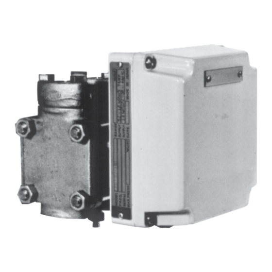
PREX3000 Pneumatic
Differential Pressure Transmitter
Model KDP
User's Manual
Table of
Contents
Previous
Page
Next
Page
1
2
3
4
5
Advertisement
Table of Contents
Need help?
Do you have a question about the PREX3000 and is the answer not in the manual?
Ask a question
Questions and answers
Related Manuals for Azbil PREX3000
Transmitter Azbil PTG71 User Manual
Smart pressure transmitter (84 pages)
Transmitter Azbil PTG60 User Manual
Smart pressure transmitter (84 pages)
Transmitter Azbil KDP User Manual
Pneumatic differential pressure transmitter (62 pages)
Transmitter Azbil MagneW Plus+ MGG14C User Manual
Electromagnetic flowmeter foundation fieldbus transmitter (110 pages)
Transmitter Azbil JTD910S User Manual
Advanced differential pressure and pressure transmitter (196 pages)
Transmitter Azbil ALTJ 9000 Series User Manual
Immersion type liquid-level transmitter (68 pages)
Transmitter Azbil KDP Series User Manual
Liquid level meter pneumatic transmitter (20 pages)
Transmitter Azbil SLX 110 User Manual
Smart displacement type level transmitter (168 pages)
Transmitter Azbil JTD720A User Manual
Smart multivariable transmitter (76 pages)
Transmitter Azbil ATT082 Brief User Manual
Temperature transmitter (32 pages)
Transmitter Azbil ATT082 Functional Safety Manual
Advanced temperature transmitter with hart protocol (56 pages)
Transmitter Azbil ATT085 User Manual
Advanced temperature transmitter with foundation fieldbus (98 pages)
Transmitter Azbil ATT085 Brief User Manual
Advanced temperature transmitter with foundation fieldbus (28 pages)
This manual is also suitable for:
Kdp
Table of Contents
Print
Rename the bookmark
Delete bookmark?
Delete from my manuals?
Login
Sign In
OR
Sign in with Facebook
Sign in with Google
Upload manual
Upload from disk
Upload from URL


Need help?
Do you have a question about the PREX3000 and is the answer not in the manual?
Questions and answers