Kollmorgen S700 Safety Manual
Hide thumbs
Also See for S700:
- Safety manual (206 pages) ,
- Instruction manual (166 pages) ,
- Manual (138 pages)
Table of Contents
Advertisement
Available languages
Available languages
Quick Links
S700
Safety Guide
Edition: September 2015
Valid for HWR 02.20
Deutsch
English
Original Language is German. All other content is translated from the genuine German content.
Keep all manuals as a product component during the life span of the product. Pass all manuals to future users and owners of the product.
Bewahren Sie alle Anleitungen während der gesamten Nutzungs-
dauer des Produkts als Produktkomponente auf. Händigen Sie alle
Anleitungen künftigen Anwendern/Besitzern des Produkts aus.
Le manuel faisant partie intégrante du produit, conservez-le
pendant toute la durée de vie du produit. Remettez le manuel au
futur utilisateur ou propriétaire du produit.
Français
Italiano
Conservare il manuale per l'intera durata del prodotto. In caso di cam-
bio di proprietà il manuale deve essere fornito al nuovo utilizzatore
quale parte integrante del prodotto.
Сохраняйте все руководства как составную часть продукта в
течение всего срока его эксплуатации. Передавайте
руководство следующему пользователю или владельцу
продукта.
Русский
Advertisement
Chapters
Table of Contents

Related Manuals for Kollmorgen S700


Summary of Contents for Kollmorgen S700
- Page 1 S700 Safety Guide Edition: September 2015 Valid for HWR 02.20 Deutsch English Français Italiano Русский Original Language is German. All other content is translated from the genuine German content. Keep all manuals as a product component during the life span of the product. Pass all manuals to future users and owners of the product.
- Page 2 Translation of the original manual, printed in the Federal Republic of Germany All rights reserved. No part of this work may be reproduced in any form (by photocopying, microfilm or any other method) or stored, processed, copied or distributed by electronic means without the written permission of Kollmorgen Europe GmbH.
-
Page 3: Table Of Contents
1.2.6 Lagerung 1.2.7 Wartung und Reinigung 1.2.8 Demontage 1.2.9 Reparatur und Entsorgung 1.3 Technische Beschreibung und Daten 1.3.1 Die digitalen Servoverstärker der Familie S700 1.3.2 Lieferumfang 1.3.3 Antriebssystem mit S701...S724 1.3.4 Antriebssystem mit S748...S772 1.3.5 Umgebungsbedingungen, Belüftung und Einbaulage 1.3.6 Empfohlene Anzugsmomente 1.3.7 Technische Daten 110 / 230 V... -
Page 4: Allgemeines
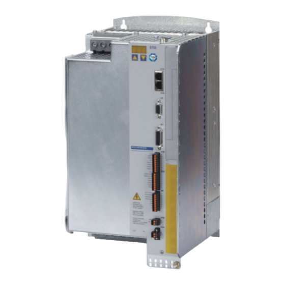
S700 Safety Guide | 1 Deutsch 1.1 Allgemeines Dieses Handbuch beschreibt die digitalen Servoverstärker S700 (Standard Version, 1,5 A bis 72 A Nennstrom). Vollständige Informationen finden Sie in der Betriebsanleitung und weiteren Kollmorgen Doku- menten: Betriebsanleitung (PDF Format): Das Handbuch enthält Hinweise zur Installation und Konfiguration des Servoverstärkers. -
Page 5: Verwendung Des Pdf Dokumentes
S700 Safety Guide | 1 Deutsch 1.1.2 Verwendung des PDF Dokumentes Das Dokument bietet verschiedene Funktionen, um die Navigation zu vereinfachen. Lesezeichen Das Inhaltsverzeichnis und der Index enthalten aktive Lesezeichen. Inhaltsverzeichnis Die Zeilen im Inhaltsverzeichnis und Index sind aktive Quer- und Index im Text verweise. -
Page 6: Verwendete Abkürzungen
S700 Safety Guide | 1 Deutsch 1.1.4 Verwendete Abkürzungen Kürzel Bedeutung (➜ # xx) Siehe Seite xx. Beispiel (➜ # 53): siehe Seite 53. AGND Analoge Masse BTB/RTO Betriebsbereit Feldbus (CANopen) Clock (Taktsignal) Serielle Schnittstelle für einen PC DGND Digitale Masse... -
Page 7: Sicherheit
Prüfen Sie die Hardware-Revisionsnummer des Produkts (siehe Typenschild). Diese Revi- sionsnummer muss mit der Hardware-Revisionsnummer auf dem Deckblatt der Betriebs- anleitung übereinstimmen. Wenn die Nummern nicht übereinstimmen, besuchen Sie das Tech-WIKI (http://www.wiki-kollmorgen.eu). Im Bereich "Download" finden Sie alle Hand- buchversionen mit Bezug zur Hardware Revisions-Nummer. Technische Daten beachten Halten Sie die technischen Daten und die Angaben zu den Anschlussbedingungen (Typen- schild und Dokumentation) ein. - Page 8 S700 Safety Guide | 1 Deutsch Automatischer Wiederanlauf Der Antrieb kann abhängig von der Parametereinstellung nach dem Einschalten der Netz- spannung, bei Spannungseinbrüchen oder Unterbrechungen automatisch anlaufen. Es besteht die Gefahr von tödlichen oder schweren Verletzungen für Personen, die in der Maschine arbeiten.
-
Page 9: Bestimmungsgemäße Verwendung
Außenleitern dürfen 1000V nicht überschreiten. Spannungsspitzen (<50μs) zwischen Außenleitern und Gehäuse dürfen 2000V nicht überschreiten. Motoren Die S700 Servoverstärker sind ausschließlich zum Antrieb von geeigneten Synchron- Servomotoren mit geschlossenem Drehmoment-, Drehzahl- und/oder Positionsregelkreis vorgesehen. Die Nennspannung der Motoren muss höher oder mindestens gleich der vom Servoverstärker gelieferten Zwischenkreisspannung sein. -
Page 10: Nicht Bestimmungsgemäße Verwendung
Bestimmungen der EG Maschinenrichtlinie entspricht nicht die Bestimmung der EMV-Richtlinie erfüllt nicht die Bestimmung der Niederspannungs-Richtlinie erfüllt Die Ansteuerung von Haltebremsen durch den S700 alleine darf nicht in Anwendungen ver- wendet werden, wo mit der Bremse die funktionale Sicherheit gewährleistet werden soll. 1.2.4 Transport Nur durch qualifiziertes Personal in der Originalverpackung des Herstellers. -
Page 11: Wartung Und Reinigung
Sie ihn in der Originalverpackung an den Hersteller. Gemäß den WEEE-2002/96/EG-Richtlinien u.ä. nimmt der Hersteller Altgeräte und Zubehör zur fachgerechten Entsorgung zurück. Die Transportkosten muss der Versender tragen. Setzen Sie sich mit Kollmorgen in Verbindung und klären Sie die logistische Abwicklung. Kollmorgen | September 2015... -
Page 12: Technische Beschreibung Und Daten
S700 Safety Guide | 1 Deutsch 1.3 Technische Beschreibung und Daten 1.3.1 Die digitalen Servoverstärker der Familie S700 Typenschlüssel Benutzen Sie den Typenschlüssel zur Produktidentifizierung, jedoch nicht für den Bestell- prozess, da nicht immer alle Merkmal-Kombinationen technisch möglich sind. Kollmorgen | September 2015... -
Page 13: Lieferumfang
Safety Erweiterung (S4) S2-2 (SIL CL2) Funktionsweise und Anschluss der Erweiterungskarten sind in der Betriebsanleitung beschrieben. 1.3.2 Lieferumfang Wenn Sie Verstärker aus der Serie S700 bei uns bestellen, erhalten Sie: S7xx diverse Gegenstecker (Steckklemmen) S700 Safety Guide gedruckt Betriebsanleitung, Online-Dokumentation und Inbetriebnahmesoftware auf CD-ROM Die SubD-Gegenstecker gehören nicht zum Lieferumfang! -
Page 14: Antriebssystem Mit S701
S700 Safety Guide | 1 Deutsch 1.3.3 Antriebssystem mit S701...S724 Kollmorgen | September 2015... -
Page 15: Antriebssystem Mit S748
S700 Safety Guide | 1 Deutsch 1.3.4 Antriebssystem mit S748...S772 Kollmorgen | September 2015... -
Page 16: Umgebungsbedingungen, Belüftung Und Einbaulage
S700 Safety Guide | 1 Deutsch 1.3.5 Umgebungsbedingungen, Belüftung und Einbaulage Lagerung, Hinweise (➜ # 10) Transport, Hinweise (➜ # 10) Leistungsversorgung S701...S724: 1x110V-10% …1x230V+10%, 50/60 Hz 3x110V-10% …3x480V+10%, 50/60 Hz S748...S772: 3x208V-10% ...3x 480V+10%, 50/60 Hz Hilfsspannungsversorgung 24 V DC (-0% +15%), S701...724: 3A, S748...772: 5A... -
Page 17: Technische Daten 110 / 230 V
S700 Safety Guide | 1 Deutsch 1.3.7 Technische Daten 110 / 230 V Nenndaten DIM S70162 S70362 S70662 S71262 S7126S S72462 S7246S +10% Nenn-Anschlussspannung (geerdetes Netz) V~ 1 x 110V ... 230V , 50/60 Hz -10% Nenn-Eingangsleistung für Dauerbetrieb @230V Nenn-DC-Bus-Zwischenkreisspannung 135...450... -
Page 18: Technische Daten 230V
S700 Safety Guide | 1 Deutsch 1.3.8 Technische Daten 230V ... 480 V S71202 S72402 Nenndaten DIM S70102 S70302 S70602 S74802 S77202 S7120S S7240S Nenn-Anschlussspannung (geerdetes +10% 3 x 208V ... 3 x 480V , 50/60 Hz -10% Netz) Nenn-Eingangsleistung für Dauerbetrieb... -
Page 19: Sicherungen
S700 Safety Guide | 1 Deutsch 1.3.9 Sicherungen Interne Absicherung Kreis Interne Sicherung 24V Versorgung Elektronik 24V Versorgung Lüfter&Bremse Bremswiderstand elektronisch Externe Absicherung Schmelzsicherung o.ä. S701/703 S706 S712 S724 S748 S772 Netzspannung F 10 A 16 A 30 A 60 A... -
Page 20: Safe Torque Off (Sto)
S700 Safety Guide | 1 Deutsch 1.3.11 Safe Torque Off (STO) Das S700 Schaltungskonzept wurde geprüft und abschließend beurteilt. Das Schal- tungskonzept zur Realisierung der Sicherheitsfunktion "Safe Torque OFF" in den Ser- voverstärkern ist demnach geeignet, die Anforderungen an SIL CL3 gem. EN 62061 und des PLe gem. - Page 21 S700 Safety Guide | 1 Deutsch 1.3.11.2 Bestimmungsgemäße Verwendung Die Funktion STO ist ausschließlich dazu bestimmt, einen Antrieb funktional sicher anzu- halten und gegen Wiederanlauf zu sichern. Um die funktionale Sicherheit zu erreichen, muss die Schaltung des Sicherheitskreises die Anforderungen der EN 60204, EN 12100, EN 62061 und EN 13849-1 erfüllen.
- Page 22 S700 Safety Guide | 1 Deutsch Anschlussbelegung S701...S724 Zum Erreichen von SIL CL3 / PLe wird der Schaltzustand der Impulssperre (Status) mit dem ASCII-Befehl OxMODE 70 auf einen der digitalen Ausgänge DIGITAL-OUT1 oder 2 (X3A/6 oder X3A/7) des S700 gelegt.
- Page 23 S700 Safety Guide | 1 Deutsch Anschlussbelegung S748...S772 Zum Erreichen von SIL CL 3 / PLe wird der Schaltzustand der Impulssperre in der Sicher- heitssteuerung periodisch getestet. Kollmorgen | September 2015...
- Page 24 S700 Safety Guide | 1 Deutsch Signaldiagramm Das Diagramm zeigt, wie die Funktion STO genutzt werden sollte, damit ein sicherer Halt des Antriebs und fehlerfreier Betrieb des Servoverstärkers gewährleistet ist. Kollmorgen | September 2015...
-
Page 25: Mechanische Installation
S700 Safety Guide | 1 Deutsch 1.4 Mechanische Installation Außenmaße der Geräte und Einbau (➜ # 196). 1.4.1 Wichtige Hinweise VORSICHT Es besteht Stromschlaggefahr durch hohe EMV-Ströme, die zu Ver- letzungen führen können, wenn der Servoverstärker (oder der Motor) nicht EMV-gerecht geerdet ist. -
Page 26: Elektrische Installation
S700 Safety Guide | 1 Deutsch 1.5 Elektrische Installation Anschluss Übersicht (➜ # 204). Anschlusspläne und Schnittstellenbeschreibungen finden Sie in der Betriebsanleitung. 1.5.1 Wichtige Hinweise WARNUNG Trennen Sie nie die elektrischen Verbindungen zum Servoverstärker, wäh- rend dieser Spannung führt. Es besteht die Gefahr von Lichtbogenbildung mit Schäden an Kontakten und erhebliche Verletzungsgefahr. -
Page 27: Anleitung Für Die Elektrische Installation
S700 Safety Guide | 1 Deutsch 1.5.2 Anleitung für die elektrische Installation Die folgenden Hinweise sollen Ihnen helfen, bei der elektrischen Installation in einer sinn- vollen Reihenfolge vorzugehen ohne etwas Wichtiges zu vergessen. Leitungswahl Wählen Sie Leitungen gemäß EN 60204 aus. -
Page 28: Inbetriebnahme
S700 Safety Guide | 1 Deutsch 1.6 Inbetriebnahme Detaillierte Informationen finden Sie in der Betriebsanleitung. 1.6.1 Wichtige Hinweise Der Hersteller der Maschine muss vor der Prüfung und Inbetriebnahme eine Risikobeurtei- lung für die Maschine erstellen und geeignete Maßnahmen ergreifen, um sicherzustellen, dass unvorhergesehene Bewegungen nicht zu Verletzungen oder Sachschäden führen. -
Page 29: Tastenbedienung / Led-Display
S700 Safety Guide | 1 Deutsch 1.6.2 Tastenbedienung / LED-Display Sie können mit den beiden Tasten folgende Funktionen ausführen: Taste Funktionen einmal drücken : ein Menüpunkt nach oben, Zahl um eins vergrößern zweimal schnell hintereinander drücken : Zahl um zehn vergrößern einmal drücken : ein Menüpunkt nach unten, Zahl um eins verkleinern... -
Page 30: Basis Test
CD-Laufwerksbuchstabe) ein. Klicken Sie OK und gehen dann wie oben beschrie- ben vor. Anschluss an serielle Schnittstelle des PC Schließen Sie die Übertragungsleitung an eine serielle Schnittstelle Ihres PC und an die seri- elle Schnittstelle (X6) des S700 an (➜ # 204). Kollmorgen | September 2015... - Page 31 S700 Safety Guide | 1 Deutsch 1.6.3.3 Minimale Verdrahtung für den Schnelltest S701...S724 ohne Last Diese Verdrahtung erfüllt keinerlei Anforderungen an die Sicherheit oder Funktionstüchtigkeit Ihrer Anwendung. Sie zeigt lediglich die für den Schnelltest erforderliche Mindestverdrahtung. Kollmorgen | September 2015...
- Page 32 S700 Safety Guide | 1 Deutsch 1.6.3.4 Minimale Verdrahtung für den Schnelltest S748...S772 ohne Last Diese Verdrahtung erfüllt keinerlei Anforderungen an die Sicherheit oder Funktionstüchtigkeit Ihrer Anwendung. Sie zeigt lediglich die für den Schnelltest erforderliche Mindestverdrahtung. Kollmorgen | September 2015...
- Page 33 1.6.3.5 Verbinden Schließen Sie die Übertragungs-Leitung an eine serielle Schnittstelle Ihres PC und an die serielle Schnittstelle (X6) des S700 an. Optional ist der Einsatz eines USB - Seriell Kon- verters möglich. Schalten Sie die 24 V-Spannungsversorgung des Servoverstärkers ein.
- Page 34 S700 Safety Guide | 1 Deutsch Wenn eine Kommunikation zustande kommt, werden die Parameter aus dem Servover- stärker ausgelesen. Danach sehen Sie den Startbildschirm. Vergewissern Sie sich, dass der Verstärker gesperrt ist: (Eingang HW-Enable Klemme X3A/1 = 0 V oder offen)! 1.6.3.6 Wichtige Bildschirmelemente...
- Page 35 S700 Safety Guide | 1 Deutsch 1.6.3.7 Setup Wizzard Der Setup-Wizard führt Sie durch die notwendigen Schritte bei der Basiskonfiguration Ihres Antriebes. Abhängig von der zu lösenden Aufgabe werden nur die Bildschirmseiten dar- gestellt, die benötigt werden. Wählen Sie für einen Schnelltest der Funktionalität den Setup-Typ "Schnelleinstellung".
- Page 36 S700 Safety Guide | 1 Deutsch 1.6.3.9 Einheiten Die Benutzer-Einheiten für alle Eingaben innerhalb der Inbetriebnahmesoftware werden hier vorgewählt. Lage, Geschwindigkeit, Beschleunigung Wählen Sie hier sinnvolle Einheiten für Ihre Anwendung bezogen auf die bewegte Last. Posi- tionsänderung pro Umdrehung Hier wird ein Bezug zwischen Umdrehung der Motorwelle und Verfahrweg der Last hergestellt.
- Page 37 S700 Safety Guide | 1 Deutsch 1.6.3.10 Motor (rotatorisch) / Feedback Feedback: Wählen Sie das im Motor verwendete Feedbacksystem. Die Resolverpolzahl ist im Setupmodus "Schnelleinstellung" auf 2 festgelegt! Falls nötig, ändern Sie die Polzahl im "Komplettes Setup" auf der Seite "Feedback".
- Page 38 S700 Safety Guide | 1 Deutsch 1.6.3.12 Parameter speichern und Neustart Sie sind dabei, die Basisinstallation zu beenden und Sie haben Parameter geändert / ein- gestellt. Abhängig davon, welche Parameter Sie geändert haben, gibt es nun zwei mögliche Reaktionen des Systems: Wichtige Konfigurations-Parameter wurden geändert...
-
Page 39: Fehlerbehebung
S700 Safety Guide | 1 Deutsch 1.7 Fehlerbehebung Abhängig von den Bedingungen in Ihrer Anlage können vielfältige Ursachen für die auftretende Störung ver- antwortlich sein. Bei Mehrachssystemen können weitere versteckte Fehlerursachen vorliegen. Detaillierte Beschreibung von Fehlerursachen und Tipps zur Behebung finden Sie im Abschnitt "Trouble-Shooting"... - Page 40 S700 Safety Guide | 1 Deutsch --- / --- Kollmorgen | September 2015...
- Page 41 2.2.7 Maintenance and Cleaning 2.2.8 Disassembling 2.2.9 Repair and Disposal 2.3 Technical description and data 2.3.1 The S700 Family of digital servo amplifiers 2.3.2 Package Supplied 2.3.3 Motion system with S701...S724 2.3.4 Motion system with S748...S772 2.3.5 Ambient Conditions, Ventilation, and Mounting Position 2.3.6 Recommended Tightening Torques...
-
Page 42: General
S700 Safety Guide | 2 English 2.1 General This manual describes the digital servo amplifiers of the S700 (standard version, 1.5 to 72 A nominal current). For full information refer to the Instructions Manual and additional Kollmorgen documents: Instructions Manual (PDF format): This manual provides instructions for installation and servo amplifier setup. -
Page 43: Using The Pdf Format
S700 Safety Guide | 2 English 2.1.2 Using the PDF Format This document includes several features for ease of navigation: Cross References Table of contents and index include active cross references. Table of contents and Lines are active cross references. Click on the line and the appro- index priate page is accessed. -
Page 44: Abbreviations Used
S700 Safety Guide | 2 English 2.1.4 Abbreviations Used Abbrev. Meaning (➜ # xx) See page xx. Example (➜ # 53): see page 53. AGND Analog ground BTB/RTO Ready to operate Fieldbus (CANopen) Clock signal Serial interface for a PC-AT... -
Page 45: Safety
Hardware Revision Number on the cover page of the manual. If the num- bers do not match up, visit the Tech-WIKI ( (http://www.wiki-kollmorgen.eu). The 'Download' section contains the various manual versions based on the hardware version number. - Page 46 Thermal sensors, motor holding brakes and feedback systems built into the connected motor must have reinforced insulation (according to IEC61800-5-1) against system components with power voltage, according to the required application test voltage. All Kollmorgen com- ponents meet these requirements.
-
Page 47: Use As Directed
2000V. Motors The S700 family of servo amplifiers is only intended to drive specific brushless syn- chronous servomotors, with closed-loop control of torque, speed and/or position. The rated voltage of the motors must be at least as high as the DC bus link voltage of the servo amplifier. -
Page 48: Prohibited Use
EMC Directive or with the Low Voltage Directive, does not comply with any national directives. The control of holding brakes by the S700 alone may not be used in applications, where func- tional safety is to be ensured with the brake. -
Page 49: Maintenance And Cleaning
S700 Safety Guide | 2 English 2.2.7 Maintenance and Cleaning The servo amplifier does not require maintenance. Opening the servo amplifier voids the war- ranty. The inside of the unit can only be cleaned by the manufacturer. To clean the device exterior: Casing: Clean with Isopropanol or similar cleaning solution. -
Page 50: Technical Description And Data
S700 Safety Guide | 2 English 2.3 Technical description and data 2.3.1 The S700 Family of digital servo amplifiers Part Number Scheme Use the part number scheme for product identification only, not for the order process, because not all combinations of features are possible, always. -
Page 51: Package Supplied
3 x 208V-10% ... 3 x 480V+ 10% (S7010-S7720, S7xx0) Overvoltage category III acc. to EN 61800-5-1. DC supply via DC bus link possible (for details, contact Kollmorgen). 2 analog setpoint inputs. Integrated CANopen (default 500 kBaud), for integration into CAN bus systems and for setting parameters for several amplifiers via the PC-interface of one amplifier. -
Page 52: Motion System With S701
S700 Safety Guide | 2 English 2.3.3 Motion system with S701...S724 Kollmorgen | September 2015... -
Page 53: Motion System With S748
S700 Safety Guide | 2 English 2.3.4 Motion system with S748...S772 Kollmorgen | September 2015... -
Page 54: Ambient Conditions, Ventilation, And Mounting Position
S700 Safety Guide | 2 English 2.3.5 Ambient Conditions, Ventilation, and Mounting Position Storage, hints (➜ # 48) Transport, hints (➜ # 48) Mains power supply S701...S724: 1x110V-10% …1x230V+10%, 50/60 Hz 3x110V-10% …3x480V+10%, 50/60 Hz S748...S772: 3x208V-10% ...3x 480V+10%, 50/60 Hz Aux. -
Page 55: Technical Data 110 / 230 V
S700 Safety Guide | 2 English 2.3.7 Technical Data 110 / 230 V Rated data DIM S70162 S70362 S70662 S71262 S7126S S72462 S7246S +10% Rated supply voltage (grounded system) 1 x 110V ... 230V , 50/60 Hz -10% Rated installed load for continuous operation... -
Page 56: Technical Data 230V
S700 Safety Guide | 2 English 2.3.8 Technical Data 230V ... 480 V S71202 S72402 Rated data DIM S70102 S70302 S70602 S74802 S77202 S7120S S7240S +10% Rated supply voltage (grounded system) 3 x 208V ... 3 x 480V , 50/60 Hz... -
Page 57: Fusing
S700 Safety Guide | 2 English 2.3.9 Fusing Internal Fusing Circuit internal fuse 24V supply electronics 24V supply motor brake Brake resistor electronic External fusing Fusible cutouts or similar S701/703 S706 S712 S724 S748 S772 AC supply F 10 A... -
Page 58: Safe Torque Off (Sto)
The STO safety implementation on the is certified. The safety circuit concept for realizing the safety function "Safe Torque Off" in the servo amplifiers S700 is suited for SIL CL3 according to IEC 62061 and PLe according to ISO 13849-1. - Page 59 S700 Safety Guide | 2 English 2.3.11.2 Use as directed The safety function STO is exclusively intended to provide functional safety, by preventing the restart of a system. To achieve this functional safety, the wiring of the safety circuits must meet the safety requirements of IEC 60204, ISO 12100, IEC 62061 and ISO 13849-1.
- Page 60 S700 Safety Guide | 2 English Pinout S701...S724 To achieve PLe / SIL CL3, the safe switching of the pulse inhibitor must be tested peri- odically by analyzing the status signal from a safety control. Therefore the status must be linked to one of the digital outputs DIGITAL-OUT1 or 2 (X3A/6 or X3A/7) with the ASCII com- mand OxMODE70.
- Page 61 S700 Safety Guide | 2 English Pinout S748...S772 To achieve PLe / SIL CL3, the safe switching of the pulse inhibitor must be tested peri- odically by analyzing the status signal from a safety control. Kollmorgen | September 2015...
- Page 62 S700 Safety Guide | 2 English Signal diagram The diagram shows how to use STO function to ensure a safe stop of the drive and error free operation of the servo amplifier. Kollmorgen | September 2015...
-
Page 63: Mechanical Installation
S700 Safety Guide | 2 English 2.4 Mechanical Installation Dimensions and mounting see (➜ # 196). 2.4.1 Important Notes CAUTION There is a danger of electrical shock by high EMC level which could res- ult in injury, if the servo amplifier (or the motor) is not properly EMC-groun- ded. -
Page 64: Electrical Installation
S700 Safety Guide | 2 English 2.5 Electrical Installation For connector overview (➜ # 204). For more interface pinout refer to the Instructions Manual. 2.5.1 Important Notes WARNING Never remove electrical connections to the servo amplifier while it is live. -
Page 65: Guide To Electrical Installation
S700 Safety Guide | 2 English 2.5.2 Guide to electrical installation The following notes should assist you to carry out the electrical installation in a sensible sequence, without overlooking anything important. Cable Select cables according to EN 60204 selection Grounding... -
Page 66: Setup
S700 Safety Guide | 2 English 2.6 Setup For step-by-step setup guidance refer to the Instructions Manual. 2.6.1 Important Notes Before testing and setup, the manufacturer of the machine must generate a risk assessment for the machine and take appropriate measures so that unforeseen movements cannot cause injury or damage to any person or property. -
Page 67: Key Operation / Led Display
S700 Safety Guide | 2 English 2.6.2 Key operation / LED display The two keys can be used to perform the following functions: Key symbol Functions press once : go up one menu item, increase number by one press twice in rapid succession : increase number by ten... -
Page 68: Initial Drive Test
S700 Safety Guide | 2 English 2.6.3 Initial Drive Test 2.6.3.1 Preparation Unpacking, Mounting and Wiring the Servo Amplifier 1. Unpack servo amplifier and accessories. 2. Observe safety instructions in the manuals. 3. Mount the servo amplifier as described in chapter (➜ # 63) 4. - Page 69 S700 Safety Guide | 2 English 2.6.3.3 Minimum Wiring for Drive Test S701...S724 without load This wiring does not fulfill any requirements to safety or functionality of your application, it just shows the required wiring for drive testing without load.
- Page 70 S700 Safety Guide | 2 English 2.6.3.4 Minimum Wiring for Drive Test S748...S772 without load This wiring does not fulfill any requirements to safety or functionality of your application, it just shows the required wiring for drive testing without load.
- Page 71 S700 Safety Guide | 2 English 2.6.3.5 Connect Connect the interface cable to a serial interface on your PC and to the serial interface X6 of the servo amplifier. USB to serial converter can be used optionally. Switch on the 24 V power supply for the servo amplifier.
- Page 72 S700 Safety Guide | 2 English If communication works, you see the start screen. Select "Setup Wizard" in the navigation frame. Make sure, that the amplifier is disabled (Input Enable con- nector X3A pin 1 must be 0 V or open)! 2.6.3.6 Important Screen Elements...
- Page 73 S700 Safety Guide | 2 English 2.6.3.7 Setup Wizzard The Setup Wizard leads you through the necessary steps for configuring your servo amp- lifier. Depending on the selected application, only the active screen pages are necessary. For a quick setup / drive test, select the setup type "Quick Motor/Drive Setup".
- Page 74 S700 Safety Guide | 2 English 2.6.3.9 Units/Mechanical The user units for all input fields in the setup software can be preselected here. Position, Velocity, Acceleration Select usable units for your application referring to the moved load. The relationship between motor shaft revolution (pole pait pitch with linear motors) and motion distance of the load is specified here.
- Page 75 S700 Safety Guide | 2 English 2.6.3.10 Motor (rotary) / Feedback Feedback: Select the feedback system used in the motor. Resolver is fixed to 2 pole in the Quick Motor/Drive Setup ! Change "pole n°" on feedback screen in Complete Setup later, if required.
- Page 76 S700 Safety Guide | 2 English 2.6.3.12 Save Parameters and Restart You are going to finish the Setup Wizard and you have changed several basic parameters. Depending on the parameters you changed, two possible reactions will occure now: Configuration parameters changed A warning appears, that you have to restart the amplifier, this is called "coldstart".
-
Page 77: Trouble Shooting
S700 Safety Guide | 2 English 2.7 Trouble shooting Depending on the conditions in your installation, there may be a wide variety of reasons for the fault. In multi-axis systems there may be further hidden causes of a fault. Detailled hints for removal of faults can be found in the online help chapter "Trouble-Shoot-... - Page 78 S700 Safety Guide | 2 English --- / --- Kollmorgen | September 2015...
- Page 79 3.2.7 Maintenance et nettoyage 3.2.8 Désinstallation 3.2.9 Réparation et mise au rebut 3.3 Déscription technique et donnée techniques 3.3.1 Les variateurs numériques de la famille S700 3.3.2 Etendue de la livraison 3.3.3 Système d'entraînement avec S701...S724 3.3.4 Système d'entraînement avec S748...S772 3.3.5 Conditions ambiantes, aération, position de montage...
-
Page 80: Généralités
S700 Safety Guide | 3 Français 3.1 Généralités Ce manuel présente la série de variateurs numériques S700 (modèle standard, de 1,5 A à 72 A courant nominal) Vous trouverez des informations complètes dans le Manuel d'Instructions et dans d'autres documents Kollmorgen: Manuel d’Instructions (format PDF):... -
Page 81: Utilisation Du Format Pdf
S700 Safety Guide | 3 Français 3.1.2 Utilisation du format PDF Ce document présente diverses fonctionnalités destinées à faciliter la navigation. Références croisées Le sommaire et l'index comportent des références croisées actives. Sommaire et index Les lignes représentent des références croisées actives. Cli- quez sur la ligne pour accéder à... -
Page 82: Abréviations
S700 Safety Guide | 3 Français 3.1.4 Abréviations Abréviation Signification (➜ # xx) Voir page xx. Exemple (➜ # 53): voir page 53. AGND Masse analogique Automate programmable industriel BTB/RTO Prêt à fonctionner Bus de terrain (CANopen) Clock (signal de synchronisation) Interface sérielle d'un PC-AT... -
Page 83: Sécurité
Vérifiez le numéro de version matérielle du produit (voir plaque signalétique). Ce numéro doit correspondre aux indications figurant sur la page de titre du présent manuel. Si les numéros ne correspondent pas, consultez notre “Tech-WIKI” (http://www.wiki-kollmorgen.eu). Dans la rubrique "Download", vous trouverez toutes les versions du manuel en rapport avec le numéro de révision du matériel. - Page 84 être pourvus d’une isolation renforcée (selon la norme EN 61800- 5-1) par rapport aux composants systèmes dotés d’une tension d’alimentation, confor- mément à la tension d’essai requise de l’application. Tous les composants de Kollmorgen satisfont à ces exigences.
-
Page 85: Utilisation Conforme
S700 Safety Guide | 3 Français 3.2.2 Utilisation conforme Les S700 sont montés en tant que composants dans des installations ou des machines électriques. Ils ne peuvent être mis qu’en service en tant que composants intégrés. Le constructeur de la machine doit faire établir une appréciation du risque pour la machine et prendre les mesures appropriées pour que des mouvements intempestifs n’entraînent... -
Page 86: Utilisation Non Conforme
à la disposition de la directive basse tension. La commande des freins de maintien par le S700 seul ne peut pas être utilisée dans le cadre d’applications où la sécurité fonctionnelle doit être assurée par le frein. -
Page 87: Maintenance Et Nettoyage
S700 Safety Guide | 3 Français 3.2.7 Maintenance et nettoyage Le variateur ne requiert aucune maintenance. Le fait d'ouvrir le variateur annule la garantie. L'intérieur de l'unité ne peut être nettoyé que par le fabricant. Pour nettoyer l'extérieur du variateur : Carter : nettoyez avec de l'isopropanol ou une solution de nettoyage similaire. -
Page 88: Déscription Technique Et Donnée Techniques
S700 Safety Guide | 3 Français 3.3 Déscription technique et donnée techniques 3.3.1 Les variateurs numériques de la famille S700 Clé de type Utilisez le code de type uniquement à des fins d'identification des produits. Ne pas utiliser le code type pour les bons de commande, comme toutes les combinaisons de caractéristiques ne sont pas techniquement possible. -
Page 89: Etendue De La Livraison
Carte d’expansion Safety (S4) S2-2 (SIL CL2) Opération et la connexion des cartes d'extension sont décrits dans le Manuel d’Instructions. 3.3.2 Etendue de la livraison Si vous nous commandez des variateurs de la série S700, vous recavrez : S7xx Contre-fiches diverses S700 Safety Guide imprimé... -
Page 90: Système D'entraînement Avec S701
S700 Safety Guide | 3 Français 3.3.3 Système d'entraînement avec S701...S724 Kollmorgen | September 2015... -
Page 91: Système D'entraînement Avec S748
S700 Safety Guide | 3 Français 3.3.4 Système d'entraînement avec S748...S772 Kollmorgen | September 2015... -
Page 92: Conditions Ambiantes, Aération, Position De Montage
S700 Safety Guide | 3 Français 3.3.5 Conditions ambiantes, aération, position de montage Stockage (➜ # 86) Transport (➜ # 86) Alimentation en puissance S701...S724: 1x110V-10% …1x230V+10%, 50/60 Hz 3x110V-10% …3x480V+10%, 50/60 Hz S748...S772: 3x208V-10% ...3x 480V+10%, 50/60 Hz Alimentation en auxiliaire 24 V DC (-0% +15%), S701...724: 3A, S748...772: 5A,... -
Page 93: Donnée Techniques 110 / 230 V
S700 Safety Guide | 3 Français 3.3.7 Donnée techniques 110 / 230 V Données nominales DIM S70162 S70362 S70662 S71262 S7126S S72462 S7246S Tension de raccordement nominale (réseau +10% 1 x 110V ... 230V , 50/60 Hz mis à la terre) -
Page 94: Donnée Techniques 230V
S700 Safety Guide | 3 Français 3.3.8 Donnée techniques 230V ... 480 V S71202 S72402 Données nominales DIM S70102 S70302 S70602 S74802 S77202 S7120S S7240S Tension de raccordement nominale (réseau +10% 3 x 208V ... 3 x 480V , 50/60 Hz -10% mis à... -
Page 95: Protection
"Memory Card". La carte mémoire ne peut être enfichée ou retirée du variateur S700 que s’il est déconnecté. En cas d’utilisation d’un codeur absolu, un trajet de référence doit être effectué après la lec- ture des paramètres dans un nouvel appareil. -
Page 96: Fonction De Suppression Sûre Du Couple (Sto)
3.3.11 Fonction de suppression sûre du couple (STO) Le concept de sûreté STO est certifié. Le concept de circuit de sûreté pour réaliser la fonction de sûreté STO "Safe Torque Off" dans l'S700 approprié à SIL3 selon EN 61508-2 et PLe selon ISO 13849-1. - Page 97 S700 Safety Guide | 3 Français 3.3.11.2 Utilisation recommandée La fonction STO sert uniquement à arrêter un entraînement en toute sécurité fonctionnelle. Pour ce faire, le câblage des circuits de sécurité doit respecter les exigences de sécurité des normes EN 60204, EN 12100, EN 62061 et EN 13849.
- Page 98 Brochage S701...S724 Pour atteindre SIL CL3 / PLe, l’état de commutation du blocage d’impulsions (état) est défini sur l’une des sorties numériques DIGITAL-OUT1 ou 2 (X3A/6 ou X3A/7) du variateur S700à l’aide de la commande ASCII OxMODE 70. Kollmorgen | September 2015...
- Page 99 S700 Safety Guide | 3 Français Brochage S748...S772 Pour atteindre SIL CL 3 / Ple, l'état de commutation du blocage d'impulsions dans la com- mande de sécurité est testé périodiquement. Kollmorgen | September 2015...
- Page 100 S700 Safety Guide | 3 Français Schéma de la fonction Le schéma montre comment la fonction STO doit être utilisée afin de garantir un arrêt en toute sécurité de l’entraînement et un fonctionnement sans problème du variateur. Kollmorgen | September 2015...
-
Page 101: Installation Mécanique
S700 Safety Guide | 3 Français 3.4 Installation mécanique Aperçu dimensions voir et la position de montage dans l'armoire voir (➜ # 196). 3.4.1 Remarques Importantes AVERTISSEMENT Il existe un risque de choc électrique avec des niveaux CEM élevés pou- vant entraîner des blessures si une mise à... -
Page 102: Installation Électrique
S700 Safety Guide | 3 Français 3.5 Installation électrique Panoramica spina (➜ # 204). Pour schémas de câblage et brochage voir Manuel d'Ins- tructions. 3.5.1 Remarques Importantes AVERTISSEMENT Ne débranchez jamais les connexions électriques du variateur pendant qu’il est sous tension. Il existe un risque de formation d’arc électrique pou- vant entraîner une détérioration des contacts et des blessures graves. -
Page 103: Guide D'installation Électrique
S700 Safety Guide | 3 Français 3.5.2 Guide d’installation électrique Les indications suivantes ont pour but de vous aider à effectuer à l'installation dans une suite logique, sans omettre quelque chose d'important. Sélection de Sélectionnez les câbles selon la norme EN 60204. -
Page 104: Mise En Service
S700 Safety Guide | 3 Français 3.6 Mise en service Pour plus d'informations, reportez-vous aux Manuel d'Instructions. 3.6.1 Remarques Importantes Avant le test et la configuration, le fabricant de la machine doit effectuer une appréciation du risque pour celle-ci et prendre les mesures appropriées afin d'éviter tout dommage corporel ou matériel provoqué... -
Page 105: Utilisation Des Touches / Affichage Del
S700 Safety Guide | 3 Français 3.6.2 Utilisation des touches / Affichage DEL Les deux touches vous permettent d'exécuter les fonctions suivantes : Symbole Fonction appuyer une fois: un point de menu vers le haut, incrémentation d'1 du chiffre appuyer rapidement deux fois successivement: incrémentation de 10 du chiffre appuyer une fois: un point de menu vers le bas, décrémentation d'1 du chiffre... -
Page 106: Test Rapides
S700 Safety Guide | 3 Français 3.6.3 Test rapides 3.6.3.1 Préparation Déballer et installer et câbler du variateur 1. Retirer le variateur et les accessoires de l’emballage 2. Respecter les avertissements des manuels. 3. Monter le variateur comme décrit dans chapitre (➜ # 101). - Page 107 S700 Safety Guide | 3 Français 3.6.3.3 Câblage minimal pour le test rapide S701...S724 sans charge Ce câblage ne remplit pas d’exigences en matière de sécurité ou efficacité du fonc- tionnement de votre application. Elle ne montre que le câblage minimal nécessaire pour le test rapides.
- Page 108 S700 Safety Guide | 3 Français 3.6.3.4 Câblage minimal pour le test rapide S748...S772 sans charge Ce câblage ne remplit pas d’exigences en matière de sécurité ou efficacité du fonc- tionnement de votre application. Elle ne montre que le câblage minimal nécessaire pour le test rapides.
- Page 109 S700 Safety Guide | 3 Français 3.6.3.5 Connexion Raccordez le câble de transmission à une interface série de votre PC et à l’interface série X6 du variateur. En option, il est possible d’utiliser un convertisseur série/USB. Branchez l’alimentation 24 V de votre variateur.
- Page 110 S700 Safety Guide | 3 Français Une fois la communication établie, un écran d’accueil s’affiche. Sélectionnez “Setup Wizard” dans la fenêtre de navigation. Assurez-vous que le variateur est verrouillé (borne d’entrée HW-Enable X3A /1 à 0 V ou ouverte) ! 3.6.3.6 Eléments importants de l’écran...
- Page 111 S700 Safety Guide | 3 Français 3.6.3.7 Setup Wizzard L’assistant de configuration vous guide tout au long de la procédure de configuration de base de votre entraînement. Selon la tâche à effectuer, seuls les écrans nécessaires sont affi- chés. Pour un test rapide de fonctionnement, sélectionnez le type de configuration rapide.
- Page 112 S700 Safety Guide | 3 Français 3.6.3.9 Unités Les unités utilisateur pour toutes les saisies dans le logiciel de mise en service sont pré- sélectionnées dans cet écran. Position, Velocity, Acceleration Sélectionnez des unités pertinentes pour votre application en fonction de la charge déplacée.
- Page 113 S700 Safety Guide | 3 Français 3.6.3.10 Moteur (rotatif) et feedback Feedback: Sélectionnez le système de rétroaction (feedback) utilisé dans le moteur Le nombre de pôles du résolveur est défini sur 2 dans le mode de configuration Quick Setup! Le cas échéant, modifiez le nombre de pôles dans la fenêtre Feedback de "Complete Setup".
- Page 114 S700 Safety Guide | 3 Français 3.6.3.12 Enregistrement des paramètres et redémarraget Vous êtes sur le point de quitter l’assistant de configuration et vous avez modifié et défini les paramètres requis. Selon les paramètres modifiés, deux réactions du système sont pos- sibles : Des paramètres de configuration importants ont été...
-
Page 115: Elimination Des Défauts
S700 Safety Guide | 3 Français 3.7 Elimination des défauts En fonction des spécifications de votre installation, différentes causes peuvent être à la source du défaut apparu. En présence de systèmes multiaxes, d'autres causes d'erreur cachées peuvent apparaître. Vous trouverez des informations relatives à la réparation des anomalies dans le paragraphe « ... - Page 116 S700 Safety Guide | 3 Français --- / --- Kollmorgen | September 2015...
- Page 117 S700 Safety Guide | 4 Italiano 4 Italiano 4.1 Indicazioni generali 4.1.1 Note per la versione stampata (versione cartacea) 4.1.2 Uso del formato PDF 4.1.3 Simboli usati 4.1.4 Abbreviazioni utilizzate 4.2 Sicurezza 4.2.1 Attenersi a queste indicazioni! 4.2.2 Uso conforme 4.2.3 Uso vietato...
-
Page 118: Indicazioni Generali
S700 Safety Guide | 4 Italiano 4.1 Indicazioni generali Questo manuale descrive i servoamplificatori digitali della serie S700 (versione standard, corrente nominale 1,5 A..72 A). Per informazioni più dettagliate si rimanda al Manuale d'Instruzione e agli altri documenti Kollmorgen: Manuale d'Instruzione (PDF): Questo manuale fornisce le istruzioni per l'installazione e la configurazione dell'unità.. -
Page 119: Uso Del Formato Pdf
S700 Safety Guide | 4 Italiano 4.1.2 Uso del formato PDF Questo documento comprende svariate caratteristiche per facilitare la navigazione Riferimenti incrociati L'indice e l'indice analitico contengono riferimenti incrociati attivi. Indice e indice analitico Le linee rappresentano riferimenti incrociati attivi. Fare clic sulle linee per accedere alla pagina richiesta. -
Page 120: Abbreviazioni Utilizzate
S700 Safety Guide | 4 Italiano 4.1.4 Abbreviazioni utilizzate Abbreviazione Significato (➜ # xx) Vedere a pagina xx. Esempio (➜ # 53): vedere a pagina 53. AGND Massa analogica BTB/RTO Operativo Bus di campo CANopen Clock (segnale temporizzato) Interfaccia seriale di un PC... -
Page 121: Sicurezza
L’errata manipolazione del servoamplificatore può comportare danni a persone o a cose. L'operatore è quindi tenuto ad assicurarsi che tutto il personale addetto a lavori sugli S700 abbia letto e compreso il manuale e che le indicazioni di sicurezza riportate nel manuale siano rispettate. - Page 122 (secondo EN 61800-5-1) nei confronti dei componenti del sistema con tensione di alimentazione, in base alla tensione di prova richiesta dall’applicazione. Tutti i componenti Kollmorgen rispondono a questi requisiti. Non modificare gli apparecchi Non è...
-
Page 123: Uso Conforme
(< 50μs) tra conduttori esterni ed alloggiamento non possono superare i 2000 V. Motori I servoamplificatori della famiglia S700 sono destinati esclusivamente all'azionamento di servomotori sincroni brushless adatti con regolazione di coppia, velocità e/o posizione. La tensione nominale dei motori deve essere superiore o almeno uguale alla tensione di circuito intermedio fornita dal servoamplificatore. -
Page 124: Uso Vietato
Direttiva sulla compatibilità elettromagnetica non soddisfa le disposizioni della Direttiva Bassa Tensione Il controllo dei freni della tenuta dallo S700 da solo non può essere utilizzato nelle applicazioni, dove la sicurezza funzionale deve essere accertata con il freno. -
Page 125: Manutenzione E Pulizia
2. Rimuovere i connettori. Scollegare il collegamento della terra potenziale per ultimo. 3. Controllare la temperatura. ATTENZIONE Durante il funzionamento, il dissipatore di calore del S700 può raggiungere temperature superiori a 80°C. Pericolo di ustioni lievi Prima di toccare il dispositivo, controllarne la temperatura e attendere finché non è... -
Page 126: Descrizione E Dati Tecnici
S700 Safety Guide | 4 Italiano 4.3 Descrizione e dati tecnici 4.3.1 Servoamplificatori digitali della famiglia S700 Schema di numero Utilizzare il codice di tipo esclusivamente a scopo di identificazione del prodotto. Non utilizzare il codice tipo per ordini di acquisto, in quanto non tutte le combinazioni sono dotate sono tecnicamente possibili. -
Page 127: Dotazione
3 x 208 V-10% … 3 x 480 V +10% (S7010...S7720) Categoria di sovratensione III secondo EN 61800-5-1 Alimentazione DC tramite il circuito intermedio possibile (contattare Kollmorgen). 2 ingressi analogici per i valori nominali CANopen integrata (default: 500 kBaud) per l'integrazione in sistemi CAN-Bus e per l'impostazione dei parametri di più... -
Page 128: Sistema Di Azionamento Con S701
S700 Safety Guide | 4 Italiano 4.3.3 Sistema di azionamento con S701...S724 Kollmorgen | September 2015... -
Page 129: Sistema Di Azionamento Con S748
S700 Safety Guide | 4 Italiano 4.3.4 Sistema di azionamento con S748...S772 Kollmorgen | September 2015... -
Page 130: Condizioni Ambientali, Aerazione, Posizione Di Montaggio
S700 Safety Guide | 4 Italiano 4.3.5 Condizioni ambientali, aerazione, posizione di montaggio Stoccaggio (➜ # 124) Trasporto (➜ # 124) Tensione potenza S701...S724: 1x110V-10% …1x230V+10%, 50/60 Hz 3x110V-10% …3x480V+10%, 50/60 Hz S748...S772: 3x208V-10% ...3x 480V+10%, 50/60 Hz Tensione ausiliaria 24 V DC (-0% +15%), S701...724: 3A, S748...772: 5A,... -
Page 131: Dati Tecnici 110 / 230 V
S700 Safety Guide | 4 Italiano 4.3.7 Dati tecnici 110 / 230 V Dati nominale DIM S70162 S70362 S70662 S71262 S7126S S72462 S7246S Tensione di alimentazione nominale +10% 1 x 110V ... 230V , 50/60 Hz (alimentazione messa a terra) -
Page 132: Dati Tecnici 230V
S700 Safety Guide | 4 Italiano 4.3.8 Dati tecnici 230V ... 480 V S71202 S72402 Dati nominale DIM S70102 S70302 S70602 S74802 S77202 S7120S S7240S Tensione di alimentazione nominale +10% 3 x 208V ... 3 x 480V , 50/60 Hz... -
Page 133: Protezione
"Memory Card". Inserire e togliere la scheda di memoria solo quando l’ S700 è spento. Se si impiega un trasduttore assoluto, dopo aver caricato i parametri in un apparecchio nuovo occorre eseguire una corsa al punto di riferimento. Kollmorgen | September 2015... -
Page 134: Funzione Sto (Safe Torque Off)
1. Frenare il servoamplificatore in modo controllato (setpoint velocità = 0 V). 2. Quando la velocità è = 0 giri/min, disattivare il S700 (Enable = 0 V). 3. Se è presente un carico sospeso, bloccare il S700meccanicamente. 4. Attivare il blocco riavvio STO (STO1-Enable e STO2-Enable = 0V) Se un’applicazione non richiede il sistema di protezione STO, l’ingresso STO-ENABLE deve... - Page 135 S700 Safety Guide | 4 Italiano 4.3.11.2 Uso conforme Il sistema di protezione STO contro il riavvio accidentale del macchinario ha esclusivamente la funzione di impedire il riavvio di un azionamento per garantire la sicurezza funzionale. A questo scopo il circuito di sicurezza deve soddisfare i requisiti di sicurezza delle norme EN 60204, EN 12100, EN 62061 e EN 13849-1.
- Page 136 S700 Safety Guide | 4 Italiano Schemo collegamenti S701...S724 SIL CL3/PLe richiede il controllo periodico della serratura della fase dell’uscita. Di conseguenza la condizione deve essere collegata ad una delle uscite digitali DIGITAL-OUT1 o a 2 (X3A/6 o X3A/7) con l’ordine OxMODE70 di ASCII.
- Page 137 S700 Safety Guide | 4 Italiano Schemo collegamenti S748...S772 SIL CL3/PLe richiede il controllo periodico lo stato di commutazione di impulsi inibisce nel controllore di sicurezza. Kollmorgen | September 2015...
- Page 138 S700 Safety Guide | 4 Italiano Schema dei segnali (sequenza) Lo schema seguente illustra l'impiego del blocco riavvio STO per un arresto in sicurezza e un funzionamento corretto del servoamplificatore. Kollmorgen | September 2015...
-
Page 139: Installazione Meccanica
Proteggere il S700 da sollecitazioni non consentite. In particolare, non permettere che venga piegato alcun componente o che venga modificata alcuna distanza d'isolamento durante il trasporto e la movimentazione. -
Page 140: Installazione Elettrica
S700 Safety Guide | 4 Italiano 4.5 Installazione elettrica Aperçu fiche(➜ # 204). Per gli schemi elettrici e interfaccia pinout, consultare il Manuale d'Istruzioni. 4.5.1 Indicazioni importanti AVVERTENZA In casi sfavorevoli possono venire a crearsi archi voltaivi con conseguenti danni a carico di persone e contatti. Le cariche residue nei condensatori possono presentare valori pericolosi dopo la disinserzione della tensione di rete. -
Page 141: Guida All'installazione Elettrica
S700 Safety Guide | 4 Italiano 4.5.2 Guida all'installazione elettrica Le indicazioni seguenti si prefiggono di aiutare l'utente a procedere secondo una sequenza corretta durante l'installazione e il cablaggio, senza dimenticare punti importanti. Scelta dei Scegliere i cavi secondo la norma EN 60204. -
Page 142: Messa In Funzione
S700 Safety Guide | 4 Italiano 4.6 Messa in funzione Per la guida di installazione step - by- step consultare il Manuale d'Istruzioni. 4.6.1 Indicazioni importanti Il produttore della macchina è tenuto a realizzare una valutazione di rischio per il macchinario e ad adottare le misure necessarie, affinché... -
Page 143: Comando A Tasti / Display A Led
S700 Safety Guide | 4 Italiano 4.6.2 Comando a tasti / display a LED I due tasti consentono di eseguire le funzioni qui elencate: Tasto Funzioni premere una volta: per scorrere il menu verso l’alto, per aumentare un valore di un’unità... -
Page 144: Avvio Immediato, Test Rapido
S700 Safety Guide | 4 Italiano 4.6.3 Avvio immediato, test rapido 4.6.3.1 Preparazione Disimballi, monti e configuri il servoamplificatore 1. Togliere dall’imballo il servoamplificatore e gli accessori. 2. Rispettare gli avvertimenti riportati nei manuali 3. Montare il servoamplificatore come descritto nel cap. (➜ # 139). - Page 145 S700 Safety Guide | 4 Italiano 4.6.3.3 Cablaggio minimo richiesto per il test rapido S701...S724 senza carico Questi collegamenti non soddisfano alcune condizioni a sicurezza o a funzionalità della vostra applicazione ma mostrano solamente i collegamenti richiesti per provare l’azionamento senza carico.
- Page 146 S700 Safety Guide | 4 Italiano 4.6.3.4 Cablaggio minimo richiesto per il test rapido S748...S772 senza carico Questi collegamenti non soddisfano alcune condizioni a sicurezza o a funzionalità della vostra applicazione ma mostrano solamente i collegamenti richiesti per provare l’azionamento senza carico.
- Page 147 S700 Safety Guide | 4 Italiano 4.6.3.5 Collegamenti Collegare il cavo di trasmissione seriale a un’interfaccia seriale del PC e all’interfaccia seriale X6 del servoamplificatore. Come opzione si può utilizzare un convertitore seriale USB. Inserire l’alimentazione a 24 V del servoamplificatore.
- Page 148 S700 Safety Guide | 4 Italiano Se si stabilisce una comunicazione, viene visualizzata la seguente schermata di avvio: Selezionare “Wizard di configurazione” nella finestra di navigazione. Assicurarsi che l’amplificatore sia disabilitato (ingresso HW- Enable morsetto X3A/1 0V o aperto)! 4.6.3.6 Elementi principali della videata...
- Page 149 S700 Safety Guide | 4 Italiano 4.6.3.7 Wizard di configurazione Il Wizard di configurazione guida l’utente attraverso le fasi fondamentali della configurazione di base dell’azionamento. A seconda della funzione da portare a termine vengono rappresentate solo le videate necessarie. Per un test rapido della funzionalità selezionare il tipo di setup “Setup rapido”.
- Page 150 S700 Safety Guide | 4 Italiano 4.6.3.9 Unità/conversione Qui si preselezionano le unità utente per tutte le indicazioni concernenti il DRIVEGUI. Posizione, velocità, accelerazione Selezionare le unità opportune per l’applicazione in relazione al carico in movimento.In questa parte si crea un riferimento tra giri dell’albero motore e corsa di traslazione del carico.
- Page 151 S700 Safety Guide | 4 Italiano 4.6.3.10 Motore (rotativo) / Feedback Feedback: Selezionare il sistema di retroazione (feedback) utilizzato nel motore. Il numero di poli del resolver è fissato a 2 nella modalità di impostazione “Setup rapido”! Se necessario, modificare il numero di poli nel “Setup completo” della finestra “Feedback”.
- Page 152 S700 Safety Guide | 4 Italiano 4.6.3.12 Memorizzazione parametri e riavvio Si sta per terminare l’installazione di base e si sono modificati/impostati dei parametri. A prescindere dai parametri che si sono variati, ora il programma può reagire in due modi: Sono stati modificati dei parametri di configurazione importanti Compare un’avvertenza in cui si richiede il riavvio dell’amplificatore (avvio a freddo).
-
Page 153: Eliminazione Dei Guasti
S700 Safety Guide | 4 Italiano 4.7 Eliminazione dei guasti A seconda delle condizioni dell'impianto in uso diverse possono essere le cause di un'anomalia. Nei sistemi multiasse le ragioni possono essere a monte, anche non evidenti. I suggerimenti per rimozione dei difetti possono essere trovati in... - Page 154 S700 Safety Guide | 4 Italiano --- / --- Kollmorgen | September 2015...
- Page 155 S700 Safety Guide | 5 Русский 5 Русский 5.1 О данном руководстве 5.1.1 Примечания к изданию в печатной версии 5.1.2 Использование PDF-документа 5.1.3 Используемые символы 5.1.4 Используемые сокращения 5.2 Безопасность 5.2.1 Примите к сведению следующую информацию 5.2.2 Применение по назначению...
-
Page 156: О Данном Руководстве
S700 Safety Guide | 5 Русский 5.1 О данном руководстве В настоящем руководстве описаны сервоусилители серии S700, стандартное испол- нение, номинальный ток 1,5 ... 72 A). Полные сведения см. в инструкции по эксплуатации и в дополнительной доку- ментации Kollmorgen: Руководство по эксплуатации (PDF): Данное... -
Page 157: Использование Pdf-Документа
S700 Safety Guide | 5 Русский 5.1.2 Использование PDF-документа Документ имеет различные функции для упрощения навигации. Закладки Оглавление и индекс представляют собой активные закладки. Оглавление и индекс в Строки в оглавлении и индексе являются активными пере- тексте крестными ссылками. Щелкните по строке для перехода к... -
Page 158: Используемые Сокращения
S700 Safety Guide | 5 Русский 5.1.4 Используемые сокращения Сокращение Значение (➜ # xx) Условное обозначение (➜ # 53) в данном документе означает «см. страницу 53». AGND Аналоговое заземление на корпус BTB/RTO Готовность к работе Полевая шина (CANopen) Clock («Часы» – тактовый сигнал) Последовательный... -
Page 159: Безопасность
номер должен совпадать с данными на титульной странице данного руководства. Если номера не совпадают, используйте пожалуйста наш информационный ресурс WIKI (http://www.wiki-kollmorgen.eu). В разделе "Download" Вы найдете все версии инструкций по эксплуатации со ссылкой на номер версии аппаратного обеспечения. Соблюдение технических данных... - Page 160 Установленные в двигателе термодатчики, тормоза и датчики обратной связи в отличие от системных компонентов с силовым питанием должны иметь усиленную изо- ляцию (согласно EN 61800-5-1), которая соответствует необходимому испы- тательному напряжению системы. Все компоненты Kollmorgen отвечают этим требованиям. Запрещается вносить изменения в приборы...
-
Page 161: Применение По Назначению
S700 Safety Guide | 5 Русский 5.2.2 Применение по назначению Сервоусилители встраиваются в качестве компонентов в электрические установки или машины и должны вводиться в эксплуатацию только в качестве встроенных компонентов установки. Изготовитель машины должен выполнить для нее анализ опасных ситуаций и при- нять... -
Page 162: Применение Не По Назначению
В непосредственной близости к незаземленным или несимметрично заземленным сетям с U >230 B На кораблях или установках в открытом море S700 не должен самостоятельно управлять стояночными тормозами в приводных системах, где такой тормоз обеспечивает функциональную безопасность. Kollmorgen | September 2015... -
Page 163: Tранспортировка
S700 Safety Guide | 5 Русский 5.2.4 Tранспортировка Транспортировка осуществляется согласно EN 61800-2 следующим образом: Транспортировка осуществляется только в перерабатываемой оригинальной упа- ковке и только квалифицированным персоналом Избегайте сильных толчков Температура при транспортировке: -25...+70°C, макс. колебание 20 градусов в час, класс... -
Page 164: Демонтаж
S700 Safety Guide | 5 Русский 5.2.8 Демонтаж При демонтаже сервоусилителя действуйте следующим образом: 1. Выключите главный выключатель распределительного шкафа и отсоедините предохранители электропитания системы. ВНИМАНИЕ Опасное напряжение на контактах может оставаться до 10 минут после отключения питания от электросети. Опасность поражения... -
Page 165: Техническое Описание И Данные
S700 Safety Guide | 5 Русский 5.3 Техническое описание и данные 5.3.1 Цифровые сервоусилители серии S700 Типовые обозначения Используйте условное обозначение для идентификации продукта, а не для процесса заказа, поскольку не все комбинации признаков технически возможны. Kollmorgen | September 2015... -
Page 166: Комплект Поставки
3 x 208 B-10% … 3 x 480 B +10% (S7010...S7720) Категория по перенапряжениям III в соответствии с EN 61800-5-1. Питания постоянного тока через линии DC-Bus возможно (контакт Kollmorgen). Два аналоговых входа уставок. Встроенный интерфейс CANopen, для установки в системы шины CAN и для... -
Page 167: Приводная Система С S701
S700 Safety Guide | 5 Русский 5.3.3 Приводная система с S701...S724 Kollmorgen | September 2015... -
Page 168: Приводная Система С S748
S700 Safety Guide | 5 Русский 5.3.4 Приводная система с S748...S772 Kollmorgen | September 2015... -
Page 169: Условия Окружающей Среды, Вентиляция, Монтажное Положение
S700 Safety Guide | 5 Русский 5.3.5 Условия окружающей среды, вентиляция, монтажное положение Складское хранение (➜ # 163) Транспортировка, (➜ # 163) Допуски для питающего S701...S724: напряжения 1x110B-10% …1x230B+10%, 50/60 Hz 3x110B-10% …3x480B+10%, 50/60 Hz S748...S772: 3x208B-10% ...3x 480B+10%, 50/60 Hz Вспомогательное... -
Page 170: Рекомендованные Значения Момента Затяжки
S700 Safety Guide | 5 Русский 5.3.6 Рекомендованные значения момента затяжки S701...S724 Штекер Момент затяжки X0, X8, X9 0,7 ... 0,8 Nm (6,2 ... 7,1 in lbf) Заземляющие болты 3,5 Nm (31 in lbf) S748...S772 Штекер Момент затяжки X0/X8 до 25mm² кабель... -
Page 171: Технические Данные 110 / 230 V
S700 Safety Guide | 5 Русский 5.3.7 Технические данные 110 / 230 V Номинальные данные DIM S70162 S70362 S70662 S71262 S7126S S72462 S7246S Номинальное напряжение питающей сети +10% 1 x 110B ... 230B , 50/60 Гц (заземленная сеть) -10% Номинальная потребляемая мощность... -
Page 172: Технические Данные 230V
S700 Safety Guide | 5 Русский 5.3.8 Технические данные 230V ... 480 V S71202 S72402 Номинальные данные DIM S70102 S70302 S70602 S74802 S77202 S7120S S7240S Номинальное напряжение питающей сети +10% 3 x 208B ... 3 x 480B , 50/60 Гц... -
Page 173: Предохранители
сание ASCII-команд Вы найдете в Product-WIKI на странице "Memory Card". Карту памяти можно вставлять или вынимать только при выключенном S700. При при- менении датчика абсолютного отсчёта после считывания параметров в новый прибор необходимо выполнить перемещение в 0-позицию. Kollmorgen | September 2015... -
Page 174: Функция Безопасности (Sto)
Профсоюзов по безопасности труда. Согласно этой результатам проверки, принцип схемы для реализации функции безопасности «Safe Torque OFF» в сервоусилителях серии S700 соответствует требованиям SIL CL3 (EN62061) и PLe (EN13849-1). Функция безопасности STO соответствует категории останова 0 (неуправляемый оста- нов) согласно EN 60204-1. Функция безопасности STO сервоусилителя может при- водиться... - Page 175 S700 Safety Guide | 5 Русский 5.3.11.2 Применение по назначению Система блокировки пуска STO предназначена исключительно для обеспечения без- опасной для персонала блокировки привода от повторного запуска. Для обеспечения безопасности персонала схема цепи безопасности должна соот- ветствовать требованиям по безопасности, изложенным в стандартах EN12100, 60204, 62061, 13849-1.
- Page 176 S700 Safety Guide | 5 Русский Сигнальная диаграмма S701...724 Для достижения категории безопасности SIL CL3 / PLe сигнал о состоянии ком- мутирующего элемента блокировки импульсов командой ASCII OxMODE70 подается на один из цифровых выходов, DIGITAL-OUT1/2 (X3A/6 или X3A/7) усилителя S700. Kollmorgen | September 2015...
- Page 177 S700 Safety Guide | 5 Русский Сигнальная диаграмма S748...772 Для достижения SIL CL 3 / PLe состояние импульсной схемы в системе безопасности должно периодически контролироваться. Kollmorgen | September 2015...
- Page 178 S700 Safety Guide | 5 Русский Диаграмма сигналов Диаграмма показывает, как необходимо использовать систему блокировки запуска STO, чтобы обеспечить надежный останов привода и безотказную работу сер- воусилителя. Kollmorgen | September 2015...
-
Page 179: Механический Монтаж
S700 Safety Guide | 5 Русский 5.4 Механический монтаж Габаритные размеры устройств и установка (➜ # 196). 5.4.1 Важные указания ВНИМАНИЕ Если сервоусилитель (или двигатель) с точки зрения элек- тромагнитной совместимости заземлен неправильно, имеется опас- ность удара электрическим током. Не используйте покрытые лаком... -
Page 180: Электрический Монтаж
S700 Safety Guide | 5 Русский 5.5 Электрический монтаж Схема подключения. (➜ # 204). Схемы соединений и описания интерфейсов см. в Инструкции по эксплуатации. 5.5.1 Важные указания ВНИМАНИЕ При неблагоприятных обстоятельствах могут возникать электрические дуги, приводящие к травмам и повреждениям контактов. Поэтому... -
Page 181: Руководство По Электрическому Монтажу
S700 Safety Guide | 5 Русский 5.5.2 Руководство по электрическому монтажу Приводимые далее указания помогут вам выполнить электрический монтаж в пра- вильной последовательности, не забыв ничего важного. Выбор кабелей Выбирайте кабели согласно EN 60204. Заземление Экранирование и заземление согласно требованиям элек- Экранирование... -
Page 182: Ввод В Эксплуатацию
S700 Safety Guide | 5 Русский 5.6 Ввод в эксплуатацию Подробные сведения см. в Инструкции по эксплуатации. 5.6.1 Wichtige Hinweise Перед вводом в эксплуатацию изготовитель машины должен выполнить для нее ана- лиз опасных ситуаций и принять соответствующие меры, чтобы непредвиденные дви- жения... -
Page 183: Кнопочное Управление / Светодиодный Дисплей
S700 Safety Guide | 5 Русский 5.6.2 Кнопочное управление / светодиодный дисплей С помощью обеих кнопок можно выполнять следующие функции: Обозначение Функции кнопки нажать один раз: переход на один пункт меню вверх, увеличение числа на единицу нажать два раза подряд: увеличение числа на... -
Page 184: Быстрый Запуск, Быстрое Тестирование Привода
ствуйте далее как описано выше. Соединение с последовательным интерфейсом ПК: Соединение с последовательным интерфейсом ПК: Подсоедините кабель для пере- дачи данных к последовательному интерфейсу вашего ПК (от COM1 до COM 10) и к последовательному интерфейсу (X6) S700 (➜ # 204). Kollmorgen | September 2015... - Page 185 S700 Safety Guide | 5 Русский 5.6.3.3 Минимально необходимая схема соединений S701...724 для быстрого тестирования Данная схема проводных соединений не соответствует требованиям по безопасности и работоспособности при выполнении вашей задачи. Здесь представлена только мини- мально необходимая схема проводных соединений для быстрого тестирования.
- Page 186 S700 Safety Guide | 5 Русский 5.6.3.4 Минимально необходимая схема соединений S748...772 для быстрого тестирования Данная схема проводных соединений не соответствует требованиям по безопасности и работоспособности при выполнении вашей задачи. Здесь представлена только мини- мально необходимая схема проводных соединений для быстрого тестирования.
- Page 187 S700 Safety Guide | 5 Русский 5.6.3.5 Коммуникация Подключите кабель для последовательной передачи данных к после- довательному интерфейсу ПК и к последовательному интерфейсу X6 сер- воусилителя. Дополнительно возможно применение преобразователя USB в последовательный интерфейс. Включите питающее напряжение (24 В) сервоусилителя.
- Page 188 S700 Safety Guide | 5 Русский При установлении связи вы увидите стартовую экранную страницу. Выберите «Setup Wizard» в навигационном окне.. Убедитесь в том, что уси- литель заблокирован. (Вход Enable (Разрешение) (клемма X3A/1) 0 В или открыт)! 5.6.3.6 Важные элементы графического интерфейса...
- Page 189 S700 Safety Guide | 5 Русский 5.6.3.7 Setup Wizzard Setup Wizard (Мастер установки) поможет вам выполнить необходимые шаги при основной конфигурации вашего привода. В зависимости от выполняемой задачи, отоб- ражаются только те экранные страницы, которые требуются. Для быстрого тестирования функций выберите тип установки «Quick Motor/Drive Setup»...
- Page 190 S700 Safety Guide | 5 Русский 5.6.3.9 Единицы измерения Здесь выполняется выбор пользовательских единиц измерения для ввода всех пара- метров Position (Положение), Velocity (Скорость), Acceleration (Ускорение) Выберите здесь целесообразные для вашей задачи единицы измерения. Здесь опре- деляется перемещение нагрузки, соответствующее одному обороту вала двигателя. В...
- Page 191 S700 Safety Guide | 5 Русский 5.6.3.10 Двигатель (роторный) / устройство обратной связи Feedback: Выберите используемую в двигателе систему обратной связи. В режиме «Quick Motor/Drive Setup» (Быстрая настройка) количество полюсов резоль- вера установлено равным 2! При необходимости измените количество полюсов в раз- деле...
- Page 192 S700 Safety Guide | 5 Русский 5.6.3.12 Сохранение параметров и повторный пуск Работа мастера установки завершается – вы изменили/установили параметры. В зави- симости от того, какие параметры вы изменили, возможны две реакции системы: Были изменены важные конфигурационные параметры Появляется предупреждение о том, что усилитель необходимо запустить заново...
-
Page 193: Устранение Ошибок
S700 Safety Guide | 5 Русский 5.7 Устранение ошибок В зависимости от условий в вашей установке, возникающие неисправности могут быть вызваны раз- личными причинами. Подробное описание причин ошибок и рекомендации по их устранению можно найти в Online Help. Наш отдел автоматизации поможет вам в решении проблем. - Page 194 S700 Safety Guide | 5 Русский --- / --- Kollmorgen | September 2015...
- Page 195 S700 Safety Guide | 6 Appendix 6 Appendix 6.1 Dimensions and Mounting 6.1.1 S701...S724 6.1.2 S748...S772 6.2 Connections 6.2.1 S701...S724 6.2.2 S748...S772 6.3 Fault and Warning Messages 6.3.1 Error messages 6.3.2 Warning messages 6.4 Approvals 6.4.1 Conformance with UL/cUL 6.4.2 Conformance with CE 6.4.3 Conformance with EAC...
-
Page 196: Dimensions And Mounting
S700 Safety Guide | 6 Appendix 6.1 Dimensions and Mounting Detailed dimensions see Instructions Manual. 6.1.1 S701...S724 6.1.1.1 Dimensions S701...S724 Kollmorgen | September 2015... - Page 197 S700 Safety Guide | 6 Appendix 6.1.1.2 Mounting S701...S724 Material: three M5 hexagon socket screws to ISO 4762, tool required : 4 mm Allen key. Remove the fan before mounting the servo amplifier and replace it again afterwards. Kollmorgen | September 2015...
- Page 198 S700 Safety Guide | 6 Appendix 6.1.1.3 Fan assembly S701...S724 The fan does not require wiring. Built-in connectors in the fan casing plug into sockets on the bottom side of the S700. Remove the fan before mounting the servo amplifier and replace it again afterwards.
- Page 199 S700 Safety Guide | 6 Appendix 6.1.2 S748...S772 6.1.2.1 Dimensions S748...S772 with heat sink Kollmorgen | September 2015...
- Page 200 S700 Safety Guide | 6 Appendix 6.1.2.2 Mounting S748...S772 with heat sink Material: four M5 hexagon socket screws to ISO 4762, tool required : 4 mm Allen key. Kollmorgen | September 2015...
- Page 201 S700 Safety Guide | 6 Appendix 6.1.2.3 Dimensions S748 with cold plate These devices are not UL listed and are not EAC and Safety certified. Kollmorgen | September 2015...
- Page 202 S700 Safety Guide | 6 Appendix 6.1.2.4 Mounting S748 with cold plate Material: six M5 hexagon socket screws to ISO 4762, tool required : 4 mm Allen key. Kollmorgen | September 2015...
- Page 203 S700 Safety Guide | 6 Appendix 6.1.2.5 Mounting the shielding plate to S748...S772 Material: unscrew existing screws and re-use them. Tool required : standard screw driver (cross) Kollmorgen | September 2015...
-
Page 204: S701
S700 Safety Guide | 6 Appendix 6.2 Connections Detailed connector pinout and interface descriptions see Instructions Manual. 6.2.1 S701...S724 6.2.1.1 Connector assignment S701...S724 Kollmorgen | September 2015... - Page 205 S700 Safety Guide | 6 Appendix 6.2.1.2 Connection overview S701...S724 Kollmorgen | September 2015...
-
Page 206: S748
S700 Safety Guide | 6 Appendix 6.2.2 S748...S772 6.2.2.1 Connector assignment S748...S772 Kollmorgen | September 2015... - Page 207 S700 Safety Guide | 6 Appendix 6.2.2.2 Connection overview S748...S772 Kollmorgen | September 2015...
-
Page 208: Fault And Warning Messages
S700 Safety Guide | 6 Appendix 6.3 Fault and Warning Messages 6.3.1 Error messages Any errors that occur are shown in coded form by an error number in the LED display on the front panel. The servo amplifier reaction depends on the fault and on the setting of parameter ACTFAULT. Faults can be reset by hardware reset of the servo amplifier or depending on the fault (ERRCODE) by ASCII command CLRFAULT. -
Page 209: Warning Messages
S700 Safety Guide | 6 Appendix 6.3.2 Warning messages Faults which occur, but which do not cause a switch-off of the amplifier output stage (BTB/RTO contact remains closed), are indicated in the LED display on the front panel by a coded warning number. -
Page 210: Approvals
S700 Safety Guide | 6 Appendix 6.4 Approvals 6.4.1 Conformance with UL/cUL This servo amplifier is listed under UL file number E217428. UL (cUL)-certified servo amplifiers (Underwriters Laboratories Inc.) fulfil the relevant U.S. and Canadian stand- ard (in this case UL 840 and UL 508C). The technical conformance with the U.S. and Canadian standard is determined by an independent UL (cUL) inspector through the type testing and regular check-ups. -
Page 211: Conformance With Ce
The STO safety concept is certified by the TÜV. The safety circuit concept for realizing the safety function "Safe Torque Off" in the servo amplifiers S700 is suited for SIL CL3 accord- ing to IEC 62061 and PLe according to ISO 13849-1. -
Page 212: Conformance With Eac
Kollmorgen declares, that the S700 has passed all required conformity procedures in a mem- ber state of the Eurasian Customs Union, and that the S700 meets all technical requirements requested in the member states of the Eurasian Customs Union :... -
Page 213: Referred Standards
S700 Safety Guide | 6 Appendix 6.5 Referred Standards Standard Content ISO 4762 Hexagon socket head cap screws ISO 12100 Safety of machinery: Basic concepts, general principles for design ISO 13849 Safety of machinery: Safety-related parts of control systems IEC 60085 Electrical insulation - Thermal evaluation and designation Maintenance... - Page 214 S700 Safety Guide | 6 Appendix --- / --- Kollmorgen | September 2015...
- Page 215 S700 Safety Guide | -- / -- Kollmorgen | September 2015...
- Page 216 Fax: +49 (0)2102 - 9394 - 3155 KOLLMORGEN European UK Website Product WIKI North America KOLLMORGEN Customer Support North America Internet: www.kollmorgen.com E-Mail: support@kollmorgen.com Tel.: +1 - 540 - 633 - 3545 Fax: +1 - 540 - 639 - 4162...
Need help?
Do you have a question about the S700 and is the answer not in the manual?
Questions and answers