
Related Manuals for FISCHER MS13


Summary of Contents for FISCHER MS13
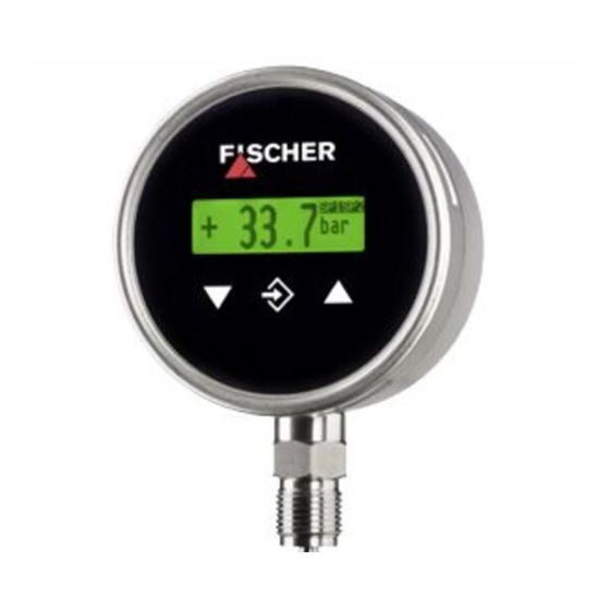
- Page 1 Operating manual MS13 Digital pressure transmitter / switch with colour change display...
- Page 2 Great care was taken when compiling the texts and illustrations; nevertheless, errors cannot be ruled out. The company FISCHER Mess- und Regeltechnik GmbH will not accept any legal responsibility or liability for this.
-
Page 3: Table Of Contents
FISCHER Mess- und Regltechnik GmbH Table of Contents Table of Contents 1 Product and functional description ...................... 4 1.1 Delivery scope ............................ 4 1.2 Performance features .......................... 4 1.3 Intended use ............................. 4 1.4 Product Overview ............................. 5 1.5 Function diagram ............................ 6 1.6 Design and mode of operation........................ 7 2 Installation and assembly.......................... 8... -
Page 4: Product And Functional Description
The MS13 complies with the state-of-the-art and is safe; it also takes into ac- count the relevant regulations and EC directives. The manufacturer will not be liable for damage arising from incorrect or improper use. -
Page 5: Product Overview
FISCHER Mess- und Regltechnik GmbH Product and functional description | 1 1.4 Product Overview All units of the series MS13 are supplied in an NG100 bayonet ring housing made of stainless steel. Process connection Code Illustration 1: Product Overview Colour change display... -
Page 6: Function Diagram
1 | Product and functional description FISCHER Mess- und Regltechnik GmbH Code Process connection Connection shanks with external thread G¼ B Connection shanks with external thread G½ B Connecting port with outer thread ¼ -18 NPT EXT Schrader® screw connection inner thread 7/16 UNF Electrical connections The power is connected using two M12 connectors. -
Page 7: Design And Mode Of Operation
FISCHER Mess- und Regltechnik GmbH Product and functional description | 1 1 Measuring cell 2 A/D converter 3 Micro-controller 4 Keyboard 5 Switching outputs 6 LCD colour change display 7 D/A converter 1.6 Design and mode of operation The device is based on a ceramic sensor element that is suitable for measuring over-pressure and under-pressure. -
Page 8: Installation And Assembly
2 | Installation and assembly FISCHER Mess- und Regltechnik GmbH 2 Installation and assembly 2.1 Generalities The instrument may only be installed and commissioned by specialized person- nel familiar with the installation, commissioning and operation of this product. Specialized personnel are persons who can assess the work they have been assigned and recognize potential dangers by virtue of their specialized training, their skills and experience and their knowledge of the pertinent standards. -
Page 9: Measuring Lines That Need To Be Connected
FISCHER Mess- und Regltechnik GmbH Installation and assembly | 2 2.2.1 Measuring lines that need to be connected The following points need to be observed when connecting the pressure line: • To ensure there is no influence on the measured values, severe bends and coils in the wire should be avoided. - Page 10 2 | Installation and assembly FISCHER Mess- und Regltechnik GmbH b) Settable damping reactor In operating mode, the damping throttle must be set so that the output signal follows the pressure changes with a delay. G½ Manometer connection SW27 Setting screw...
-
Page 11: Electrical Connections
FISCHER Mess- und Regltechnik GmbH Installation and assembly | 2 2.3 Electrical connections • By authorized and qualified specialized personnel only. • When connecting the unit, the national and international electro-technical regulations must be observed. • Disconnect the system from the mains, before electrically connecting the device. -
Page 12: Commissioning
3 | Commissioning FISCHER Mess- und Regltechnik GmbH 3 Commissioning 3.1 General All electrical supply, operating and measuring lines, and the pressure connec- tions must have been correctly installed before commissioning. All supply lines are arranged so that there are no mechanical forces acting on the device. -
Page 13: Keyboard
FISCHER Mess- und Regltechnik GmbH Commissioning | 3 3.2.2 Keyboard Illustration 14: Keyboard Page down menu Decrease value Call up menu Save value Page up menu Increase value The individual menu items and parameters can be displayed using the buttons þ... -
Page 14: Menu Levels
3 | Commissioning FISCHER Mess- und Regltechnik GmbH 3.3 Menu levels The menu levels are structured as follows: Output menu level Reception Menu Level Switch points Menu Level Input Menu Level Measuring Menu Level Output Menu Level Function Menu Level... - Page 15 FISCHER Mess- und Regltechnik GmbH Commissioning | 3 • SP1 On • SP1 Off • SP1 delay • SP1 Function Accordingly for switch point 2: • SP2 On • SP2 Off • SP2 delay • SP2 Function The function of the individual parameters is explained for both switch points us- ing Switch point 1 as an example.
- Page 16 3 | Commissioning FISCHER Mess- und Regltechnik GmbH NOTICE Response time At maximum damping it can take over 2 minutes until the pressure jump from the nominal pressure 100% to 0% is also shown as zero in the display. In many cases, unsteady readings are not a problem during normal operating mode, but this is not true for the idle state, i.e.
- Page 17 FISCHER Mess- und Regltechnik GmbH Commissioning | 3 NOTICE Adjustment of the output signal The basic measuring range (indicated on the type label) and the type of output signal (voltage / current) are not variable. The parameters MB start MB end initially define the two pressures between which the output signal will change at all.
- Page 18 3 | Commissioning FISCHER Mess- und Regltechnik GmbH 3.3.5 Menu Level Function The Function menu level is a variable menu whose appearance depends on the value of the Function parameter. There are linear, square rooted and table func- tions Linear function The input signal is linear before being sent to the display and the output.
- Page 19 FISCHER Mess- und Regltechnik GmbH Commissioning | 3 Parameter name Description Value range ∙∙∙ Value pair30 Value pair 30 The display range is defined with the parameters MB decimal pl., MB start end. The user can select the configuration freely.
- Page 20 3 | Commissioning FISCHER Mess- und Regltechnik GmbH 3.3.6 Menu Level Display The Display menu level is a variable menu whose appearance depends on the value of the colour parameter. In addition to the various colours for the back- ground lighting, there are also two auto-functions with colour switching avail- able.
- Page 21 FISCHER Mess- und Regltechnik GmbH Commissioning | 3 Basic measuring range Illustration 19: Function Auto1 MB-start Measuring range start Red-Gr. switch. Red-green switching Gr-Red switch. Green-red switching MB-end Measuring range end The parameter Hysteresis can be used to prevent fast and unwanted colour changes.
- Page 22 3 | Commissioning FISCHER Mess- und Regltechnik GmbH Parameter name Description Value range Auto1: Red-green Auto2: Red-yellow- green Lighting Lighting time 0 s, 10 … 600 s Contrast Contrast 15 … 45 Bar chart Barchart display yes, no Basic measuring range Illustration 20: Function Auto2...
- Page 23 FISCHER Mess- und Regltechnik GmbH Commissioning | 3 Parameter name Description Value range Software Info Information about the software Device type, serial number, firmware version Config Info Information about the configur- Basic measuring ation range, output signal, contacts Key numbers...
-
Page 24: Technical Data
4 | Technical Data FISCHER Mess- und Regltechnik GmbH 4 Technical Data 4.1 General Information Reference conditions (acc. to IEC 61298-1) Temperature error +15 … +25 °C Relative humidity 45 … 75 % Air pressure 86 … 106 kPa 860 … 1060 mbar... -
Page 25: Measurement Accuracy
FISCHER Mess- und Regltechnik GmbH Technical Data | 4 Switching outputs 2 potential-free relay contacts or 2 potential-free semiconductor switches (MOSFET) Relay MOSFET Progr. switching function Open contact (NO) One-pin activator (NO) Break contact (NC) One-pin deactivator (NC) Max. switching voltage 32 V AC/DC 3…32 V AC/DC... -
Page 26: Display And Operating Interface
4 | Technical Data FISCHER Mess- und Regltechnik GmbH 4.7 Display and operating interface Advertisement 4...6-digit LCD, full graphic, colour backlighting Programming Attenuation 0.0…100.0s (jump response 10/90%) Switch output Switch-off point, switch-on point, delay (0...1800s), function (NC / NO contact) Measuring range unit bar, PSI, kPa, "free unit"È, starting value, end... -
Page 27: Process Connection
FISCHER Mess- und Regltechnik GmbH Technical Data | 4 4.8.2 Process connection G½B G¼B ¼-18 NPT EXT Schrader ® Ø2 Ø5 7/16 UNF Ø9.5 ¼-18 NPT G½ Ø6 G¼ Ø17.5 G½ Code Illustration 23: Process connection Port Material G½ B Connection shanks with external thread 1.4404... -
Page 28: Order Codes
5 | Order Codes FISCHER Mess- und Regltechnik GmbH 5 Order Codes Code no. 10 11 12 Type [1.2] Measuring range converted ranges [bar] [kPa] [PSI] 0…1.6 bar 0 … 160 kPa 0 … 23.21 PSI 0…2.5 bar 0 … 250 kPa 0 …... -
Page 29: Accessories
FISCHER Mess- und Regltechnik GmbH Order Codes | 5 [6.7] Output signal Operating voltage 0 … 20 mA 24 V AC/DC 3-wire version 4 … 20 mA 24 V AC/DC 3-wire version 0 … 10 V 24 V AC/DC 3-wire version Measuring value display/switching elements 4...6-digit colour change LCD... -
Page 30: Attachments
6 | Attachments FISCHER Mess- und Regltechnik GmbH 6 Attachments Illustration 24: CE_DE_MS13 30 / 32 BA_EN_MS13... - Page 31 FISCHER Mess- und Regltechnik GmbH Attachments | 6 BA_EN_MS13 31 / 32...
- Page 32 6 | Attachments FISCHER Mess- und Regltechnik GmbH 32 / 32 BA_EN_MS13...
Need help?
Do you have a question about the MS13 and is the answer not in the manual?
Questions and answers