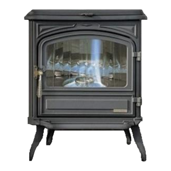
FRANCO BELGE Belfort Installation Manual
Oil stove
Hide thumbs
Also See for Belfort:
- Technical manual (17 pages) ,
- Technical manual (16 pages) ,
- Technical manual (32 pages)


Need help?
Do you have a question about the Belfort and is the answer not in the manual?
Questions and answers