Grundfos LCSE Installation And Operating Instructions Manual
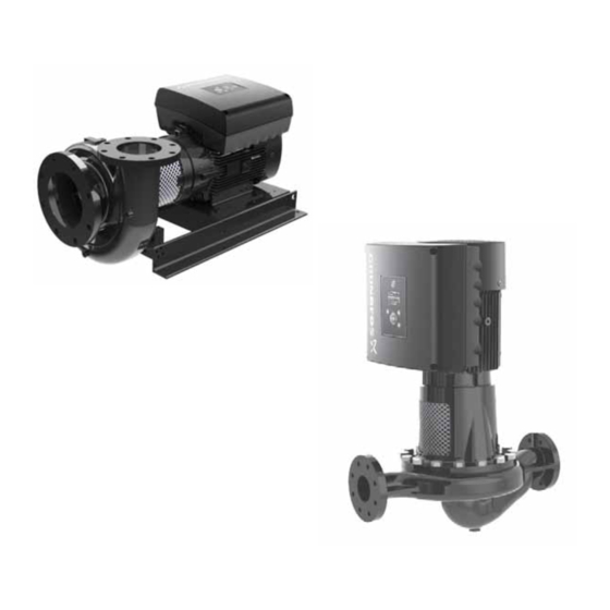
E-pumps with mle frequency-controlled
permanent-magnet motors
Hide thumbs
Also See for LCSE:
- Installation and operating instructions manual (160 pages) ,
- Installation and operating instructions manual (52 pages)

Related Manuals for Grundfos LCSE


Summary of Contents for Grundfos LCSE
- Page 1 GRUNDFOS INSTRUCTIONS LCSE, VLSE Grundfos E-pumps with MLE frequency-controlled permanent-magnet motors Installation and operating instructions...
-
Page 2: Table Of Contents
English (US) Installation and operating instructions Original installation and operating instructions 7.29 "Buttons on product" ("Enable/disable settings") 7.30 "Delete history" These installation and operating instructions describe Grundfos 7.31 "Define Home display" LCSE, VLSE. 7.32 "Display settings" Sections 1-4 give the information necessary to be able to unpack, 7.33 "Store settings"... -
Page 3: Limited Warranty
The symbols and hazard statements below may appear in Sellers obligation under this warranty is limited to repairing or Grundfos installation and operating instructions, safety instructions and service instructions. replacing, at its option, any part found to its satisfaction to be so... -
Page 4: Notes
2.2 Notes 2.3 Abbreviations and definitions The symbols and notes below may appear in Grundfos Analog input. installation and operating instructions, safety instructions and Alarm, out of range at lower limit. service instructions. Analog output. Alarm, out of range at upper limit. -
Page 5: Receiving The Product
1. Check that the product is as ordered. a wall or other fixed objects. See fig. 1. 2. Check that no visible parts have been damaged. 3. If parts are damaged or missing, contact your local Grundfos sales company. 4. Installing the product 4.1 Mechanical installation... -
Page 6: Electrical Installation
The cover must be sufficiently large to ensure that the motor is not exposed to direct sunlight, rain or snow. Grundfos does not DANGER supply covers. We therefore recommend that you have a cover built for the specific application. - Page 7 Death or serious personal injury network, make sure that you have a suitable motor - Always comply with local regulations as to cable variant. If you are in doubt, contact Grundfos. cross-sections. Single-phase supply The wires in the motor terminal box must be as short as possible.
- Page 8 10.3.2 Leakage current variant. If you are in doubt, contact Grundfos. 10.4.2 Leakage current (AC). This product can cause a direct current in the protective ground conductor.
- Page 9 For maximum torques, see section Torques, page 64. Connection terminals, LCSE and VLSE LCSE and VLSE pumps have a number of inputs and outputs enabling the pumps to be used in advanced applications where many inputs and outputs are required.
- Page 10 * If you use an external supply source, there must be a GENIbus, B GENIbus, B (-) connection to GND. Ground Fig. 8 Connection terminals, LCSE and VLSE pumps +24 V Supply +24 V Supply Supply to potentiometer and +5 V...
- Page 11 Digital input 1 is factory-set to be start-stop input where open circuit results in stop. A jumper has been factory-fitted between terminals 2 and 6. Remove the jumper if digital input 1 is to be used as external start-stop or any other external function. DANGER Electric shock Death or serious personal injury...
- Page 12 * If you use an external supply source, there must be a Grundfos Digital Sensor connection to GND. GDS RX input Fig. 9 Connection terminals, optional for LCSE and VLSE Analog input: pumps 0-20 mA / 4-20 mA 0.5 - 3.5 V / 0-5 V / 0-10 V...
- Page 13 4.2.6 Signal cables 4.2.7 Bus connection cable • Use screened cables with a cross-sectional area of minimum New installations 28 AWG and maximum 16 AWG for the external on/off switch, For the bus connection, use a screened 3-core cable with a digital inputs, setpoint and sensor signals.
-
Page 14: Installing A Communication Interface Module
4.3 Installing a communication interface module 3. Remove the securing screw (fig. 16, A). DANGER Electric shock Death or serious personal injury - Switch off the power supply to the motor and to the signal relays. Wait at least 5 minutes before starting any work on the motor. -
Page 15: Changing The Position Of The Control Panel
4.4 Changing the position of the control panel 8. Route the wires for the CIM module. See the example in fig. DANGER Electric shock Death or serious personal injury - Switch off the power supply to the motor and to the signal relays. -
Page 16: Product Introduction
The pumps have been factory-set to constant-curve control mode. You can change the control mode with R100 or Grundfos 5.1.2 Pumps with factory-fitted pressure sensor The pumps have a built-in PI controller and are set for a pressure sensor enabling the control of the outlet pressure. -
Page 17: Identification
You can identify the fitted control panel on the motor nameplate. product, and only by a Grundfos-approved installer. See fig. 28. 5.1.5 Battery A Li-ion battery is fitted in LCSE and VLSE pumps. The Li-ion battery complies with the Battery Directive (2006/66/EC). The VARIANT PB : battery does not contain mercury, lead and cadmium. -
Page 18: Grundfos Eye
5.4 Grundfos Eye The operating condition of the pump is indicated by Grundfos Eye on the control panel. See fig. 29, A. Fig. 29 Grundfos Eye Grundfos Eye Indication Description The power is off. No lights are on. The pump is not running. -
Page 19: Signal Relays
You can set the signal outputs to "Operation", "Pump running", "Ready", "Alarm" and "Warning". The functions of the two signal relays appear from the table below: Contact position of signal relays when activated "Operating Description Grundfos Eye "Pump mode" "Operation" "Ready" "Alarm" "Warning"... -
Page 20: User Interfaces
GO and other products of the same type. When you try to establish radio communication between the pump and Grundfos GO or another pump, the green indicator light in Grundfos Eye flashes. A note also appears in the pump display stating that a wireless device wants to connect to the pump. - Page 21 6.1.1 Home display Fig. 31 Example of "Home" display Pos. Symbol Description "Home" This menu shows up to four user-defined parameters. You can select parameters shown as shortcut icon , and when pressing you go directly to the "Settings" display for the selected parameter.
- Page 22 6.1.3 Menu overview for advanced control panel "Home" Multipump "Home" VLSE LCSE system ● ● ● "Status" Multipump "Status" VLSE LCSE system "Operating status" ● ● ● "Operating mode, from" ● ● ● "Control mode" ● ● ● "Pump performance"...
- Page 23 "Settings" Multipump "Settings" VLSE LCSE Section Page system Setpoint" "Setpoint" ● ● ● 7.1 " "Operating mode" Operating mode" ● ● ● 7.2 " Set manual speed" "Set manual speed" ● ● ● 7.3 " "Control mode" ● ● ●...
- Page 24 Continued from page 23. Multipump "Settings" VLSE LCSE Section Page system "Special functions" ● ● ● 7.17 "Stop function" ("Low-flow stop "Low-flow stop function" ● ● ● function") "Pipe filling function" ● ● ● 7.18 "Pipe filling function" 7.19 "Pulse flowmeter" ("Pulse "Pulse flowmeter setup"...
-
Page 25: Grundfos Go
Android or iOS-based smart device with Bluetooth connection. 6.2.1 Communication When Grundfos GO initiates communication with the pump, the indicator light in the middle of Grundfos Eye flashes green. See section 4.4 Changing the position of the control panel. - Page 26 ● "Fitted modules" ● ● "Pump 1" ● "Pump 2" ● "Pump 3" ● "Pump 4" ● Only available if an advanced functional module, type FM 300, is fitted. Only available if Grundfos GO is connected to a multipump system.
- Page 27 Multipump "Settings" VLSE LCSE Section Page system Setpoint" "Setpoint" ● ● ● 7.1 " Operating mode" "Operating mode" ● ● ● 7.2 " "Control mode" ● ● ● 7.4 "Control mode" "Pipe-filling function" ● ● ● 7.18 "Pipe filling function"...
- Page 28 7.36 "Connection code" "Unit configuration" ● ● 7.28 "Unit configuration" ("Units") Only available if an advanced functional module, type FM 300, is fitted. Only available if Grundfos GO is connected to a multipump system. Multipump "Alarms and warnings" VLSE LCSE Section...
-
Page 29: R100 Remote Control
During communication, point R100 at the control panel. When Grundfos R100 remote control. R100 communicates with the pump, the indicator light in the middle of the Grundfos Eye flashes green. See page 18. R100 offers additional possibilities of setting and status displays for the pump. - Page 30 Multipump "Installation" VLSE LCSE Section Page system "Control mode" ● ● 7.4 "Control mode" Controller 7.11 "Controller" (" "Controller" ● ● settings" Relay 7.9 "Signal relays" 1 and 2 (" "Signal relay 1 and 2" ● ● outputs" 7.29 "Buttons on product"...
-
Page 31: Description Of Functions
This menu is only available in the advanced control panel. With VLSE ● Grundfos GO, you set the speed via the "Setpoint" menu. You can set the pump speed in % of the maximum speed. When Possible operating modes: you have set the operating mode to "Manual", the pump runs at •... - Page 32 7.4.1 "Constant pressure" 7.4.2 "Constant temperature" "Constant "Constant Pump variant Pump variant pressure" temperature" LCSE ● LCSE ● VLSE ● VLSE ● We recommend this control mode if the pump is to deliver a This control mode ensures a constant temperature. Constant constant pressure, independently of the flow in the system.
- Page 33 7.4.3 "Constant differential pressure" 7.4.4 "Constant differential temperature" "Constant "Constant Pump variant differential Pump variant differential pressure" temperature" LCSE ● LCSE ● VLSE ● VLSE ● The pump maintains a constant differential pressure, The pump maintains a constant differential temperature in the independently of the flow in the system.
- Page 34 7.4.5 "Constant flow rate" 7.4.6 "Constant level" "Constant flow Pump variant "Constant level" Pump variant rate" LCSE ● LCSE ● VLSE ● VLSE ● The pump maintains a constant level, independently of the flow The pump maintains a constant flow in the system, independently rate.
- Page 35 7.4.9 "Proportional pressure" This function is only available for VLSE. "Constant other Pump variant value" "Proportional Pump variant pressure" LCSE ● LCSE VLSE ● VLSE ● Any other value is kept constant. Use this control mode if you want to control a value which is not The head of the pump is reduced at decreasing water demand available in the "Control mode"...
-
Page 36: Analog Inputs
You can set the analog inputs via the "Setup, analog input" menu. See section 7.42 "Setup, analog input". "Temperature 1" If you make the manual setting via Grundfos GO, you need to "Temperature 2" enter the menu for the analog input under the "Settings" menu. "Diff. temp., ext." Function "Ambient temp."... -
Page 37: Pt100/1000 Inputs
You can set the analog inputs via the "Setup, analog input" menu. See section 7.42 "Setup, analog input". Function If you make the manual setting via Grundfos GO, you need to Select one of these functions: enter the menu for the Pt100/1000 input under the "Settings" "Not active". •... -
Page 38: Digital Inputs/Outputs
When this function is selected, the accumulated flow can be registered. This requires the use of a flowmeter which can give "Digital inputs/outputs" Pump variant a feedback signal as a pulse per defined volume of water. LCSE ● See section 7.19 "Pulse flowmeter" ("Pulse flowmeter setup"). -
Page 39: Signal Relays" 1 And 2 ("Relay Outputs")
Pump variant (See details in section ("Relay outputs") (See details in section 7.9 "Signal relays" 1 and 2 Digital inputs" 7.7 " Relay outputs" LCSE ● (" VLSE ● • "Not active" • "Not active" • "External stop" • "Ready"... -
Page 40: Analog Output
7.10 "Analog output" The reading is a percentage of the external setpoint range. "Motor load" • "Analog output" Pump variant "Motor load" LCSE ● Signal range VLSE ● [V, mA] Whether the analog output is available or not, depends on the "0-10 V"... -
Page 41: Controller" ("Controller Settings")
Pump variant temperature ("Controller settings") LCSE* VLSE ● * You can install LCSE with an optional pressure sensor for -0.5 10 + 5L2 constant-pressure control. The pumps have a factory default setting of gain (K ) and integral time (T... -
Page 42: Operating Range
7.12 "Operating range" 7.13 "External setpoint function" "Operating range" Pump variant "External setpoint Pump variant function" LCSE ● LCSE ● VLSE ● VLSE ● Set the operating range as follows: You can influence the setpoint by an external signal, either via •... - Page 43 Example with constant curve with linear influence • "Linear with Stop" and "Linear with Min." Actual setpoint: actual input signal x (setpoint - user-set minimum – "Linear with Stop" speed) + user-set minimum speed. In the input signal range from 20 to 100 %, the setpoint is influenced linearly.
- Page 44 • "Inverse with Stop" and "Inverse with Min.". • "Influence table". The setpoint is influenced by a curve made out of two to eight – "Inverse with Stop" points. There is a straight line between the points and a In the input signal range from 0 to 80 %, the setpoint is horizontal line before the first point and after the last point.
-
Page 45: Predefined Setpoints
Fig. 65 Principle sketch showing how predefined setpoints function If all digital inputs are open, the pump stops or runs at the normal setpoint. Set the desired action with Grundfos GO or with the advanced control panel. Factory setting See section 10. -
Page 46: Limit-Exceeded Function
Pump variant function" function is activated. Resetting delay LCSE ● The resetting delay is the time from which the measured VLSE ● parameter differs from the set limit including the set hysteresis This function can monitor a measured parameter or one of the band and until the function is reset. -
Page 47: Liqtec" ("Liqtec Function")
Pump variant ("LiqTec function") • reduced wear of the shaft seals • reduced noise from operation. LCSE ● The disadvantages of enabling the "Low-flow stop function" may VLSE ● be the following: You can enable the function of the LiqTec sensors in this display. - Page 48 Factory setting "Set minimum flow" See section Set the minimum flow (Q ) in this display. This setting 10. Technical data. determines at which flow rate the system is to change from "Low-flow detection" continuous operation at constant pressure to start-stop operation. Low flow can be detected in two ways: The setting range is 5 to 30 % of rated flow.
-
Page 49: Pipe Filling Function
"Pipe filling Fixed speed of the pump during the filling phase. Pump variant function" • "filling pressure". The pressure that the pump must reach before the maximum LCSE ● filling time. VLSE ● • "max. filling time". This function is typically used in pressure-boosting applications The time in which the pump must reach the filling pressure. -
Page 50: Ramps
7.20 "Ramps" 7.21 "Standstill heating" Pump variant "Ramps" Pump variant "Standstill heating" LCSE ● LCSE ● VLSE ● VLSE ● The ramps determine how quickly the pump can accelerate and You can use this function to avoid condensation in humid decelerate during start-stop or setpoint changes. -
Page 51: Service
The factory-set interval between relubrications is stated on the bearing nameplate which is placed on the motor. The relubrication interval can be changed by a Grundfos service technician. It is possible to relubricate the bearings five times according to the preset interval. -
Page 52: Date And Time" ("Set Date And Time")
7.27 "Date and time" ("Set date and time") 7.29 "Buttons on product" ("Enable/disable settings") "Date and time" "Buttons on product" Pump variant Pump variant ("Set date and time") ("Enable/disable settings") LCSE ● LCSE ● VLSE ● VLSE ● The availability of this menu depends on the functional module... -
Page 53: Define Home Display
In this display, you can give the pump a name. In this way, you Grundfos GO can easily identify the pump when connecting with Grundfos GO. In this menu, you can store the actual settings for later use in the same pump or in other pumps of the same type. -
Page 54: Connection Code
Setting the code in Grundfos GO • "Select time format".* You can define a default connection code in Grundfos GO so that See section 7.27 "Date and time" ("Set date and time"). it automatically attempts to connect to the selected product via "Set time".*... -
Page 55: Warning Log
8. Select electrical input signal according to the sensor Pump variant "Assisted pump setup" specifications. 9. Set the desired setpoint. LCSE ● 10. Set the gain and integral time of the controller. See section VLSE ● Controller settings"... -
Page 56: Multi-Pump Setup" ("Setup Of Multi-Pump System")
18. Press [>] to continue. 19. Confirm the setting by pressing [Send]. 20. Press [Finish] in the "Setup complete" dialog box. 21. Wait for the green indicator light in the middle of Grundfos Eye to light up. - Page 57 21. Press [>] to continue. 22. Confirm the setting by pressing [Send]. 23. Press [Finish] in the "Setup complete" dialog box. 24. Wait for the green indicator light in the middle of Grundfos Eye to light up.
-
Page 58: Description Of Control Mode
Advanced control panel and wired pump connection Disabling a multipump system via Grundfos GO 1. Connect the two pumps with each other with a 3-core 1. Select the "Assist" menu. screened cable between the GENIbus terminals A, Y, B. 2. Select "Setup of multi-pump system". -
Page 59: Description Of Settings
Example: If you have set the pump to maximum speed via the digital input, the pump control panel or Grundfos GO can only set the pump to "Manual" or "Stop". The priority of the settings appears from the table below:... -
Page 60: Factory Settings
Function is disabled. Function is not available. VLSE Function Settings description on With factory-fitted Without LCSE page sensor factory-fitted sensor "Setpoint" 75 % of sensor range 75 % of sensor range 75 % of sensor range "Operating mode" "Normal" "Normal"... -
Page 61: Servicing The Product
QR code. http://net.grundfos.com/qr/i/98413121 9.2 Pump Service documentation is available in Grundfos Product Center (http://product-selection.grundfos.com/). If you have any questions, please contact the nearest Grundfos company or service workshop. 9.3 Cleaning the product WARNING Electric shock... -
Page 62: Technical Data
If the motor is to operate at ambient Recommended fuse size temperatures between 122 °F (50 °C) and 140 °F (60 °C), select an oversized motor. Contact Grundfos for further information. Motor size Minimum Maximum 10.1.3 Installation altitude... -
Page 63: Technical Data, Three-Phase Motors
10.4 Technical data, three-phase motors 10.5 Inputs/outputs Ground reference 10.4.1 Supply voltage All voltages refer to ground. All currents return to ground. • 3 x 380-500 V - 10 %/+ 10 %, 50/60 Hz, PE. Check that the supply voltage and frequency correspond to the Absolute maximum voltage and current limits values stated on the nameplate. -
Page 64: Other Technical Data
, 28-16 AWG. 15 (11) C3/C1* Use Pt100 for short wires. C1, if equipped with an external Grundfos EMC filter. Use Pt1000 for long wires. Immunity: Fulfills the requirements for industrial areas. LiqTec sensor inputs Contact Grundfos for further information. -
Page 65: Disposing Of The Product
1. Use the public or private waste collection service. Motor Speed [dB(A)] stated on [Hp (kW)] [min 2. If this is not possible, contact the nearest Grundfos company nameplate 1-phase 3-phase or service workshop. [min motors motors Dispose of the waste battery through the national collective 1500 schemes. - Page 66 This device must accept any interference, including interference that may cause undesired operation of the device. Users are cautioned that changes or modifications not expressly approved by Grundfos could void the user's authority to operate the equipment. Pour le Canada Communication radio Ce dispositif est conforme à...
- Page 67 1.4 Electrical connection 1.4.1 Conductors See section requirements, page 10. 7.2 Cable 1.4.2 Torques Maximum tightening torques for the terminals can be found in section Torques, page 64. 1.4.3 Line reactors The maximum line reactor sizes are listed below. Motor Maximum line reactor size [Hp] [mH]...
- Page 69 GRUNDFOS Kansas City GRUNDFOS Canada GRUNDFOS México 17100 West 118th Terrace 2941 Brighton Road Boulevard TLC No. 15 Olathe, Kansas 66061 Oakville, Ontario L6H 6C9 Canada Parque Industrial Stiva Aeropuerto Phone: (913) 227-3400 Phone: +1-905 829 9533 C.P. 66600 Apodaca, N.L. México...
- Page 70 99364458 1117 ECM: 1220663 www.grundfos.com www.grundfos.us...
Need help?
Do you have a question about the LCSE and is the answer not in the manual?
Questions and answers