
Related Manuals for Grundfos SQFlex 11 SQF-2


Summary of Contents for Grundfos SQFlex 11 SQF-2
- Page 1 GRUNDFOS INSTRUCTIONS Installation and op erating instructions Notice d’installation et d’entretien Instrucciones de instalación y funcionamiento...
- Page 2 Grundfos’ liability under this warranty shall be limited to repairing or replacing at Grundfos’ option, without charge, F.O.B. Grundfos’ factory or authorized service station, any product of Grundfos’ manufacture. Grundfos will not be liable for any costs of removal, installation, transportation, or any other charges which may arise in connec- tion with a warranty claim.
- Page 3 Installation and Page operating instructions Notice d’installation Page et d’entretien Instrucciones de instalación Pág. y funcionamiento...
-
Page 4: Table Of Contents
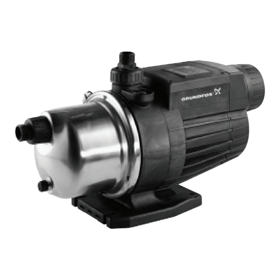
CONTENTS 1. General description Page The MQ is a compact water supply system consisting of a pump, motor, pressure tank and controller com- General description bined in an integral unit. Applications Type key The pump starts automatically when water is con- MQ pump sumed in the installation and stops when the con- sumption ceases. -
Page 5: Mq Pump
1.3 MQ pump Fig. 1 Control panel Pressure tank Discharge port Priming plug Suction port Plug Drain plug Base plate 2. Pumped liquids Thin, clean, non-aggressive liquids, not containing solid particles or fibres. 3. Technical data 3.1 Operating conditions MQ 3-35 MQ 3-45 Maximum flow rate [gpm] Maximum pressure [psi]... -
Page 6: Electrical Data
3.2 Electrical data MQ 3-35 MQ 3-45 Enclosure class IP 54 Insulation class Supply cable 6.56 ft H07RN-F with/without plug 1 x 110-120 V –10/+6%, 60 Hz 800/7.2 A 1000/9.2 A Voltage, power consumption, P 1 x 220-240 V –10/+6%, 60 Hz 850/3.7 A 1050/4.5 A 3.3 Dimensions... - Page 7 The functions of the control panel are described in the following table: Illustration Description Indicator light (red): When the indicator light is on, the pump is on standby. On/off button: The pump is started/stopped by means of the on/off button. The on/off button can also be used for manual resetting in case of an alarm condition: •...
-
Page 8: Pump Stop
4.2 Pump stop The pump is supplied with 1" NPT screwed connec- tions to be fitted in the suction and discharge ports, The pump incorporates an electronic protective func- see fig. 5. tion which will stop the pump in case of Fig. -
Page 9: Electrical Connection
6. Electrical connection Connect the mains supply cable of the pump to the electricity supply. When the cable is connected, a red The electrical connections and additional protection and a green indicator light on the control panel will be should be carried out by qualified persons in accor- on, see fig. -
Page 10: Wiring Diagram
6.2 Wiring diagram Fig. 9 Capacitor Electric motor Blue Yellow/green Ground Phase Brown => Mains Neutral Blue Black => Flow sensor Orange => Pressure switch 6.3 Winding resistance measurement Ambient temperature Motor Resistance Measuring point Winding [V/Hz] [Ω ±10%] [°C] [°F] 230/50 Main... -
Page 11: Start-Up
When the pump is started, it will begin to self-prime. If Grundfos is requested to service the pump, Grund- When the pump has been primed, it will automati- fos must be contacted with details about the pumped cally change over to normal operation. -
Page 12: Fault Finding Chart
Clean the valve or fit a new check valve. when no water is pipework is leaking or defective. consumed. If the pump does not start when the fault has been corrected, contact your pump supplier or Grundfos for further information. - Page 13 11. MQ frequently asked questions 1. What causes the MQ to start? 6. What is the maximum inlet pressure allowed in the MQ? Answer: The MQ is equipped with both an internal ow switch and pressure switch. Each of these can Answer: For both MQ 3-35 and MQ 3-45 the maxi- turn the MQ on depending on water consumption.
Need help?
Do you have a question about the SQFlex 11 SQF-2 and is the answer not in the manual?
Questions and answers