
Related Manuals for Grundfos LFE


Summary of Contents for Grundfos LFE
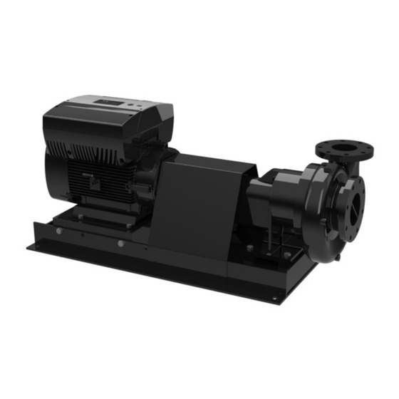
- Page 1 GRUNDFOS INSTRUCTIONS LFE, LCSE End suction frame-mounted pumps with integrated VFD End suction split coupled pumps with integrated VFD Installation and operating instructions...
- Page 2 LFE, LCSE English (US) Installation and operating instructions............3 Pump information .
-
Page 3: Table Of Contents
Extended period shutdown Maintenance Motor lubrication Pump lubrication Disassembly of pumps Seal replacement (LCSE) Wear ring replacement Reassembly of pumps Ordering parts Type LFE, cross section and parts list Type LCSE, exploded view and parts list Trouble Shooting Symptom Possible Causes... -
Page 4: Limited Warranty
Products manufactured in this manual by GRUNDFOS CBS INC. Warning (Grundfos) are warranted to the original user only to be free of defects in material and workmanship for a period of 24 months If these safety instructions are not observed, from date of installation, but not more than 30 months from date it may result in personal injury. -
Page 5: Location
E-motor. See specific sections for anti- • After pump alignment has been established (LFE), put nuts on condensation heater solutions. foundation bolts and tighten them just enough to keep the unit base plate from moving. -
Page 6: Discharge (Outlet) Piping
Avoid any high points, such as pipe loops fig. 4, that may 5.10 Shaft sealing-general comments create air pockets and throttle the system or produce erratic • Grundfos offers both mechanical seals and packed stuffing pumping. boxes as a means to seal the shaft. Pumps with stuffing boxes •... -
Page 7: Mechanical Seals
5.12 Mechanical seals 5.13 Coupling alignment (LFE) Grundfos Type LFE and LCSE pumps that are equipped with • The following anchoring and alignment procedure is typical mechanical seals are matched to conditions for which the pump and, if performed with care, should result in a smooth running, was sold. -
Page 8: Installation-Electrical
7. Operation 7.1 Priming Warning Use only qualified electricians for electrical • Grundfos Type LFE and LCSE pump is not self-priming, and installation and maintenance. must be completely primed (filled with liquid) before starting. Refer to manuals provided with electrical •... -
Page 9: Starting The Pump
6 mo 3 mo 3 mo shutdowns for the Grundfos Type LFE and LCSE pumps. If the pump will be inoperative for an extended length of time, follow Standard conditions: storage procedures in Extended Period Shutdown. 8 hours per day operation, normal or light loading, clean air, 100 •... -
Page 10: Pump Lubrication
8.2 Pump lubrication • Grundfos Type LFE pumps on horizontal bearing frames have bearing that may be sealed for life (requiring no lubrication), regreasable or oil lubricated. Approved lubricants Manufacturer Lubricant ® SHELL DOLIUM Oil level ® EXXON POLYREX SRI GREASE NLGI 2... -
Page 11: Disassembly Of Pumps
350 °F to loosen locktite. Twist sleeve off shaft (6A). 1. Complete preparations 8.3.2 Disassembly of bearing frame (LFE) 2. Back-pull rotating assembly, 3. It may be necessary to remove volute (1A) from piping, to 1. Remove slinger (13G). -
Page 12: Reassembly Of Pumps
Coupling guard must be reinstalled and in place prior to operation. 8.7 Ordering parts Grundfos Pumps has over 90 years of experience in the design, manufacture, and application of centrifugal pumps and pumping systems. Grundfos's commitment to state-of-the-art pump design and quality manufacturing assures maximum user benefits with optimum equipment life at lower cost. -
Page 13: Type Lfe, Cross Section And Parts List
8.8 Type LFE, cross section and parts list Item No. Part name Item No. Part name Item No. Part name Casing 10A* Washer, Packing 16L Plug Seal Chamber Backplate Washer, Impeller Bearing, Inboard Enclosed Impeller Gasket, Casing Bearing, Outboard Case Wear Ring... -
Page 14: Type Lcse, Exploded View And Parts List
8.9 Type LCSE, exploded view and parts list ITEM NO PART NAME ITEM NO PART NAME VOLUTE SEAL CAP O-RING SEAL CAP BASE RAIL IMPELLER MOTOR DECK CASE WEAR RING CAST IRON STAND BALANCE RING PUMP SUPPORT PUMP SHAFT MOTOR BRACKET VOLUTE SCREW SEAL CAP STUDS PUMP SHAFT SCREW... -
Page 15: Trouble Shooting
9. Trouble Shooting 9.1 Symptom Symptoms Cause Code Pump does not deliver any liquid at start-up. 1*2*3*4*5*6*7*8*9*10*11*14*16*17*22*23*24*34 Pump stops delivering liquid after start-up. 2*3*4*5*6*7*8*9*10*11*12*13*22*23*24*34 Pump overheats and/or ceases to deliver liquid. 1*3*9*10*11*21*22*27*29*30*31*33*34*40*41 Insufficient flow rate. 2*3*4*5*6*7*8*9*10*11*14*16*17*20*21*22*23*24*25*26*34 Excessive flow rate. 15*18*20*34 Discharge pressure is too high. - Page 16 Grundfos GO or wireless remote control. Indicator lights and signal relay Other settings Emergency operation (only 15-30 hp) All other settings can only be made by means of the Grundfos GO Insulation resistance or R100. Maintenance and service Important parameters such as actual value of control parameter, 27.1 Cleaning of the motor...
- Page 17 12. Mechanical installation 13.1.1 Preparation Before connecting the E-pump to the power supply, take the The pump must be secured to a solid foundation by means of issues illustrated in the figure below into consideration. bolts through the holes in the flange or baseplate. In order to retain the UL/cUL approval, follow the Note Note...
- Page 18 13.1.7 Supply voltage and power supply 13.1.8 Start/stop of pump 3 x 440-480 V - 10 %/+ 10 %, 60 Hz, PE. The number of starts and stops via the power Caution 3 x 208-230 V - 10 %/+ 10 %, 60 Hz, PE. supply must not exceed 4 times per hour.
- Page 19 13.1.10 Three-phase pumps, 3-10 hp 13.2.1 Preparation Before connecting the E-pump to the power supply, take the Group 3: Power supply (terminals L1, L2, L3) issues illustrated in the figure below into consideration. ELCB Fig. 12 Power supply-connected pump with power switch, backup fuses, additional protection and protective grounding 13.2.2 Protection against electric shock - indirect contact...
- Page 20 Over time this varistor will be worn and need to be replaced. terminals 2 and 3 using a short wire. When the time for replacement has come, Grundfos GO, R100 As a precaution, the wires to be connected to the following and PC Tool E-products will indicate this as a warning.
- Page 21 13.3 Signal cables Group 3: Power supply (terminals L1, L2, L3) • Use screened cables with a conductor cross-section of min. 28 AWG and max. 16 AWG for external on/off switch, digital input, setpoint and sensor signals. • Connect the screens of the cables to frame at both ends with good frame connection.
- Page 22 * Common ground for both pressure and temperature signal. * Power supply (screened cable): SELV or PELV. * Grundfos will not be liable for damage or wear to products caused by abnormal operating conditions, accident abuse, Fig. 18 Electrical connections...
- Page 23 13.5 Bus connection cable 14. Modes Grundfos E-pumps are set and controlled according to operating 13.5.1 New installations and control modes. For the bus connection, use a screened 3-core cable with a conductor cross-section of 28-16 AWG. 14.1 Overview of modes •...
- Page 24 14.3 Control mode 16. Setting by means of control panel 14.3.1 Pumps without factory-fitted sensor Proportional pressure The pump head is reduced at decreasing water demand and The pumps are factory-set to control mode uncontrolled. increased at rising water demand. See fig. 25. In control mode uncontrolled, the pump will operate according to This control mode is especially suitable in systems with relatively the constant curve set, fig.
- Page 25 (top light field flashes). When the top light field is on, press 3 seconds until the light field starts flashing. The pump is designed for wireless communication with Grundfos To return to uncontrolled or controlled operation, press remote control R100.
- Page 26 0. GENERAL 1. OPERATION 2. STATUS 3. INSTALLATION 17.1.1 17.2.1 17.3.1 17.3.7 17.1.2 17.2.2 17.3.2 17.3.7 17.1.3 17.2.3 17.3.3 17.3.8 17.1.3 (1) 17.2.4 17.3.4 (3) 17.3.9 17.1.4 17.2.5 17.3.4 - 1 (2) 17.3.10 17.2.6 17.3.4 - 2 (2) 17.3.11 17.1.4 (1) 17.2.7 (2) 17.3.5 17.3.12...
- Page 27 Displays in general 17.1.2 Operating mode In the following explanation of the functions, one or two displays are shown. One display Pumps without or with factory-fitted sensor have the same function. Two displays Set one of the following operating modes: Pumps without or with factory-fitted pressure sensor have •...
- Page 28 17.2 Menu STATUS Warning (only three-phase pumps) The displays appearing in this menu are status displays only. It is not possible to change or set values. The displayed values are the values that applied when the last communication between the pump and the R100 took place. If a status value is to be updated, point the R100 at the control panel and press "OK".
- Page 29 17.2.5 Power input and power consumption 17.2.9 Time till replacement of motor bearings When the motor bearings have been relubricated a prescribed number of times stored in the controller, the display in section 17.2.8 Time till relubrication of motor bearings on page 29 will be replaced by the display below.
- Page 30 The table below shows the suggested controller settings: How to set the PI controller For most applications, the factory setting of the controller constants K and T will ensure optimum pump operation. However, in some applications an adjustment of the controller System/application Heating Cooling...
- Page 31 ® • Active • a Grundfos Liqtec dry-running sensor • Not active. • a pressure switch installed on the suction side of a pump When set to Not active (locked), the buttons do not function. Set •...
- Page 32 17.3.8 Stop function 2. Flow switch When the digital input is activated for more than 5 seconds because there is low flow, the speed will be increased until the stop pressure (actual setpoint + 0.5 x ΔH) is reached, and the pump will stop.
- Page 33 Diaphragm tank The stop function requires a diaphragm tank of a certain minimum size. The tank must be installed immediately after the pump and the precharge pressure must be 0.7 x actual setpoint. Recommended diaphragm tank size: Rated flow of Typical diaphragm ΔH pump...
- Page 34 3. Use Grundfos R100 to set the duty/standby to Not active in the installation menu. 4. Use Grundfos R100 to set the Operating mode to Stop in the operation menu. 5. Use Grundfos R100 to set the other displays as required for the pump application (such as setpoint).
- Page 35 17.3.12 Operating range 17.3.14 Confirming relubrication/replacement of motor bearings (only three-phase pumps) How to set the operating range: This function can be set to these values: • Set the min. curve within the range from max. curve to 12 % of maximum performance.
- Page 36 17.4 Typical display settings for constant-pressure E-pumps 1. OPERATION 2. STATUS 3. INSTALLATION 17.1.1 17.2.1 17.3.1 17.3.7 17.1.2 17.2.2 17.3.2 17.3.7 17.1.3 17.2.3 17.3.3 17.3.8 17.1.3 (1) 17.2.4 17.3.4 - 1 (2) 17.3.9 17.2.5 17.3.4 - 2 (2) 17.3.10 17.2.6 17.3.5 17.3.11 17.2.7...
- Page 37 17.5 Typical display settings for analog-input E-pumps 1. OPERATION 2. STATUS 3. INSTALLATION 17.1.1 17.2.1 17.3.1 17.3.7 17.1.2 17.2.2 17.3.2 17.3.7 17.1.3 17.2.3 17.3.3 17.3.8 17.1.3 (1) 17.2.4 17.3.4 - 1 (2) 17.3.9 17.2.5 17.3.4 - 2 (2) 17.3.10 17.2.6 17.3.5 17.3.11 17.2.7...
- Page 38 Shows the control mode of the When Grundfos GO Remote communicates with the pump, the Control mode product. indicator light in the middle of the Grundfos Eye will flash green. Actual setpoint Communication must be established using one of these Shows the actual setpoint value.
- Page 39 18. Setting by means of PC Tool E-products Priority of settings with bus communication Special setup requirements differing from the settings available Control panel External via the R100 require the use of Grundfos PC Tool E-products. Priority or R100 signals communication This again requires the assistance of a Grundfos service technician or engineer.
- Page 40 20.2 Digital input In control mode controlled, the setpoint can be set externally within the range from the lower value of the sensor measuring By means of the , one of the following functions can be selected range to the setpoint set on the pump or by means of the R100. for the digital input: •...
- Page 41 22. Bus signal The pump supports serial communication via an RS-485 input. The communication is carried out according to Grundfos bus protocol, GENIbus protocol, and enables connection to a building management system or another external control system. Operating parameters, such as setpoint, operating mode, etc. can be remote-set via the bus signal.
- Page 42 The functions of the two indicator lights and the signal relay are as shown in the following table: Indicator lights Signal relay activated during: Fault/Alarm, Description Operation Warning Pump Fault (red) Operating Ready (green) running Relubricate The power supply has been switched off. Permanently The pump is operating.
- Page 43 25. Emergency operation (only 15-30 hp) 3. Connect the leads as shown in fig. 47. Warning Never make any connections in the pump terminal box unless all electric supply circuits have been switched off for at least 5 minutes. Note for instance that the signal relay may be connected to an external supply which is still connected when the power supply is disconnected.
- Page 44 When it is time to replace the varistor, E-pumps using high voltage megging equipment, Grundfos GO, R100 and PC Tool E-products will indicate this as a as this may damage the built-in electronics. warning.
- Page 45 Maximum cable length: 1640 ft (500 m). Screened cable: 20-16 AWG (0.5 - 1.5 mm Bus input Maximum cable length: 1640 ft (500 m). Grundfos bus protocol, GENIbus protocol, RS-485. Screened 3-core cable: 28-16 AWG (0.2 - 1.5 mm Maximum cable length: 1640 ft (500 m).
- Page 46 CISPR11, group 2, class A, and may be installed in Max. load: 40 mA. industrial areas (second environment). Short-circuit protected. If equipped with an external Grundfos EMC filter, the Signal relay output motors are category C2, corresponding to CISPR11, Potential-free changeover contact.
- Page 47 1.7 ft-lbs (2.3 Nm) 1. Use the public or private waste collection service. Relay, M2.5: 0.4 ft-lbs (0.5 Nm) 2. If this is not possible, contact the nearest Grundfos company Input control, M2: 0.15 ft-lbs (0.2 Nm) or service workshop. 30.1.3 Line reactors Max.
- Page 51 Grundfos CBS Inc. 902 Koomey Road Brookshire, TX 77423 USA Phone: 281-994-2700 Toll Free: 1-800-955-5847 Fax: 1-800-945-4777 www.grundfosexpresssuite.com...
- Page 52 98669637 0714 ECM: 1138497 www.grundfos.com www.grundfos.us...
Need help?
Do you have a question about the LFE and is the answer not in the manual?
Questions and answers