Atmel ATDH2200E User Manual
Fpga configurator programming kit (enhanced)
Hide thumbs
Also See for ATDH2200E:
- User manual (27 pages) ,
- User manual (21 pages) ,
- User manual (27 pages)
Table of Contents
Advertisement
Quick Links
Features
Hardware
•
Supports Programming of all AT17LV, AT17N, and AT17F Series Devices
•
Connection to Allow In-System Programming (ISP)
•
Runs off Portable 9V DC Power Supply
•
5.0V and 3.3V Supply
Software
•
CPS – Configurator Programming System
•
GUI-based Interface
®
•
Supports Windows
98/2000/XP and Windows NT
•
Online Help
•
Supports Programming Reset Polarity
•
Verification Routines to Validate Programming
•
Accepts HEX, MCS, POF, RBF and BST File Formats
System Contents
•
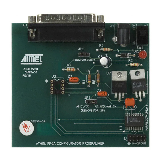
ATDH2200 Programming Board
•
ATDH2222 20-pin PLCC Adapter
•
ATDH2200E Datasheet
•
ATDH2200E Programming Kit User Guide
•
10-pin Ribbon Cable for ISP
•
9V DC, 500 mA, 2.1 mm Center Positive/Negative Power Supply (for US customers
only)
•
Sample AT17LV Devices
Description
The ATDH2200E allows designers to quickly and economically program Atmel's family
of AT17 series FPGA Configuration Memories. The system also provides support for
new devices in the AT17 series Configurator prior to Third Party Programmer support
being available. This is a truly portable solution that allows engineers to work from
their lab bench or office.
®
FPGA
Configurator
Programming
Kit (Enhanced)
ATDH2200E
Rev. 0642G–CNFG–3/09
1
Advertisement
Table of Contents

Related Manuals for Atmel ATDH2200E


Summary of Contents for Atmel ATDH2200E
- Page 1 Sample AT17LV Devices Description The ATDH2200E allows designers to quickly and economically program Atmel’s family of AT17 series FPGA Configuration Memories. The system also provides support for new devices in the AT17 series Configurator prior to Third Party Programmer support being available.
- Page 2 1. Pin 10 activates SER_EN on target board. 2. NC stands for no connection. The ATDH2200E programming board has a 10 pin header (0.1" spacing) to facilitate in-system programming (Figure 2) of the AT17 parts. The control signals generated by the software are fed to the header, as well as to socket U3 on the board.
- Page 3 ATDH2200E Related Documents • ATDH2200E Programming Kit User Guide • AT17 Series datasheet • Programming Specification for Atmel’s FPGA Configuration memories • In-System Programming Cascaded Configurators • AT17A Series datasheet Adapters Available for the • ATDH2222 – 20-lead PLCC adapter (supplied with kit) ATDH2200E •...
- Page 4 Schematics Programming Connections ATDH2200E 0642G–CNFG–3/09...
- Page 5 ATDH2200E Power Supply Generation 0642G–CNFG–3/09...
- Page 6 Disclaimer: The information in this document is provided in connection with Atmel products. No license, express or implied, by estoppel or otherwise, to any intellectual property right is granted by this document or in connection with the sale of Atmel products. EXCEPT AS SET FORTH IN ATMEL’S TERMS AND CONDI- TIONS OF SALE LOCATED ON ATMEL’S WEB SITE, ATMEL ASSUMES NO LIABILITY WHATSOEVER AND DISCLAIMS ANY EXPRESS, IMPLIED OR STATUTORY...
- Page 7 Mouser Electronics Authorized Distributor Click to View Pricing, Inventory, Delivery & Lifecycle Information: Atmel ATDH2200E- ATDH2222- Microchip ATDH2200E...
Need help?
Do you have a question about the ATDH2200E and is the answer not in the manual?
Questions and answers