Table of Contents
Advertisement
Quick Links
Advertisement
Table of Contents

Related Manuals for Aerotech MPS75SLE-025


Summary of Contents for Aerotech MPS75SLE-025
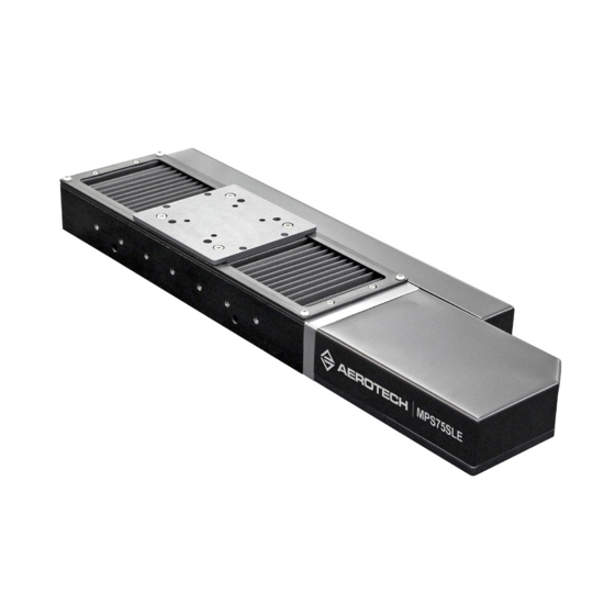
- Page 1 MPS75SLE Hardware Manual Revision: 1.00.00...
- Page 2 This manual contains proprietary information and may not be reproduced, disclosed, or used in whole or in part without the express written permission of Aerotech, Inc. Product names mentioned herein are used for identification purposes only and may be trademarks of their respective companies.
-
Page 3: Table Of Contents
3.4. Limits, Marker, and Machine Direction 3.5. Motor and Feedback Phasing Chapter 4: Maintenance 4.1. Service and Inspection Schedule 4.2. Cleaning and Lubrication 4.2.1. Bellows Removal for Re-Lubrication 4.3. Bellows Installation 4.4. Troubleshooting Appendix A: Warranty and Field Service Appendix B: Revision History Index www.aerotech.com... -
Page 4: List Of Figures
Slide the Stage Carriage and Bellow Compression Figure 4-3: Motor Cover Screw Location Figure 4-4: Bellows Support Rods Figure 4-5: Secure the Bellows Support Rods Figure 4-6: Attach the Bellows Figure 4-7: Attach the Bellows Cover Figure 4-8: Attach the Bellows Tabletop www.aerotech.com... -
Page 5: List Of Tables
MPS75SLE Series Mechanical Specifications Table 3-1: Connector Pin Assignments (DC Motor) Table 3-2: Encoder Connector Pin Assignments (DC Motor) Table 3-3: Connector Pin Assignments (Stepper Motor) Table 3-4: Feedback Specifications Table 3-5: Motor Specifications Table 3-6: Encoder Specifications Table 4-1: Troubleshooting www.aerotech.com... - Page 6 Table of Contents MPS75SLE Hardware Manual This page intentionally left blank. www.aerotech.com...
-
Page 7: Safety Procedures And Warnings
Read this manual in its entirety before installing, operating, or servicing this product. If you do not understand the information contained herein, contact an Aerotech representative before proceeding. Strictly adhere to the statements given in this section and other handling, use, and operational information given throughout the manual to avoid injury to you and damage to the equipment. - Page 8 Electrical Safety MPS75SLE Hardware Manual This page intentionally left blank. viii www.aerotech.com...
-
Page 9: Ec Declaration Of Incorporation
MPS75SLE Hardware Manual Declaration of Conformity EC Declaration of Incorporation Manufacturer: Aerotech, Inc. 101 Zeta Drive Pittsburgh, PA 15238-2897 herewith declares that the product: MPS75SLE Stage is intended to be incorporated into machinery to constitute machinery covered by the Directive 2006/42/EC as amended;... - Page 10 Declaration of Conformity MPS75SLE Hardware Manual This page intentionally left blank. www.aerotech.com...
-
Page 11: Chapter 1: Overview
Overview Chapter 1: Overview N O T E : Aerotech continually improves its product offerings; listed options may be superseded at any time. All drawings and illustrations are for reference only and were complete and accurate as of this manual’s release. Refer to www.aerotech.com for the most up-to-date information. -
Page 12: Environmental Specifications
Altitude Operating: 0 m to 2,000 m (0 ft to 6,562 ft) above sea level Contact Aerotech if your specific application involves use above 2,000 m or below sea level. Vibration Use the system in a low vibration environment. -
Page 13: Basic Specifications
Overview 1.3. Basic Specifications N O T E : Aerotech continually improves its product offerings; listed options may be superseded at any time. All drawings and illustrations are for reference only and were complete and accurate as of this manual’s release. Refer to www.aerotech.com for the most up-to-date information. -
Page 14: Vacuum Operation
MPS75SLE Hardware Manual 1.4. Vacuum Operation Aerotech can specially prepare the MPS75SLE series stage for operation in vacuum environments. As part of this preparation, attention to detail during modification, cleaning, and assembly results in stages with optimal performance in vacuum applications. This section will outline preparation techniques for stages that... -
Page 15: Chapter 2: Mechanical Specifications And Installation
MPS75SLE to stabilize to room temperature will ensure that all of the alignments, preloads, and tolerances are the same as they were when tested at Aerotech. Use compressed nitrogen or clean, dry, oil-less air to remove any dust or debris that has collected during shipping. Set the MPS75SLE on a smooth, flat, and clean surface. -
Page 16: Dimensions
N O T E : All drawings and illustrations are for reference only and were complete and accurate as of this manual’s release. The most recent system drawings and schematics can be found on your software DVD or on www.aerotech.com. 33 TYP... -
Page 17: Figure 2-2: Mps75Sle With Bellows Dimensions
DAMAGE TO STAGE CAN RESULT DETAIL A SCALE 1 : 2 DIMENSIONS: MILLIMETERS X NOMINAL X ELECTRICAL X MECHANICAL BASIC MODEL TRAVEL LIMIT TRAVEL LIMIT TRAVEL MPS75SLE-025 68.5 MPS75SLE-050 83.5 MPS75SLE-075 98.5 MPS75SLE-100 113.5 Figure 2-2: MPS75SLE with Bellows Dimensions www.aerotech.com... -
Page 18: Figure 2-3: Mps75Sle Mounting Plate Dimensions
50.8 MP-MPS75SL-050 11.3 6.8 SLOT 7.1 THRU M4x0.7 HELICOIL 8 (4) PLACES (8) PLACES 50.8 MP-MPS75SL-025 101.6 11.3 6.8 SLOT 7.1 THRU M4x0.7 HELICOIL 8 (4) PLACES (8) PLACES 50.8 DIMENSIONS: MILLIMETERS Figure 2-3: MPS75SLE Mounting Plate Dimensions Chapter 2 www.aerotech.com... -
Page 19: Figure 2-4: Mps75Sle Hdz Angle Bracket Dimensions
MPS75SLE Hardware Manual Mechanical Specifications and Installation 4.5 THRU ALL 8 TO DEPTH SHOWN (8) PLACES M4X0.7 HELICOIL THRU ALL (22) PLACES 17.5 12.5 23.5 12.5 23.5 20.5 8 TYP DIMENSIONS: MILLIMETERS Figure 2-4: MPS75SLE HDZ Angle Bracket Dimensions www.aerotech.com Chapter 2... -
Page 20: Securing The Stage To The Mounting Surface
Additional mounting holes are hidden under the stage table and should only be used for mounting XY assemblies or, in special cases, when advised to by Aerotech. Securing the stage using the inner mounting holes requires special instructions, refer to Section 2.3.1. -
Page 21: For Xy Assemblies And Special Cases
4. Mount the stage to the base using the remaining mounting holes with M4 SHCS. If the stage is equipped with optional bellows, refer to Section 4.2.1. for bellows disassembly instructions. Carefully slide the tabletop to reveal all [QTY 8] of the mounting holes. Figure 2-6: Access To All Mounting Holes www.aerotech.com Chapter 2... -
Page 22: Attaching The Payload To The Stage
N O T E : Stages that ship with Aerotech controls are often tuned with a representative payload based on the information provided at the time of order. If the stage is started up without a payload, the servo gains provided by Aerotech with the shipment may not be appropriate and servo instability can occur. -
Page 23: Figure 2-8: Stage Orientations
Figure 2-9 or the following equation: (Axial Load) (LeadofScrew) Torque (PreloadTorque) π (Efficiency) Where: Lead of Screw = see Table 1-3 Efficiency = .90 for ball-screws Moving Mass = 0.3 kg Preload Torque = 18 Nmm www.aerotech.com Chapter 2... -
Page 24: Figure 2-9: Torque Required To Turn Ball-Screw In Vertical Orientation
Mechanical Specifications and Installation MPS75SLE Hardware Manual Load-Torque Plot MPS75SL-SM and -DC 30.00 25.00 20.00 15.00 10.00 5.00 0.00 Applied Axial Load (kg) Figure 2-9: Torque Required to Turn Ball-Screw in Vertical Orientation Chapter 2 www.aerotech.com... -
Page 25: Chapter 3: Electrical Specifications And Installation
Aerotech motion control systems are adjusted at the factory for optimum performance. When the MPS75SLE is part of a complete Aerotech motion control system, setup usually involves connecting a stage to the appropriate drive chassis with the cables provided. Labels on the system components usually indicate the appropriate connections. -
Page 26: Motor And Feedback Connectors
The MPS75SLE comes from the factory completely wired and assembled. Each MPS75SLE is shipped with documentation regarding the wiring, controller interface connectors, and specifications. N O T E : Refer to the other documentation accompanying your Aerotech equipment. Call your Aerotech representative if there are any questions on system configuration. -
Page 27: Table 3-1: Connector Pin Assignments (Dc Motor)
CCW / - Limit Cosine Sine Marker +5 V power supply input Stage ID CW / + Limit Pins not shown are reserved. Mating Connector Aerotech P/N Third Party P/N Backshell ECK00656 Amphenol #17E-1726-2 Connector ECK00300 FCI DB25S064TLF www.aerotech.com Chapter 3... -
Page 28: Table 3-2: Encoder Connector Pin Assignments (Dc Motor)
Sine-N Marker-N Encoder Common Encoder Common Cosine Sine Marker +5 V power supply input Pins not shown are reserved. Mating Connector Aerotech P/N Third Party P/N Backshell ECK00656 Amphenol #17E-1726-2 Connector ECK00300 FCI DB25S064TLF Table 3-3: Connector Pin Assignments (Stepper Motor) -
Page 29: Motor And Feedback Wiring
Shielded cables are required for the motor and feedback connections. THIRD PARTY CONTROLLER STAGE MOTOR CONNECTIONS CASE CASE Pull-Up Pull-Up +LIMIT -LIMIT COSINE COSINE-N SINE SINE-N MARKER MARKER-N Typical CASE CASE Both Encoders Figure 3-1: DC Motor and Feedback Wiring www.aerotech.com Chapter 3... -
Page 30: Figure 3-2: Stepper Motor And Feedback Wiring
Electrical Specifications and Installation MPS75SLE Hardware Manual THIRD PARTY CONTROLLER STAGE ØA Return ØA MOTOR ØB CONNECTIONS ØB Return ØA ØB CASE CASE CASE Pull-Up Pull-Up +LIMIT -LIMIT CASE CASE Figure 3-2: Stepper Motor and Feedback Wiring Chapter 3 www.aerotech.com... -
Page 31: Motor And Feedback Specifications
Requires external pull-up to +5 V (10 kΩ recommended) If the MPS75SLE is driven beyond the electrical limit, it will encounter a mechanical stop. Impacting the mechanical stop could cause damage to the stage even at low speeds. www.aerotech.com Chapter 3... -
Page 32: Table 3-5: Motor Specifications
20 um fundamental 0.05 um with LTX100 option, Amplified sine (-AS) olutions option allows for electronic resolutions below 1 nm 1. For optimum performance, Aerotech recommends using 0.025 µm as the highest-resolution when using the linear encoder as part of the servo feedback loop (ex: dual-loop). Chapter 3... -
Page 33: Limits, Marker, And Machine Direction
Electrical Specifications and Installation 3.4. Limits, Marker, and Machine Direction Aerotech stages are configured to have positive and negative "machine" directions. The machine direction defines the phasing of the feedback and motor signals and is dictated by the stage wiring (refer to Section 3.5. -
Page 34: Motor And Feedback Phasing
Clockwise (CW) (+ Machine Direction) SIN-N 0° 90° 180° 270° 360° 450° 540° 630° 720° 810° COS-N 0° 90° 180° 270° 360° 450° 540° 630° 720° 810° MRK-N Positive MOVE (Clockwise) Figure 3-5: Encoder Phasing Reference Diagram (Standard) Chapter 3 www.aerotech.com... -
Page 35: Chapter 4: Maintenance
Re-tighten loose connectors. Replace or repair damaged cables. Clean the MPS75SLE and any components and cables if needed. Repair any damage before operating the MPS75SLE. Inspect and perform an operational check on all safeguards and protective devices www.aerotech.com Chapter 4... -
Page 36: Cleaning And Lubrication
W A R N I N G : Further disassembly of the stage is not recommended because proper assembly and calibration can only be done at the factory. In addition, a laser interferometer is required for post assembly verification to maintain warranties. Contact Aerotech for more information. - Page 37 9. Repeat steps 1 through 7 for any areas covered by the original table position. 10. Restore power to the stage; drive the stage table back to its original position to redistribute lubricants. www.aerotech.com Chapter 4...
-
Page 38: Bellows Removal For Re-Lubrication
5. Move the stage carriage to the opposite end of travel and repeat the process on the newly exposed track. 6. After you have completed re-lubrication, reattach the bellows to the stage end plates and restore power to the stage. Chapter 4 www.aerotech.com... -
Page 39: Bellows Installation
Screw (2) M4 setscrews in the same two holes to push the bellow support rods from the ends – do not over tighten or the rods will bow. Figure 4-4: Bellows Support Rods www.aerotech.com Chapter 4... -
Page 40: Figure 4-5: Secure The Bellows Support Rods
5. Attach the bellows to the ends of the stage and to the carriage using (8) M2 socket head cap screws. Ensure that the bellows are aligned to the stage travel. Figure 4-6: Attach the Bellows 6. Attach the bellows cover using (4) M3 button head cap screws. Figure 4-7: Attach the Bellows Cover Chapter 4 www.aerotech.com... -
Page 41: Figure 4-8: Attach The Bellows Tabletop
8. Re-install the motor cover (refer to Figure 4-3) ensuring that no wires are pinched or in the way. Do not over-tighten the screws that secure the motor cover because the cover is made of thin material and could become damaged. www.aerotech.com Chapter 4... -
Page 42: Troubleshooting
Controller trap or fault. See controller documentation. Stage moves uncontrollably Encoder (sine and cosine) signals connections. See Chapter 3 Controller documentation. Motor Connections. See Chapter 3 and Controller documentation. Stage oscillates or squeals Gains misadjusted. See Controller documentation. Encoder signals. See Controller documentation. Chapter 4 www.aerotech.com... -
Page 43: Appendix A: Warranty And Field Service
Aerotech makes no warranty that its products are fit for the use or purpose to which they may be put by the buyer, whether or not such use or purpose has been disclosed to Aerotech in specifications or drawings previously or subsequently provided, or whether or not Aerotech’s... - Page 44 Aerotech's approval. On-site Warranty Repair If an Aerotech product cannot be made functional by telephone assistance or by sending and having the customer install replacement parts, and cannot be returned to the Aerotech service center for repair, and if Aerotech determines the problem could be warranty-related, then the following policy applies:...
-
Page 45: Appendix B: Revision History
MPS75SLE Hardware Manual Revision History Appendix B: Revision History Revision Date General Information 1.00.00 April 27, 2015 New Manual www.aerotech.com Appendix B... - Page 46 Revision History MPS75SLE Hardware Manual This page intentionally left blank. Appendix B www.aerotech.com...
-
Page 47: Index
Dimensions Securing the Stage to the Mounting Surface Encoder Specifications Service Schedule Shimming grease 4,26 solvents Guidelines Specifications stage distortion HDZ Angle Bracket Dimensions Stepper Motor Pinout Humidity Temperature Effects inspect thermal expansion coefficient Inspection Schedule www.aerotech.com Index... - Page 48 Index MPS75SLE Hardware Manual Vacuum vacuum guidelines Vacuum Guidelines Vibration Warranty and Field Service Index www.aerotech.com...
Need help?
Do you have a question about the MPS75SLE-025 and is the answer not in the manual?
Questions and answers