Table of Contents
Advertisement
Quick Links
Download this manual
See also:
User Manual
Advertisement
Table of Contents

Related Manuals for ViTiny DiGi UM06


Summary of Contents for ViTiny DiGi UM06
- Page 1 User’s Guide DiGi Microscope Version 1.1A...
-
Page 3: Table Of Contents
Content Products Introduction ......2 Packing Contents ......2 IR remote controller ....2 Microscope introduction: ..10 Microscope focus ....... 13 Microscope accessory....16 Printed Notice ........17 Maintenance ......17 Product Specification ....18 Safety Instructions ..... 19... -
Page 4: Products Introduction
1. Product Introduction 1.1 Packing Contents The box contains 1 microscope and 10 accessories. The Object Lens 4X is already assembled onto microscope; if it needs to be changed, please refer to Section 1.5. Item Q’ty Item Q’ty DiGi Microscope White Balance Card HDMI Cable Calibrator... - Page 5 (4) Manual focus :Zooms in; speed increases when held. (4-1) Zoom in :Zooms out; speed increases when held. (4-2) Zoom out :zoom in by steps. (4-3) Step zoom in :zoom out by steps. (4-4) Step zoom out Microscope remote controller Buttons for common use...
- Page 6 Buttons for PC CAM mode Buttons for HDMI mode 1.2.2 Buttons for PC CAM The following buttons are used only for PC Cam mode. :When in PC CAM mode, the USB cable must connect to a PC and (1) PC CAM microscope.
- Page 7 :Takes a 5M picture and delivers it to the application program. (3) Snapshot 1.2.3 Buttons for HDMI The following buttons are used only for HDMI mode. : When in HDMI mode, the HDMI cable must connect with the screen (1) HDMI and microscope.
- Page 8 1.2.1-(2) and Section 1.2.3-(7). (2-5) SHARPNESS: [ON] Sharpens the image. [OFF] Smooths the image. (2-6) STATUS BAR: [ON] Displays the status bar on the top of screen. For more on the status bar, please refer to Section 1.2.3-(9). ...
- Page 9 :Changes the image ratio or Field of View. The original image (8) Video Ratio size is a 5M image (2592*1944) output. (8-1) 4/3F:Formats the image to fit a 4:3 screen size (1440*1080) by proportionally reducing the input image to fit the screen. (8-2) 16/9S:Formats the image to fit a 16:9 screen size (1920*1080) by scaling the input image width and trimming the height to fit the screen.
- Page 10 (2595*1944). The FOV becomes smaller and magnification becomes higher. (9) Status Bar : On/Off Displays or hides the status bar. Each color represents different information. (9-1) ZOOM:Zoom path, totals 15 sections. (9-2) FOV:Field of View, display image on the effective horizontal size of screen.
- Page 11 (9-3) M:(Magnification) The magnification size will change depending on the lens position, screen size, and image ratio. For more information, please refer to Section 1.4.2. (9-4) D:(Distance) Refers to the distance from object lens to the object. (9-5) EV:(Exposure Value) Please refer to Section 1.2.3-(7). (9-6) LED:(LED Levels) Please refer to Section 1.2.1-(2).
-
Page 12: Microscope Introduction
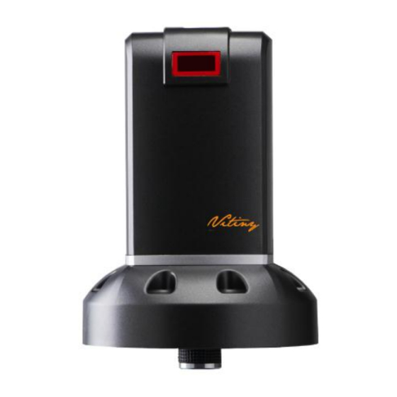
again to return to preview. (12) Sharpness : On/Off sharpness mode. Please refer to Section 1.2.3-(2). 1.3 Microscope introduction: 1.3.1 IR Remote Area/Indicator When both the HDMI and USB indicator lights are on, the microscope is turned off. Caution: Please remove the transparent protection sheet on the IR receiver area. ○... - Page 13 Power/USB/HDMI port (1) Power○ : Power supply is only compatible with the cord in the box. ○ (2) USB○ : The USB cable is used to connect the microscope to a PC to access the application program. When the device is in PC Cam mode, connect the microscope to a PC through the USB cable from the box.
- Page 14 :The HDMI port is used to connect the microscope to a screen. When (3) HDMI○ the device is in HDMI mode, connect the microscope to the screen using the HDMI cable from the box. * For TV screen connections, make sure to choose the homologous image ratio and format.
-
Page 15: Microscope Focus
1.3.3 LED/ Light socket (1) LED○ : Provides luminance for object lens 4x; total 30 LEDs (6 LEDS have wider angles as shown in the figure). (2) Light socket○ : Provides luminance for object lens 10x. (Optional accessory) ○ ○ 1.4 Microscope Focus There are two ways to focus. - Page 16 the application program to focus the image. (2) Fixed image sensor position (2-1) In HDMI mode, the status bar will show on the screen (please refer to Section 1.2.3-(9)). Use the remote controller to adjust the image sensor position based on magnification size, FOV, or distance height. (2-2) In PC CAM mode, choose the desired height or FOV from the drop down list in the application program (see figure below).
- Page 17 1.4.2 Magnification chart 15 image sensor positions had set from the whole area, the image sensor position tells the magnification size, field of view, or height. The below chart is measured on 21.5” screen, it’s only a reference data, might not be accurate enough.
-
Page 18: Microscope Accessory
(2) Object lens 10X, focus distance from 4.5mm to 7.7mm (0.177 to 0.303inch. Object lens 10X on 21.5” screen Sensor position Distance (mm) 7.70 7.10 6.70 6.40 6.10 5.89 5.60 5.41 F,S FOV (mm) 1.39 1.30 1.21 1.14 1.07 1.01 0.96 0.91 C FOV (mm) -
Page 19: Printed Notice
2. Printed Notice Please read the following information before operating. 2.1 Maintenance Please abide by the following rules while storing or using this product: 2.1.1 Keep dry: do not place the product in a humid environment. Dry surroundings help extend the life of the product. 2.1.2 Avoid temperature shock: temperature shock (for example, taking the product into a warm room from a cold environment) will cause internal condensation inside the machine. -
Page 20: Product Specification
IR remote controller/PC(application program) control adaptor Power (input:DC 5.0V/2.0A input:AC 100-240V 50/60Hz) supplier Electric 5V/1200mA Consumption Size 106(L)×106(W)×152(T) mm Weight Host weight around 310 grams Temperature -5℃ ~ 50℃; Humidity-lower than 85% (No Operation environment Condensation) For any changes, please visit http://www.vitiny.com... -
Page 21: Safety Instructions
Please remove the power supply from the microscope when not in use. Do not disassemble the machine for inspection. For any problems occurring in the machine itself, please power off the device and contact us through e-mail: mltc@vitiny.com... - Page 22 (1) Service fees (including transportation fees) of product inspection. (2) Repair fees. (3) Fees of replaced parts ViTiny Service Center Tel: 07-657-9551 Fax: 07-657-9561 Address: 10 F., No.1, Section 1, Syuecheng Road, Dashu District, Kaohsiung City 840, Taiwan (R.O.C.) Website: http://www.vitiny.com...
- Page 23 ViTiny UM06 Warranty P r o d u c t Model no S/L nos. P u r c h a s e DD/MM/YYYY d a t e Purchaser T e l n o : A d d r e s s...
- Page 24 HTTP://WWW.VITINY.COM © MicroLinks Technology Corp. All rights reserve...
Need help?
Do you have a question about the DiGi UM06 and is the answer not in the manual?
Questions and answers